Page 4146 of 4378

GENERAL INFORMATION
INTRODUCTION
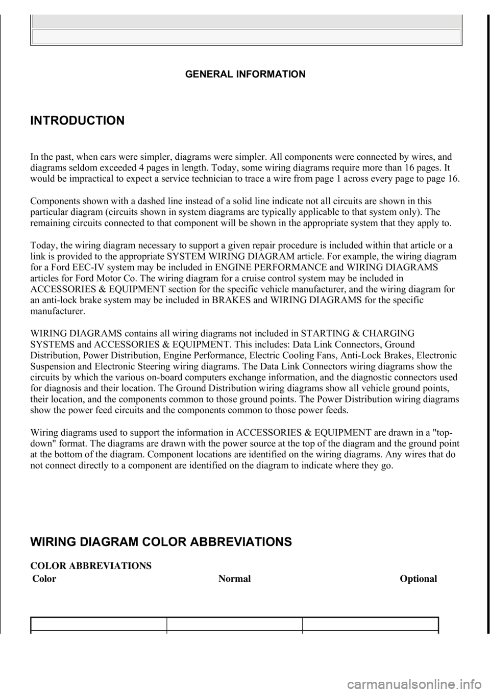
In the past, when cars were simpler, diagrams were simpler. All components were connected by wires, and
diagrams seldom exceeded 4 pages in length. Today, some wiring diagrams require more than 16 pages. It
would be impractical to expect a service technician to trace a wire from page 1 across every page to page 16.
Components shown with a dashed line instead of a solid line indicate not all circuits are shown in this
particular diagram (circuits shown in system diagrams are typically applicable to that system only). The
remaining circuits connected to that component will be shown in the appropriate system that they apply to.
Today, the wiring diagram necessary to support a given repair procedure is included within that article or a
link is provided to the appropriate SYSTEM WIRING DIAGRAM article. For example, the wiring diagram
for a Ford EEC-IV system may be included in ENGINE PERFORMANCE and WIRING DIAGRAMS
articles for Ford Motor Co. The wiring diagram for a cruise control system may be included in
ACCESSORIES & EQUIPMENT section for the specific vehicle manufacturer, and the wiring diagram for
an anti-lock brake system may be included in BRAKES and WIRING DIAGRAMS for the specific
manufacturer.
WIRING DIAGRAMS cont ains all wiring diagrams not in cluded in STARTING & CHARGING
SYSTEMS and ACCESSORIES & EQUIPMENT. Th is includes: Data Link Connectors, Ground
Distribution, Power Distribution, Engine Performance, Electri c Cooling Fans, Anti-Lock Brakes, Electronic
Suspension and Electronic Steering wiring diagrams. The Data Link Conne ctors wiring diagrams show the
circuits by which the various on-board computers exchange information, and the diagnostic connectors used
for diagnosis and their location. The Ground Distribution wi ring diagrams show all vehicle ground points,
their location, and the components co mmon to those ground points. The Po wer Distribution wiring diagrams
show the power feed circuits and the components common to those power feeds.
Wiring diagrams used to support the information in ACCESSORIES & EQUIPMEN T are drawn in a "top-
down" format. The diagrams are drawn with the power source at the top of the diagram and the ground point
at the bottom of the diagram. Component locations are identified on the wiring diagrams. Any wires that do
not connect directly to a component are identifi ed on the diagram to indicate where they go.
WIRING DIAGRAM COLOR ABBREVIATIONS
COLOR ABBREVIATIONS
ColorNormalOptional
GENERAL INFORMATI
G
111
15 ноября 2011 г. 20:18:43Page 1 © 2006 Mitchell Repair Information Company, LLC.
111
15 ноября 2011 г. 20:18:48Page 1 © 2006 Mitchell Repair Information Company, LLC.
Page 4150 of 4378

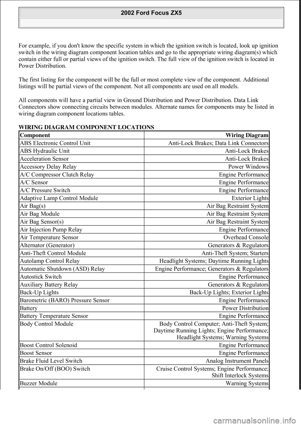
For example, if you don't know the specific system in which the ignition switch is located, look up ignition
switch in the wiring diagram component location tables and go to the appropriate wiring diagram(s) which
contain either full or partial views of the ignition swit ch. The full view of the ignition switch is located in
Power Distribution.
The first listing for the component will be the full or most complete view of the component. Additional
listings will be partial views of the component. Not all components are used on all models.
All components will have a partial view in Gr ound Distribution and Power Distribution. Data Link
Connectors show connecting circuits between modules. Alternate names for components may be listed in
wiring diagram component locations tables.
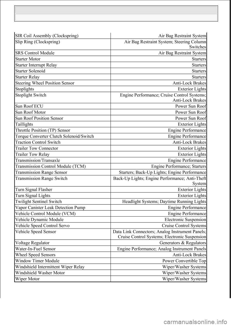
WIRING DIAGRAM COMPONENT LOCATIONS
ComponentWiring Diagram
ABS Electronic Control UnitAnti-Lock Brakes; Data Link Connectors
ABS Hydraulic UnitAnti-Lock Brakes
Acceleration SensorAnti-Lock Brakes
Accessory Delay RelayPower Windows
A/C Compressor Clutch RelayEngine Performance
A/C SensorEngine Performance
A/C Pressure SwitchEngine Performance
Adaptive Lamp Control ModuleExterior Lights
Air Bag(s)Air Bag Restraint System
Air Bag ModuleAir Bag Restraint System
Air Bag Sensor(s)Air Bag Restraint System
Air Injection Pump RelayEngine Performance
Air Temperature SensorOverhead Console
Alternator (Generator)Generators & Regulators
Anti-Theft Control ModuleAnti-Theft System; Starters
Autolamp Control RelayHeadlight Systems; Daytime Running Lights
Automatic Shutdown (ASD) RelayEngine Performance; Generators & Regulators
Autostick SwitchEngine Performance
Auxiliary Battery RelayGenerators & Regulators
Back-Up LightsBack-Up Lights; Exterior Lights
Barometric (BARO) Pressure SensorEngine Performance
BatteryPower Distribution
Battery Temperature SensorEngine Performance
Body Control ModuleBody Control Computer; Anti-Theft System;
Daytime Running Lights; Engine Performance;
Headlight Systems; Warning Systems
Boost Control SolenoidEngine Performance
Boost SensorEngine Performance
Brake Fluid Level SwitchAnalog Instrument Panels
Brake On/Off (BOO) SwitchCruise Control Systems; Engine Performance;
Shift Interlock Systems
Buzzer ModuleWarning Systems
2002 Ford Focus ZX5
111
15 ноября 2011 г. 20:18:43Page 5 © 2006 Mitchell Repair Information Company, LLC.
Page 4154 of 4378

SIR Coil Assembly (Clockspring)Air Bag Restraint System
Slip Ring (Clockspring)Air Bag Restraint System; Steering Column Switches
SRS Control ModuleAir Bag Restraint System
Starter MotorStarters
Starter Interrupt RelayStarters
Starter SolenoidStarters
Starter RelayStarters
Steering Wheel Position SensorAnti-Lock Brakes
StoplightsExterior Lights
Stoplight SwitchEngine Performance; Cruise Control Systems;
Anti-Lock Brakes
Sun Roof ECUPower Sun Roof
Sun Roof MotorPower Sun Roof
Sun Roof Position SensorPower Sun Roof
TaillightsExterior Lights
Throttle Position (TP) SensorEngine Performance
Torque Converter Clutch Solenoid/SwitchEngine Performance
Traction Control SwitchAnti-Lock Brakes
Trailer Tow ConnectorExterior Lights
Trailer Tow RelayExterior Lights
Transmission/TransaxleEngine Performance
Transmission Control Module (TCM)Engine Performance; Starters
Transmission Range SensorStarters; Back-Up Lights; Engine Performance
Transmission Range SwitchBack-Up Lights; Engine Performance; Anti-Theft
System
Turn Signal FlasherExterior Lights
Turn Signal LightsExterior Lights
Twilight Sentinel SwitchHeadlight Systems; Daytime Running Lights
Vapor Canister Le ak Detection PumpEngine Performance
Vehicle Control Module (VCM)Engine Performance
Vehicle Dynamic ModuleElectronic Suspension
Vehicle Speed Control ServoCruise Control Systems
Vehicle Speed SensorData Link Connectors; Analog Instrument Panels;
Cruise Control Systems; Electronic Suspension
Voltage RegulatorGenerators & Regulators
Water-In-Fuel SensorEngine Performance; Analog Instrument Panels
Wheel Speed SensorsAnti-Lock Brakes
Window Timer ModulePower Convertible Top
Windshield Intermittent Wiper RelayWiper/Washer Systems
Windshield Washer MotorWiper/Washer Systems
Wiper MotorWiper/Washer Systems
111
15 ноября 2011 г. 20:18:43Page 9 © 2006 Mitchell Repair Information Company, LLC.
Page 4157 of 4378
Fig. 2: 4.6L, Air Conditioning Circuit
ANTI-LOCK BRAKES
2003 Ford Mustang
2003 SYSTEM WIRING DIAGRAMS Ford - Mustang
111
18 ноября 2011 г. 12:45:09Page 3 © 2006 Mitchell Repair Information Company, LLC.
Page 4158 of 4378
Fig. 3: Anti-lock Brakes Circuit
ANTI-THEFT
2003 Ford Mustang
2003 SYSTEM WIRING DIAGRAMS Ford - Mustang
111
18 ноября 2011 г. 12:45:09Page 4 © 2006 Mitchell Repair Information Company, LLC.
Page 4213 of 4378
Fig. 2: 4.6L, Air Conditioning Circuit
ANTI-LOCK BRAKES
2003 Ford Mustang GT
2003 SYSTEM WIRING DIAGRAMS Ford - Mustang
111
18 ноября 2011 г. 12:50:34Page 3 © 2006 Mitchell Repair Information Company, LLC.
Page 4214 of 4378
Fig. 3: Anti-lock Brakes Circuit
ANTI-THEFT
2003 Ford Mustang GT
2003 SYSTEM WIRING DIAGRAMS Ford - Mustang
111
18 ноября 2011 г. 12:50:34Page 4 © 2006 Mitchell Repair Information Company, LLC.
Page 4269 of 4378
Fig. 2: 4.6L, Air Conditioning Circuit
ANTI-LOCK BRAKES
2003 Ford Mustang Cobra
2003 SYSTEM WIRING DIAGRAMS Ford - Mustang
111
18 ноября 2011 г. 12:47:06Page 3 © 2006 Mitchell Repair Information Company, LLC.