Page 4150 of 4378

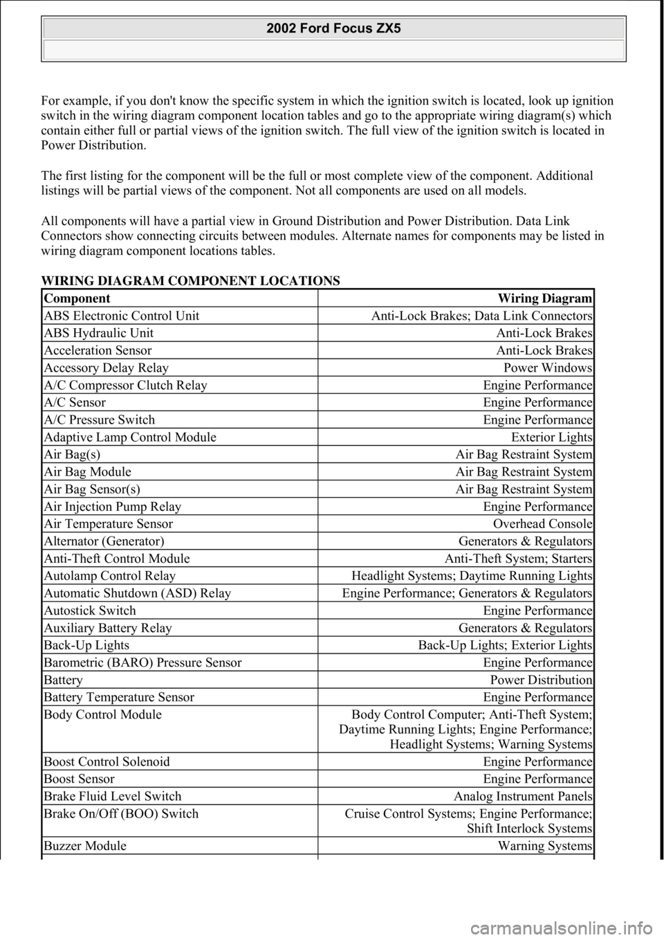
For example, if you don't know the specific system in which the ignition switch is located, look up ignition
switch in the wiring diagram component location tables and go to the appropriate wiring diagram(s) which
contain either full or partial views of the ignition swit ch. The full view of the ignition switch is located in
Power Distribution.
The first listing for the component will be the full or most complete view of the component. Additional
listings will be partial views of the component. Not all components are used on all models.
All components will have a partial view in Gr ound Distribution and Power Distribution. Data Link
Connectors show connecting circuits between modules. Alternate names for components may be listed in
wiring diagram component locations tables.
WIRING DIAGRAM COMPONENT LOCATIONS
ComponentWiring Diagram
ABS Electronic Control UnitAnti-Lock Brakes; Data Link Connectors
ABS Hydraulic UnitAnti-Lock Brakes
Acceleration SensorAnti-Lock Brakes
Accessory Delay RelayPower Windows
A/C Compressor Clutch RelayEngine Performance
A/C SensorEngine Performance
A/C Pressure SwitchEngine Performance
Adaptive Lamp Control ModuleExterior Lights
Air Bag(s)Air Bag Restraint System
Air Bag ModuleAir Bag Restraint System
Air Bag Sensor(s)Air Bag Restraint System
Air Injection Pump RelayEngine Performance
Air Temperature SensorOverhead Console
Alternator (Generator)Generators & Regulators
Anti-Theft Control ModuleAnti-Theft System; Starters
Autolamp Control RelayHeadlight Systems; Daytime Running Lights
Automatic Shutdown (ASD) RelayEngine Performance; Generators & Regulators
Autostick SwitchEngine Performance
Auxiliary Battery RelayGenerators & Regulators
Back-Up LightsBack-Up Lights; Exterior Lights
Barometric (BARO) Pressure SensorEngine Performance
BatteryPower Distribution
Battery Temperature SensorEngine Performance
Body Control ModuleBody Control Computer; Anti-Theft System;
Daytime Running Lights; Engine Performance;
Headlight Systems; Warning Systems
Boost Control SolenoidEngine Performance
Boost SensorEngine Performance
Brake Fluid Level SwitchAnalog Instrument Panels
Brake On/Off (BOO) SwitchCruise Control Systems; Engine Performance;
Shift Interlock Systems
Buzzer ModuleWarning Systems
2002 Ford Focus ZX5
111
15 ноября 2011 г. 20:18:43Page 5 © 2006 Mitchell Repair Information Company, LLC.
Page 4155 of 4378
2003 SYSTEM WIRING DIAGRAMSFord - Mustang
AIR CONDITIONING 3.8L
2003 Ford Mustang
2003 SYSTEM WIRING DIAGRAMS Ford - Mustang
2003 Ford Mustang
2003 SYSTEM WIRING DIAGRAMS Ford - Mustang
111
18 ноября 2011 г. 12:45:08Page 1 © 2006 Mitchell Repair Information Company, LLC.
111
18 ноября 2011 г. 12:45:13Page 1 © 2006 Mitchell Repair Information Company, LLC.
Page 4156 of 4378
Fig. 1: 3.8L, Air Conditioning Circuit
4.6L
2003 Ford Mustang
2003 SYSTEM WIRING DIAGRAMS Ford - Mustang
111
18 ноября 2011 г. 12:45:09Page 2 © 2006 Mitchell Repair Information Company, LLC.
Page 4157 of 4378
Fig. 2: 4.6L, Air Conditioning Circuit
ANTI-LOCK BRAKES
2003 Ford Mustang
2003 SYSTEM WIRING DIAGRAMS Ford - Mustang
111
18 ноября 2011 г. 12:45:09Page 3 © 2006 Mitchell Repair Information Company, LLC.
Page 4158 of 4378
Fig. 3: Anti-lock Brakes Circuit
ANTI-THEFT
2003 Ford Mustang
2003 SYSTEM WIRING DIAGRAMS Ford - Mustang
111
18 ноября 2011 г. 12:45:09Page 4 © 2006 Mitchell Repair Information Company, LLC.
Page 4159 of 4378
Fig. 4: Passive Anti-theft Circuit
BODY CONTROL MODULES
2003 Ford Mustang
2003 SYSTEM WIRING DIAGRAMS Ford - Mustang
111
18 ноября 2011 г. 12:45:09Page 5 © 2006 Mitchell Repair Information Company, LLC.
Page 4160 of 4378
Fig. 5: Body Control Modules Circuit
COMPUTER DATA LINES
2003 Ford Mustang
2003 SYSTEM WIRING DIAGRAMS Ford - Mustang
111
18 ноября 2011 г. 12:45:09Page 6 © 2006 Mitchell Repair Information Company, LLC.
Page 4161 of 4378
Fig. 6: Computer Data Lines Circuit
COOLING FAN
2003 Ford Mustang
2003 SYSTEM WIRING DIAGRAMS Ford - Mustang
111
18 ноября 2011 г. 12:45:09Page 7 © 2006 Mitchell Repair Information Company, LLC.