Page 3136 of 4378
DESCRIPTION AND OPERATION
Air Distribution
NOTE:
The air distribution system of this vehicle cannot be equipped with a cabin air filter.
There are two sources of air available to the air distribution system:
�zoutside air
�z recirculated air
Recirculated air is only used during MAX A/C.
Air distribution within the vehicle is determined by the function selector switch position. Airflow control
doors are used to direct airflow within the air plenum chamber. Vacuum control motors (18A318) are
used to position these airflow control doors. Refer to Section 412 - 00 for a description and operation of
each of the system functions.
The air distribution system is designed to provide airflow from the defrost nozzle when no vacuum is
applied to any of the vacuum control motors. This is done to prevent a situation where defrost cannot
be obtained due to a system vacuum leak.
Air enters the passenger compartment from the:
�zinstrument panel A/C register (19893).
�z heater outlet floor duct (18C433).
�z windshield defroster hose nozzle (18490).
�z side window demisters.
Passenger compartment air is exhausted from the vehicle through open windows or body air vents.
Instrument Panel Registers
There are A/C registers on the left and right sides of the instrument panel and in the center instrument
panel finish panel.
The LH and RH A/C registers are only serviceable as assemblies.
The center A/C registers are not serviceable as assemblies. The registers are installed with the
instrument panel center finish panel assembly. Component Locations SECTION 412-
01: Air Distribution and Filtering 2003 Mustang Workshop Manual �K�l�j . 1 �b�a
32003 Mustang Workshop Manual
18. 11. 2011file:///C:/Ford/2000 - 2004/tsocache/SHEF_2308/S3B~us~en~ ...
Page 3157 of 4378
The A/C blower motor (19805 ) pulls air from the air inlet and forces it into the plenum assembly where
it is mixed and distributed.
Heater Hoses
NOTE:
The heater water hoses connect to the heater core using quick disconnect couplers. The
couplers are an integral part of the hose assemblies and cannot be separately serviced.
The heater water hoses (18472) provide a flexible connection between the engine and cooling system
allowing hot water to travel from the engine to the heater core. �K�l�j . 2 �b�a
22003 Mustang Workshop Manual
18. 11. 2011file:///C:/Ford/2000 - 2004/tsocache/SHEF_2308/S3B~us~en~ ...
Page 3162 of 4378
REMOVAL AND INSTALLATION
Evaporator Core Housing
Removal
NOTE:
The evaporator core is not separately serviceable, it is serviced only with the evaporator core
housing assembly.
1. Disconnect the battery ground cable.
2. Recover the refrigerant. For additional information, refer to Section 412 - 00 .
3. Drain the cooling system. For additional information, refer to Section 303 - 03A or
Section 303 -
03B .
4. Remove the instrument panel. For additional information, refer to Section 501 - 12 .
5. Disconnect the heater hose couplings from the heater core. For additional information, refer to Section 412 - 00 .
6. Disconnect the vacuum connector. SECTION 412-
02: Heating and Ventilation 2003 Mustang Workshop Manual Material
Item Specification
PAG Compressor Oil (R-134a
Systems)
F7AZ- 19589- DA (Motorcraft
YN- 12-C) WSH-
M1C231-
B MERPOL®
NA ESE-
M99B144-
B �K�l�j . 1 �b�a
42003 Mustang Workshop Manual
18. 11. 2011file:///C:/Ford/2000 - 2004/tsocache/SHEF_2308/S3B~us~en~ ...
Page 3175 of 4378
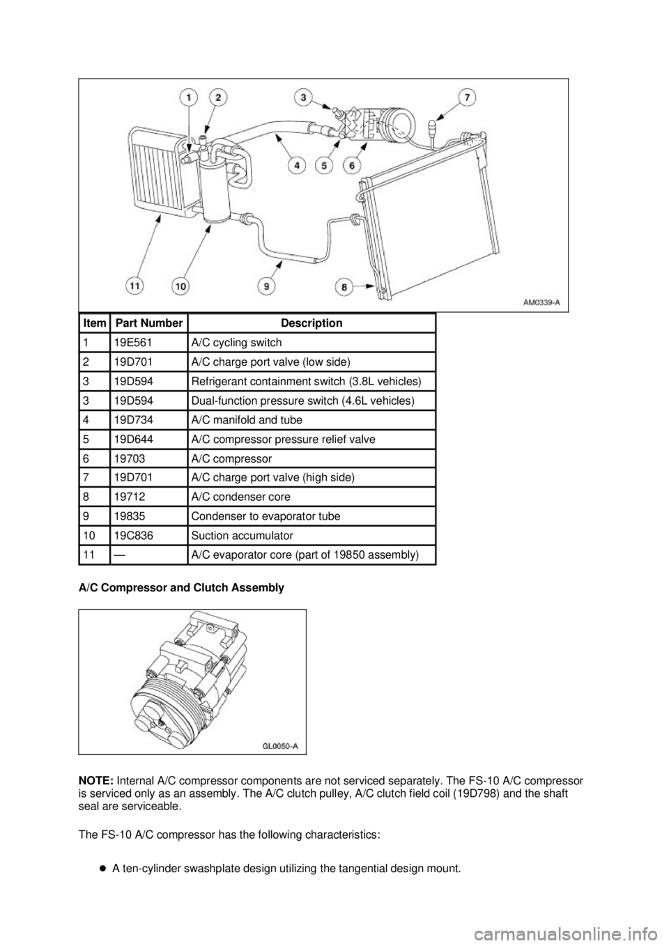
A/C Compressor and Clutch Assembly
NOTE:
Internal A/C compressor components are not serviced separately. The FS- 10 A/C compressor
is serviced only as an assembly. The A/C clutch pulley, A/C clutch field coil (19D798) and the shaft
seal are serviceable.
The FS- 10 A/C compressor has the following characteristics:
�z A ten- cylinder swashplate design utilizing the tangential design mount. Item Part Number Description
1 19E561 A/C cycling switch
2 19D701 A/C charge port valve (low side)
3 19D594 Refrigerant containment switch (3.8L vehicles)
3 19D594 Dual-
function pressure switch (4.6L vehicles) 4 19D734 A/C manifold and tube
5 19D644 A/C compressor pressure relief valve
6 19703 A/C compressor
7 19D701 A/C charge port valve (high side)
8 19712 A/C condenser core
9 19835 Condenser to evaporator tube
10 19C836 Suction accumulator
11 — A/C evaporator core (part of 19850 assembly) �K�l�j . 2 �b�a
102003 Mustang Workshop Manual
18. 11. 2011file:///C:/Ford/2000 - 2004/tsocache/SHEF_5108/S3B~us~en~ ...
Page 3177 of 4378
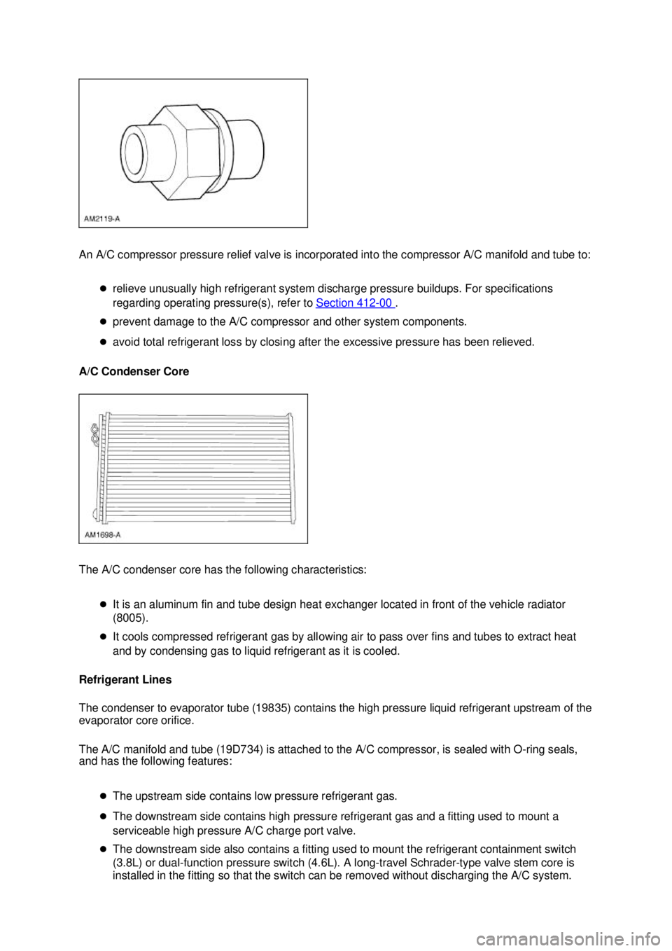
An A/C compressor pressure relief valve is incorporated into the compressor A/C manifold and tube to:
�zrelieve unusually high refrigerant system discharge pressure buildups. For specifications
regarding operating pressure(s), refer to Section 412 - 00 .
�z prevent damage to the A/C compressor and other system components.
�z avoid total refrigerant loss by closing after the excessive pressure has been relieved.
A/C Condenser Core
The A/C condenser core has the following characteristics:
�zIt is an aluminum fin and tube design heat exchanger located in front of the vehicle radiator
(8005).
�z It cools compressed refrigerant gas by allowing air to pass over fins and tubes to extract heat
and by condensing gas to liquid refrigerant as it is cooled.
Refrigerant Lines
The condenser to evaporator tube (19835) contains the high pressure liquid refrigerant upstream of the
evaporator core orifice.
The A/C manifold and tube (19D734) is attached to the A/C compressor, is sealed with O- ring seals,
and has the following features:
�zThe upstream side contains low pressure refrigerant gas.
�z The downstream side contains high pressure refrigerant gas and a fitting used to mount a
serviceable high pressure A/C charge port valve.
�z The downstream side also contains a fitting used to mount the refrigerant containment switch
(3.8L) or dual- function pressure switch (4.6L). A long- travel Schrader-type valve stem core is
installed in the fitting so that the switch can be removed without discharging the A/C system. �K�l�j . 4 �b�a
102003 Mustang Workshop Manual
18. 11. 2011file:///C:/Ford/2000 - 2004/tsocache/SHEF_5108/S3B~us~en~ ...
Page 3178 of 4378
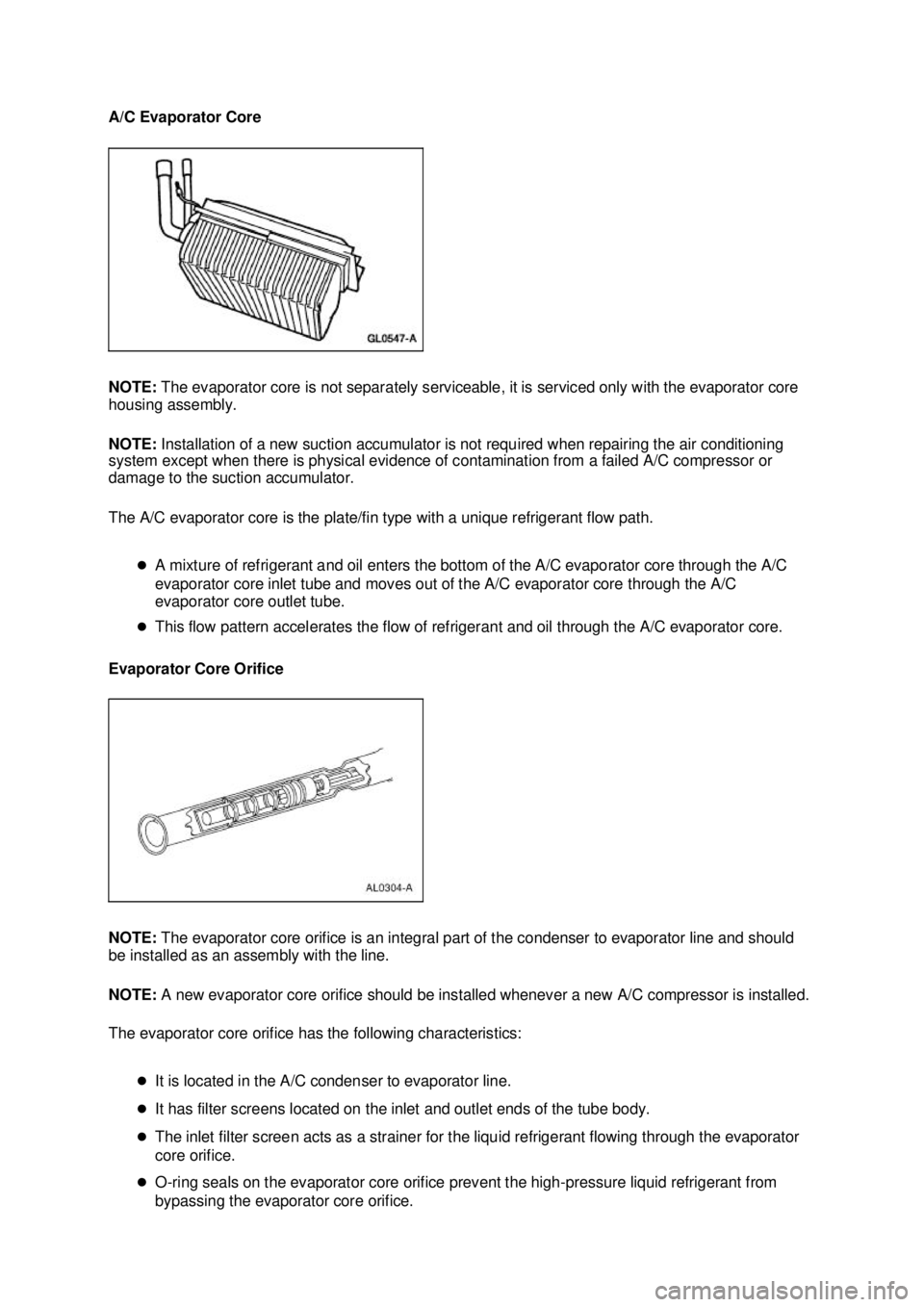
A/C Evaporator Core
NOTE:
The evaporator core is not separately serviceable, it is serviced only with the evaporator core
housing assembly.
NOTE: Installation of a new suction accumulator is not required when repairing the air conditioning
system except when there is physical evidence of contamination from a failed A/C compressor or
damage to the suction accumulator.
The A/C evaporator core is the plate/fin type with a unique refrigerant flow path.
�zA mixture of refrigerant and oil enters the bottom of the A/C evaporator core through the A/C
evaporator core inlet tube and moves out of the A/C evaporator core through the A/C
evaporator core outlet tube.
�z This flow pattern accelerates the flow of refrigerant and oil through the A/C evaporator core.
Evaporator Core Orifice
NOTE: The evaporator core orifice is an integral part of the condenser to evaporator line and should
be installed as an assembly with the line.
NOTE: A new evaporator core orifice should be installed whenever a new A/C compressor is installed.
The evaporator core orifice has the following characteristics:
�zIt is located in the A/C condenser to evaporator line.
�z It has filter screens located on the inlet and outlet ends of the tube body.
�z The inlet filter screen acts as a strainer for the liquid refrigerant flowing through the evaporator
core orifice.
�z O-ring seals on the evaporator core orifice prevent the high- pressure liquid refrigerant from
bypassing the evaporator core orifice. �K�l�j . 5 �b�a
102003 Mustang Workshop Manual
18. 11. 2011file:///C:/Ford/2000 - 2004/tsocache/SHEF_5108/S3B~us~en~ ...
Page 3179 of 4378
�z
Adjustment or repair cannot be made to the evaporator core orifice assembly. A new evaporator
core orifice must be installed as a unit.
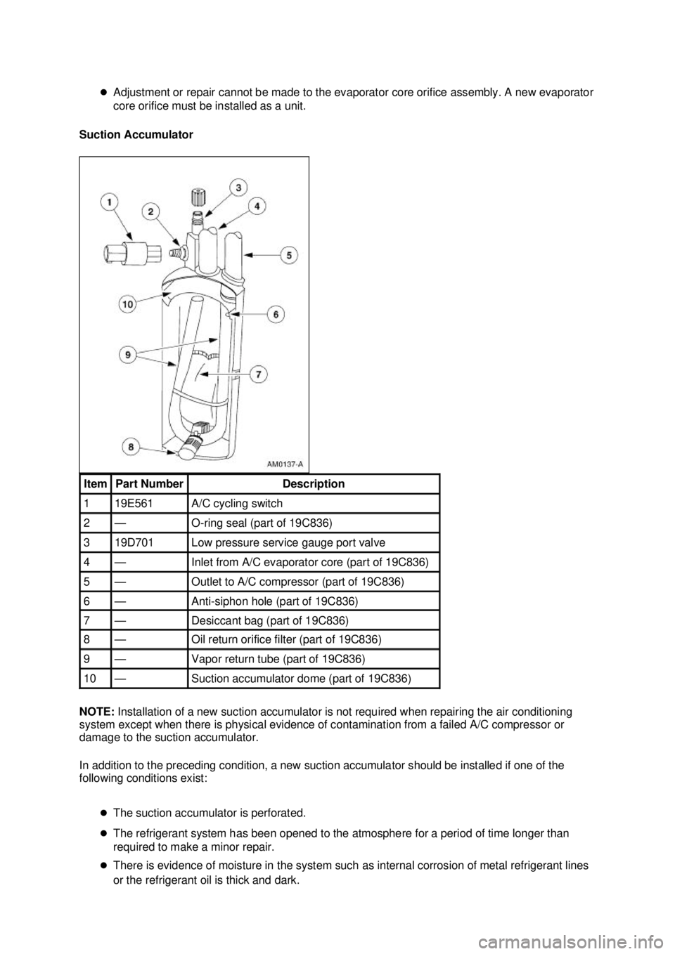
Suction Accumulator
NOTE: Installation of a new suction accumulator is not required when repairing the air conditioning
system except when there is physical evidence of contamination from a failed A/C compressor or
damage to the suction accumulator.
In addition to the preceding condition, a new suction accumulator should be installed if one of the
following conditions exist:
�zThe suction accumulator is perforated.
�z The refrigerant system has been opened to the atmosphere for a period of time longer than
required to make a minor repair.
�z There is evidence of moisture in the system such as internal corrosion of metal refrigerant lines
or the refrigerant oil is thick and dark. Item Part Number Description
1 19E561 A/C cycling switch
2 — O-
ring seal (part of 19C836) 3 19D701 Low pressure service gauge port valve
4 — Inlet from A/C evaporator core (part of 19C836)
5 — Outlet to A/C compressor (part of 19C836)
6 — Anti-
siphon hole (part of 19C836) 7 — Desiccant bag (part of 19C836)
8 — Oil return orifice filter (part of 19C836)
9 — Vapor return tube (part of 19C836)
10 — Suction accumulator dome (part of 19C836) �K�l�j . 6 �b�a
102003 Mustang Workshop Manual
18. 11. 2011file:///C:/Ford/2000 - 2004/tsocache/SHEF_5108/S3B~us~en~ ...
Page 3182 of 4378
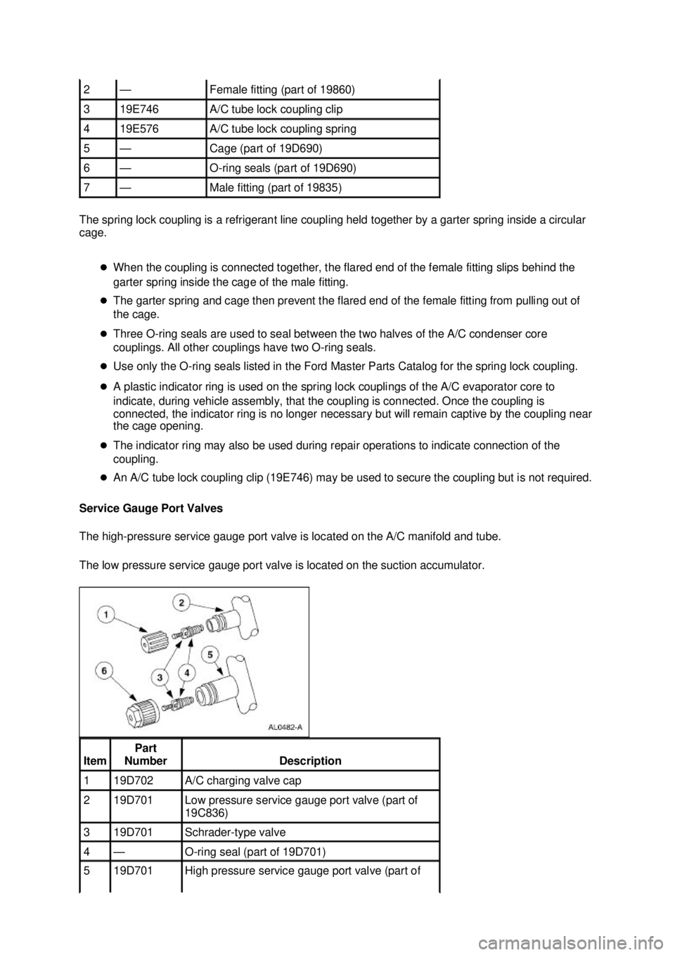
The spring lock coupling is a refrigerant line coupling held together by a garter spring inside a circular
cage.
�zWhen the coupling is connected together, the flared end of the female fitting slips behind the
garter spring inside the cage of the male fitting.
�z The garter spring and cage then prevent the flared end of the female fitting from pulling out of
the cage.
�z Three O- ring seals are used to seal between the two halves of the A/C condenser core
couplings. All other couplings have two O- ring seals.
�z Use only the O- ring seals listed in the Ford Master Parts Catalog for the spring lock coupling.
�z A plastic indicator ring is used on the spring lock couplings of the A/C evaporator core to
indicate, during vehicle assembly, that the coupling is connected. Once the coupling is
connected, the indicator ring is no longer necessary but will remain captive by the coupling near
the cage opening.
�z The indicator ring may also be used during repair operations to indicate connection of the
coupling.
�z An A/C tube lock coupling clip (19E746) may be used to secure the coupling but is not required.
Service Gauge Port Valves
The high- pressure service gauge port valve is located on the A/C manifold and tube.
The low pressure service gauge port valve is located on the suction accumulator. 2 — Female fitting (part of 19860)
3 19E746 A/C tube lock coupling clip
4 19E576 A/C tube lock coupling spring
5 — Cage (part of 19D690)
6 — O-
ring seals (part of 19D690) 7 — Male fitting (part of 19835)
Item Part
Number Description
1 19D702 A/C charging valve cap
2 19D701 Low pressure service gauge port valve (part of
19C836)
3 19D701 Schrader-
type valve 4 — O-
ring seal (part of 19D701) 5 19D701 High pressure service gauge port valve (part of �K�l�j . 9 �b�a
102003 Mustang Workshop Manual
18. 11. 2011file:///C:/Ford/2000 - 2004/tsocache/SHEF_5108/S3B~us~en~ ...