Page 2 of 256
Brakes 138
Traction control/AdvanceTrac 142
Transmission operation 144
Vehicle loading 154
Trailer towing 156
Roadside Emergencies 157
Getting roadside assistance 157
Hazard flasher switch 158
Fuel pump shut-off switch 159
Fuses and relays 160
Changing tires 165
Jump starting 170
Wrecker towing 175
Customer Assistance 176
Reporting safety defects (U.S. only) 186
Cleaning 187
Maintenance and Specifications 194
Engine compartment 197
Engine oil 199
Battery 203
Fuel information 214
Part numbers 237
Refill capacities 238
Lubricant specifications 240
Accessories 245
Index 248
All rights reserved. Reproduction by any means, electronic or
mechanical including photocopying, recording or by any
information storage and retrieval system or translation in
whole or part is not permitted without written authorization
from Ford Motor Company. Ford may change the contents
without notice and without incurring obligation.
Copyright © 2002 Ford Motor Company
Table of Contents
2
Page 4 of 256

This Owner’s Guide describes every option and
model variant available and therefore some of the
items covered may not apply to your particular
vehicle. Furthermore, due to printing cycles it may
describe options before they are generally available.
Remember to pass on the Owner’s Guide when
reselling the vehicle. It is an integral part of the
vehicle.
Fuel pump shut-off switchIn the event of
an accident the safety switch will
automatically cut off the fuel supply to the engine.
The switch can also be activated through sudden
vibration (e.g. collision when parking). To reset
the switch, refer to theFuel pump shut-off
switchin theRoadside emergencieschapter.
SAFETY AND ENVIRONMENT PROTECTION
Warning symbols in this guide
How can you reduce the risk of personal injury and
prevent possible damage to others, your vehicle and
its equipment? In this guide, answers to such
questions are contained in comments highlighted by
the warning triangle symbol. These comments
should be read and observed.
Introduction
4
Page 8 of 256
These are some of the symbols you may see on your
vehicle.
Vehicle Symbol Glossary
Safety Alert
See Owner’s Guide
Fasten Safety BeltAir Bag-Front
Air Bag-SideChild Seat
Child Seat
Installation WarningChild Seat Tether
Anchorage
Brake SystemAnti-Lock Brake
System
Brake Fluid -
Non-Petroleum
BasedTraction Control
AdvanceTracMaster Lighting
Switch
Hazard Warning
FlasherFog Lamps-Front
Fuse CompartmentFuel Pump Reset
Windshield
Wash/WipeWindshield
Defrost/Demist
Rear Window
Defrost/DemistPower Windows
Front/Rear
Power Window
LockoutChild Safety Door
Lock/Unlock
Introduction
8
Page 140 of 256

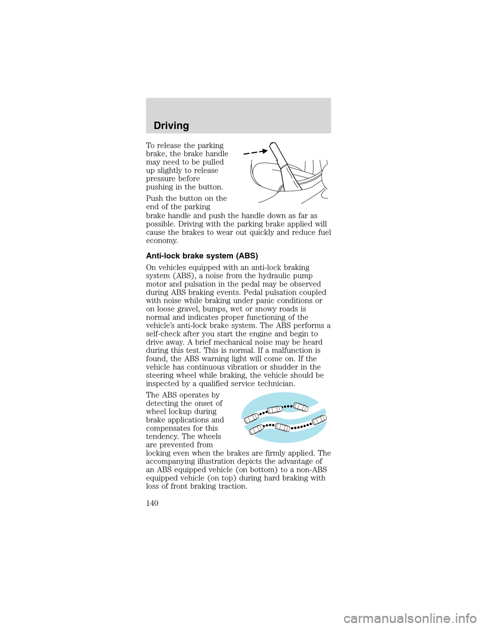
To release the parking
brake, the brake handle
may need to be pulled
up slightly to release
pressure before
pushing in the button.
Push the button on the
end of the parking
brake handle and push the handle down as far as
possible. Driving with the parking brake applied will
cause the brakes to wear out quickly and reduce fuel
economy.
Anti-lock brake system (ABS)
On vehicles equipped with an anti-lock braking
system (ABS), a noise from the hydraulic pump
motor and pulsation in the pedal may be observed
during ABS braking events. Pedal pulsation coupled
with noise while braking under panic conditions or
on loose gravel, bumps, wet or snowy roads is
normal and indicates proper functioning of the
vehicle’s anti-lock brake system. The ABS performs a
self-check after you start the engine and begin to
drive away. A brief mechanical noise may be heard
during this test. This is normal. If a malfunction is
found, the ABS warning light will come on. If the
vehicle has continuous vibration or shudder in the
steering wheel while braking, the vehicle should be
inspected by a qualified service technician.
The ABS operates by
detecting the onset of
wheel lockup during
brake applications and
compensates for this
tendency. The wheels
are prevented from
locking even when the brakes are firmly applied. The
accompanying illustration depicts the advantage of
an ABS equipped vehicle (on bottom) to a non-ABS
equipped vehicle (on top) during hard braking with
loss of front braking traction.
Driving
140
Page 159 of 256

•The hazard lights
control is located on
top of the steering
column.
•Depress hazard
lights control to
activate all hazard
flashers
simultaneously.
•Depress control again to turn the flashers off.
FUEL PUMP SHUT-OFF SWITCH
FUEL
RESET
The fuel pump shut-off switch is a device intended
to stop the electric fuel pump when your vehicle has
been involved in a substantial jolt.
After a collision, if the engine cranks but does not
start, the fuel pump shut-off switch may have been
activated.
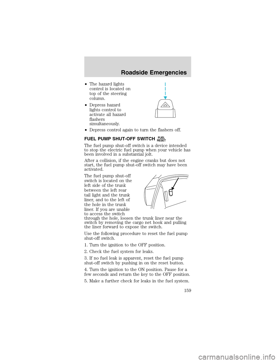
The fuel pump shut-off
switch is located on the
left side of the trunk
between the left rear
tail light and the trunk
liner, and to the left of
the hole in the trunk
liner. If you are unable
to access the switch
through the hole, loosen the trunk liner near the
switch by removing the cargo net hook and pulling
the liner forward to expose the switch.
Use the following procedure to reset the fuel pump
shut-off switch.
1. Turn the ignition to the OFF position.
2. Check the fuel system for leaks.
3. If no fuel leak is apparent, reset the fuel pump
shut-off switch by pushing in on the reset button.
4. Turn the ignition to the ON position. Pause for a
few seconds and return the key to the OFF position.
5. Make a further check for leaks in the fuel system.
Roadside Emergencies
159
Page 164 of 256
The high-current fuses are coded as follows.
Fuse/Relay
LocationFuse Amp
RatingPower Distribution Box
Description
Relay 1—Fog lamp interrupt
Relay 2—Interval wiper
Relay 3—Wiper HI/LO
Relay 4—Starter
Relay 5—Fog lamps
1 50A** (4.6L),
30A CB
(3.8L)Electric cooling fan motor
2 30A** Headlamps
3 40A** Starter motor relay, Ignition
switch
4 40A** Ignition switch
5 40A** Ignition switch
6 40A** Instrument cluster,
Powertrain Control Module
(PCM)
7 30A** Secondary air injection
(3.8L only)
8 50A** Anti-lock Brake Sytsem
(ABS) module
9 20A** Auxiliary power point
10 30A** Parklamps
11 30A** Rear window defrost control
12 40A** Power windows, Power
locks
13 30A* MACH 1000 left amplifiers
14 20A* Fuel pump
15 30A* MACH 1000 right amplifiers
16 20A* Horn
17 20A* ABS
18 30A* Power seats
19 10A* Intercooler pump (Cobra
only)
20 20A* Alternator
21—Not used
Roadside Emergencies
164
Page 215 of 256

injury. If fuel is swallowed, call a physician
immediately, even if no symptoms are immediately
apparent. The toxic effects of fuel may not be
visible for hours.
•Avoid inhaling fuel vapors. Inhaling too much fuel
vapor of any kind can lead to eye and respiratory
tract irritation. In severe cases, excessive or
prolonged breathing of fuel vapor can cause
serious illness and permanent injury.
•Avoid getting fuel liquid in your eyes. If fuel is
splashed in the eyes, remove contact lenses (if
worn), flush with water for 15 minutes and seek
medical attention. Failure to seek proper medical
attention could lead to permanent injury.
•Fuels can also be harmful if absorbed through the
skin. If fuel is splashed on the skin and/or
clothing, promptly remove contaminated clothing
and wash skin thoroughly with soap and water.
Repeated or prolonged skin contact with fuel
liquid or vapor causes skin irritation.
•Be particularly careful if you are taking
“Antabuse”or other forms of disulfiram for the
treatment of alcoholism. Breathing gasoline
vapors, or skin contact could cause an adverse
reaction. In sensitive individuals, serious personal
injury or sickness may result. If fuel is splashed
on the skin, promptly wash skin thoroughly with
soap and water. Consult a physician immediately
if you experience an adverse reaction.
When refueling always shut the engine off
and never allow sparks or open flames near
the filler neck. Never smoke while refueling. Fuel
vapor is extremely hazardous under certain
conditions. Care should be taken to avoid inhaling
excess fumes.
The flow of fuel through a fuel pump nozzle
can produce static electricity, which can
cause a fire if fuel is pumped into an ungrounded
fuel container.
Maintenance and Specifications
215
Page 216 of 256

Usethe following guidelines to avoid static build-up
when filling an ungrounded fuel container:
•Place approved fuel container on the ground.
•DO NOT fill a fuel container while it is in the
vehicle (including the cargo area).
•Keep the fuel pump nozzle in contact with the
fuel container while filling.
•DO NOT use a device that would hold the fuel
pump handle in the fill position.
Fuel Filler Cap
Your fuel tank filler cap has an indexed design with
a 1/8 turn on/off feature.
When fueling your vehicle:
1. Turn the engine off.
2. Carefully turn the filler cap counterclockwise 1/8
of a turn until it stops.
3. Pull to remove the cap from the fuel filler pipe.
4. To install the cap, align the tabs on the cap with
the notches on the filler pipe.
5. Turn the filler cap clockwise 1/8 of a turn until it
stops.
“Check Fuel Cap”illuminates when the ignition is
turned to the ON position to ensure your bulb is
working. When this light turns on, check the fuel
filler cap. Continuing to operate the vehicle with the
Check Fuel Cap light on, can activate the Service
Engine Soon warning. When the fuel filler cap is
properly re-installed, the light(s) will turn off after a
period of normal driving.It may take a long
period of time for the system to detect an
improperly installed fuel filler cap.
If you must replace the fuel filler cap, replace
it with a fuel filler cap that is designed for
your vehicle. The customer warranty may be
void for any damage to the fuel tank or fuel
system if the correct genuine Ford or
Motorcraft fuel filler cap is not used.
Maintenance and Specifications
216