Page 145 of 248

Removing key from ignition
•Turn the ignition key to position
2.
•Push the release lever forward
and rotate the key towards you
and remove.
Power-take off operation (PTO) with a manual transmission
Transmission-mounted power take-off units are available for local
installation on Ford vehicles. See your Body Builder’s Layout Book for
restrictions on use and installation of power take-off units.
To engage the PTO unit, stop the vehicle and place the transmission
control in neutral. Depress the clutch and allow the gears to stop
rotating, then engage the PTO unit. The PTO can also be selected with
the transmission in gear as long as the clutch is depressed.
When operating the PTO unit with the vehicle stationary, first set the
parking brake (chock the wheels if the vehicle is on a hill or other
unlevel surface).
BACKING UP
To avoid the possibility of personal injury while backing the
vehicle, always be sure your vehicle’s path is clear.
Before backing your vehicle, be sure you can do so safely. If anything
behind the cab limits your view, do not rely on mirrors alone to assure
that your intended path is clear. If other persons are in the vicinity, have
someone standing well behind the vehicle and outside your intended
path - visible through an exterior mirror - guide you as you back up.
Although OSHA or other governmental regulations may require use of an
electrical or mechanical back-up alarm to warn bystanders, such an
alarm does not assure that the intended path is clear.
Driving
145
Page 146 of 248

An electrical back-up alarm, if installed, is connected to the back-up
lamp circuit.
TWO-SPEED REAR AXLE
General Information
A two-speed rear axle allows the vehicle operator to selectLO rangefor
good starting and pulling power. The operator may also selectHI range
which allows for greater road speed and economy.
LO or HI range can also be used to provide additional steps between
transmission gear ratios when either gradeability or economy are a
driving factor.
Note:The two-speed rear axle should not be shifted while driving with
the speed control engaged.
Operation of the two-speed rear axle with a manual transmission
Split-shift sequence
Ratio
combination1234567891011
Transmission
gear1st 1st 2nd 2nd 3rd 3rd 4th 4th 5th 6th 6th
Axle range LO HI LO HI LO HI LO HI LO LO HI
Split-shifting upshift from LO to HI
•With the accelerator down, move the axle selector to HI by pulling the
selector up.
•Release the accelerator, then depress the clutch. Pause while the axle
upshifts, then release the clutch and depress the accelerator.
Transmission upshift and HI to LO axle
•Shift transmission to next higher gear.
•Move the axle selector to LO, by pressing the selector down, before
engaging the clutch.
Downshifting HI to LO axle
•With the accelerator down, move the axle selector to LO by pressing
the selector down.
•Rapidly release and depress the accelerator.
Driving
146
Page 147 of 248

Transmission downshift and LO to HI axle
•With the accelerator depressed, move the axle selector to HI.
•Shift transmission to next lower gear. Repeat steps in sequence as
necessary.
Operation of the two-speed rear axle with an automatic
transmission
•Use LO range for when you drive
a fully loaded vehicle on a severe
grade or in congested traffic. To
activate LO range, press the
upper portion of the control
•Use HI range for all normal
driving conditions with a lightly
loaded or partially loaded vehicle.
To activate HI range, press the
lower portion of the control.
Note:You cannot split-shifting with an automatic transmission. Also,
downshifting above64 km/h (40 mph) may result in transmission or axle
damage.
Shifting the axle from LO to HI range - vehicle stopped
Place the transmission in N (Neutral), the press the lower part of the
control.
Shifting the axle from LO to HI range - vehicle moving
Accelerate to approximately 56 km/h (35 mph), press the lower part of
the control while the transmission is in N (Neutral), then release and
apply the accelerator.
Shifting the axle from HI to LO range - vehicle stopped
Place the transmission in N (Neutral), the press the upper part of the
control.
Note:Do not shift the axle to LO range with the vehicle in motion.
LOW
2SPD
Driving
147
Page 148 of 248

Ratio extender use
Low End
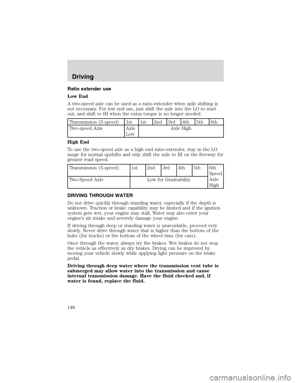
A two-speed axle can be used as a ratio-extender when split shifting is
not necessary. For low end use, just shift the axle into the LO to start
out, and shift to HI when the extra torque is no longer needed.
Transmission (5-speed) 1st 1st 2nd 3rd 4th 5th 6th
Two-speed Axle Axle
LowAxle High
High End
To use the two-speed axle as a high end ratio-extender, stay in the LO
range for normal upshifts and only shift the axle to HI on the freeway for
greater road speed.
Transmission (5-speed) 1st 2nd 3rd 4th 5th 6th
Speed
Axle
High Two-Speed Axle Low for Gradeability
DRIVING THROUGH WATER
Do not drive quickly through standing water, especially if the depth is
unknown. Traction or brake capability may be limited and if the ignition
system gets wet, your engine may stall. Water may also enter your
engine’s air intake and severely damage your engine.
If driving through deep or standing water is unavoidable, proceed very
slowly. Never drive through water that is higher than the bottom of the
hubs (for trucks) or the bottom of the wheel rims (for cars).
Once through the water, always try the brakes. Wet brakes do not stop
the vehicle as effectively as dry brakes. Drying can be improved by
moving your vehicle slowly while applying light pressure on the brake
pedal.
Driving through deep water where the transmission vent tube is
submerged may allow water into the transmission and cause
internal transmission damage. Have the fluid checked and, if
water is found, replace the fluid.
Driving
148
Page 149 of 248

MAXIMUM VEHICLE LOADING
Every vehicle manufactured by Ford
Motor Company is supplied with
information on the Vehicle Rating
Decal listing the maximum loading
for the vehicle (GVWR), and its axle
systems (GAWR) at the tire to
ground interface.
Under no circumstances should your vehicle be loaded in excess of the
GVWR or GAWR. It is the operator’s responsibility to assure that neither
the axle capacities, spring capacities, tire capacities nor the vehicle rated
GVWR is exceeded. For tire capacities, refer toMaintenance and
specificationschapter.
Unloaded or lightly loaded vehicles
The braking system has been designed to safely stop your vehicle when
fully loaded to its GVWR.
When operating empty or lightly loaded, sudden or hard braking
may induce wheel lockup with loss of vehicle control and the
possibility of accident and serious injury, especially on wet or slippery
road surfaces.
MFD. BY FORD MOTOR CO. IN U.S.A.
WB TYPE/GVW BODY TRANS AXLE EXT PNT DSO
XXX XXXXXX XXX XXX XXX XXXX XXXXXX
∇FOHT-15294A10-GA
DATE: XXXXX GVWR:XXXXX LB/ XXXXX KGFGAWR: XXXXXX/XXXXXXX RGAWR: XXXXXXX/XXXXXXX
XXXXXXXXXXXX W/TIRES XXXXXXXXXXXX W/TIRES
XXXXXXXXX RIMS XXXXXXXXX RIMS
AT XXX PSI COLD AT XXX PSI COLD
THIS VEHICLE CONFORMS TO ALL APPLICABLE FEDERAL
MOTOR VEHICLE SAFETY STANDARDS IN EFFECT ON THE
DATE OF MANUFACTURE SHOWN ABOVE.
VIN: XXXXXXXXXXXXXXXXX REAR REAR GAWR
TYPE: XXXXXXXXXXXXXXXXXX XXXXXXX/XXXXXXX
Driving
149
Page 150 of 248

GETTING ROADSIDE ASSISTANCE
To fully assist you should you have a vehicle concern, Ford offers a
complimentary roadside assistance program. This program is separate
from the New Vehicle Limited Warranty and is not applicable to vehicles
sold in Canada. The service is available:
•24–hours, seven days a week
•for the New Vehicle Limited Warranty period (U.S.) of two years
(unlimited miles)
Roadside assistance will cover:
•jump-starts.
•lock-out assistance.
•towing to the nearest Ford Motor Company dealership, or towing to
your selling dealership if within 56 km (35 miles). Even non-warranty
related tows, like accidents or getting stuck in the mud or snow, are
covered (some exclusions apply, such as impound towing or
repossession).
USING ROADSIDE ASSISTANCE
Complete the roadside assistance identification card and place it in your
wallet for quick reference. This card is found in the Owner Guide
portfolio in the glove compartment.
To receive roadside assistance in the United States, call 1-800-241-3673.
If you need to arrange roadside assistance for yourself, Ford will
reimburse a reasonable amount. To obtain information about
reimbursement, call 1-800-241-3673.
HAZARD FLASHER
Use only in an emergency to warn traffic of vehicle breakdown,
approaching danger, etc. The hazard flashers can be operated when the
ignition is off.
Roadside Emergencies
150
Page 151 of 248
•The hazard lights control is
located on top of the steering
column.
•Depress hazard lights control to
activate all hazard flashers
simultaneously.
•Depress control again to turn the
flashers off.
FUSES AND RELAYS
Fuses
If electrical components in the
vehicle are not working, a fuse may
have blown. Blown fuses are
identified by a broken wire within
the fuse. Check the appropriate
fuses before replacing any electrical
components.
Note:Always replace a fuse with one that has the specified amperage
rating. Using a fuse with a higher amperage rating can cause severe wire
damage and could start a fire.
Standard fuse amperage rating and color
COLOR
Fuse
ratingMini
fusesStandard
fusesMaxi
fusesCartridge
maxi
fusesFuse link
cartridge
2A Grey Grey———
3A Violet Violet———
4A Pink Pink———
5A Tan Tan———
7.5A Brown Brown———
10A Red Red———
15A Blue Blue———
20A Yellow Yellow Yellow Blue Blue
15
Roadside Emergencies
151
Page 152 of 248
COLOR
Fuse
ratingMini
fusesStandard
fusesMaxi
fusesCartridge
maxi
fusesFuse link
cartridge
25A Natural Natural———
30A Green Green Green Pink Pink
40A——Orange Green Green
50A——Red Red Red
60A——Blue—Yellow
70A——Ta n—Brown
80A——Natural—Black
Passenger compartment fuse panel
The fuse panel is located below and to the left of the steering wheel by
the brake pedal. Remove the panel cover to access the fuses.
To remove a fuse use the fuse puller tool provided on the fuse panel
cover.
Relay #1
Relay #2
Relay #3
Horn
Relay #4
Relay #5 One Touch
Down Interior
Lamps#1
#12#22
#2
#3
#4
#5
#6
#7
#8
#9
#10
#11#13
#23
#14
#15
#16
#17#24
#25
#26
#27
#18
#28
#19
#29
#20
#21#30
#31
Roadside Emergencies
152