Page 44 of 96
Fuse/Relay
LocationFuse Amp
RatingPower Distribution Box
Description
24 40A** IP battery feed (fuses #4, 10, 16)
25 50A** Ignition switch feed (IP fuses #1,
5, 7, 11, 13, 14, 17, 19, PDB fuses
#7, 9, 11)
26 60A** Ignition switch feed (IP fuses #5,
11, 17, 26, 32, 38)
27 30A** Multifunction switch (headlamps)
28 — Not used
29 60A** Power brake assist motor***
Relay 1 — DRL on/off relay
Relay 2 — Fuel pump relay
Relay 3 — Horn relay
Relay 4 — A/C system relay
Relay 5 — Blower motor relay
Relay 6 — PCM relay
Diode 1 — PCM diode
Diode 2 — Park brake diode
* Mini Fuses ** Maxi Fuses ***
Vehicles with Hydromax brake assist only
Relay module
The relay box is located by the power distribution box in front of the
radiator in the engine compartment.
The relays are coded as follows:
Relay location Description
1 Back up Lamp
2 Running Lamp
3 Not Used
4 Headlamp DRL
12 43
Roadside emergencies
44
Page 45 of 96
CHANGING THE TIRES
If you get a flat tire while driving, do not apply the brake heavily.
Instead, gradually decrease your speed. Hold the steering wheel firmly
and slowly move to a safe place on the side of the road.
The use of tire sealants is not recommended and may
compromise the integrity of your tires.
Tire change procedure
Preparing to change the tire
To prevent the vehicle from moving when you change a tire, be
sure the parking brake is set, then block (in both directions) the
wheel that is diagonally opposite (other side and end of the vehicle) to
the tire being changed.
1. Park on a level surface.
2. Activate the warning flashers.
3. Place the gearshift in P (Park).
4. Apply the parking brake and turn
engine OFF.
Roadside emergencies
45
Page 46 of 96

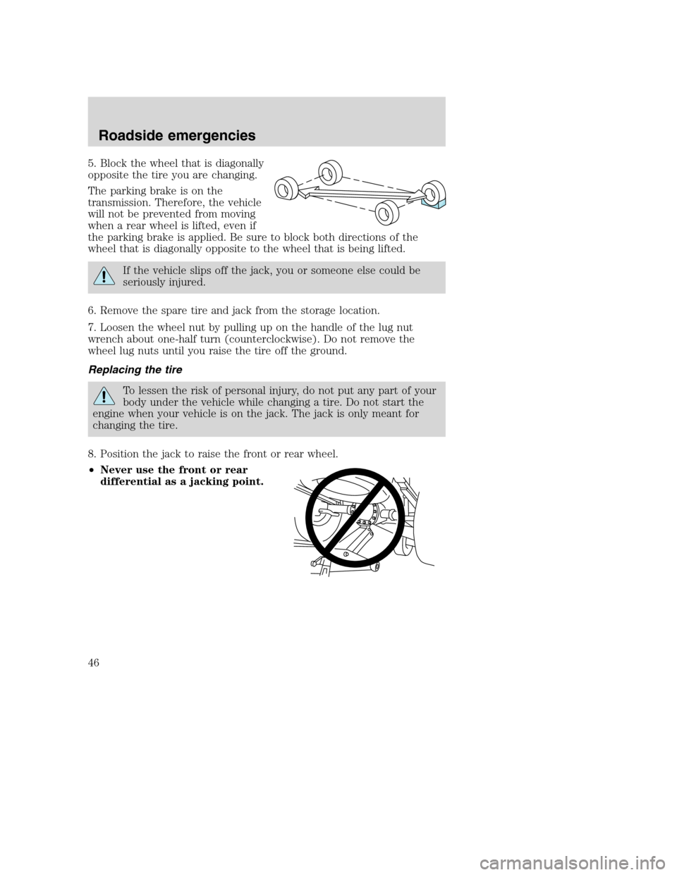
5. Block the wheel that is diagonally
opposite the tire you are changing.
The parking brake is on the
transmission. Therefore, the vehicle
will not be prevented from moving
when a rear wheel is lifted, even if
the parking brake is applied. Be sure to block both directions of the
wheel that is diagonally opposite to the wheel that is being lifted.
If the vehicle slips off the jack, you or someone else could be
seriously injured.
6. Remove the spare tire and jack from the storage location.
7. Loosen the wheel nut by pulling up on the handle of the lug nut
wrench about one-half turn (counterclockwise). Do not remove the
wheel lug nuts until you raise the tire off the ground.
Replacing the tire
To lessen the risk of personal injury, do not put any part of your
body under the vehicle while changing a tire. Do not start the
engine when your vehicle is on the jack. The jack is only meant for
changing the tire.
8. Position the jack to raise the front or rear wheel.
•Never use the front or rear
differential as a jacking point.
Roadside emergencies
46
Page 49 of 96

1.Use only a 12–volt supply to start your vehicle.
2. Do not disconnect the battery of the disabled vehicle as this could
damage the vehicle’s electrical system.
3.
Park the booster vehicle close to the hood of the disabled vehicle making
sure the two vehiclesdo nottouch. Set the parking brake on both vehicles
and stay clear of the engine cooling fan and other moving parts.
4. Check all battery terminals and remove any excessive corrosion before
you attach the battery cables. Ensure that vent caps are tight and level.
5. Turn the heater fan on in both vehicles to protect any electrical
surges. Turn all other accessories off.
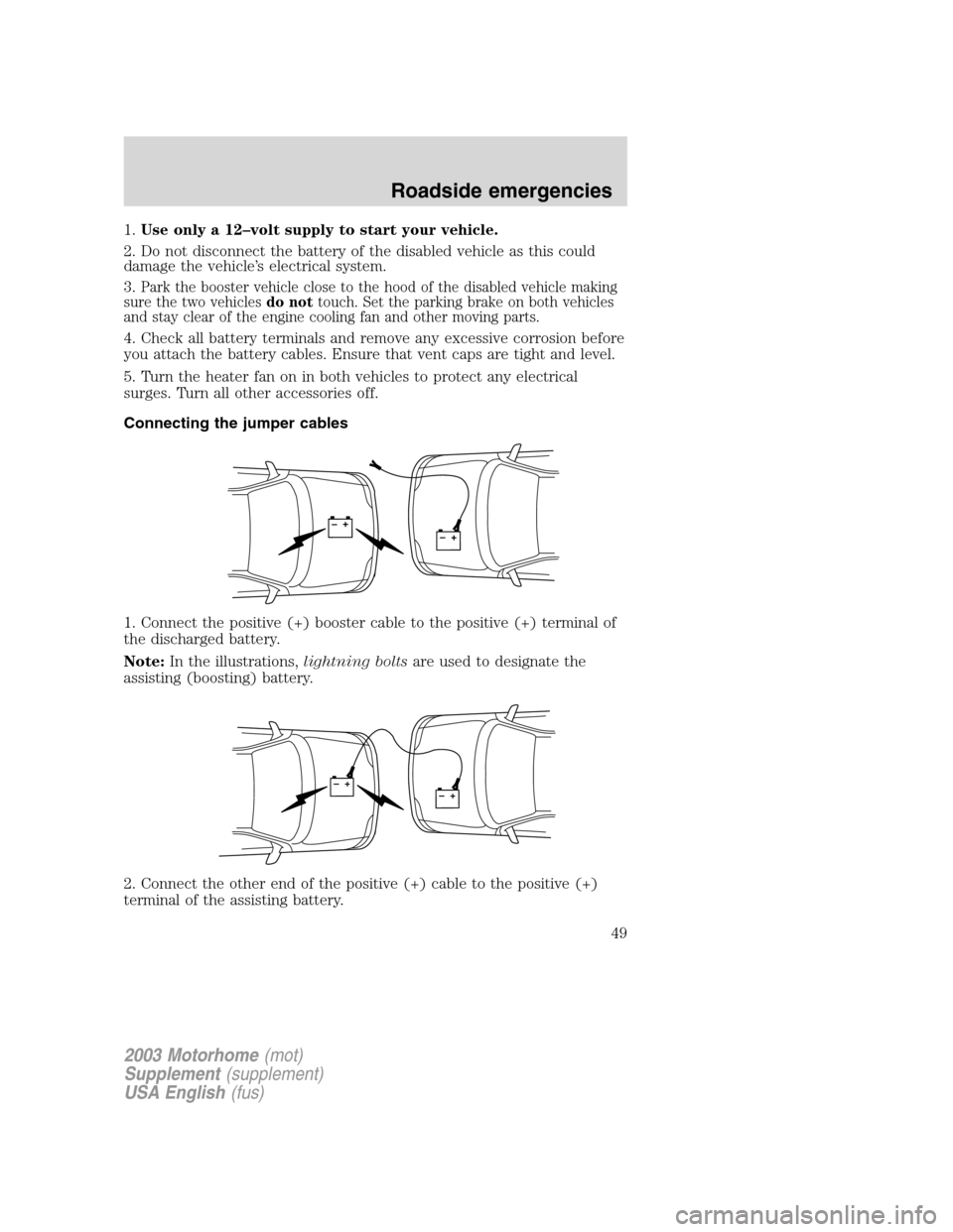
Connecting the jumper cables
1. Connect the positive (+) booster cable to the positive (+) terminal of
the discharged battery.
Note:In the illustrations,lightning boltsare used to designate the
assisting (boosting) battery.
2. Connect the other end of the positive (+) cable to the positive (+)
terminal of the assisting battery.
+–+–
+–+–
2003 Motorhome(mot)
Supplement(supplement)
USA English(fus)
Roadside emergencies
49
Page 50 of 96
3. Connect the negative (-) cable to the negative (-) terminal of the
assisting battery.
4. Make the final connection of the negative (-) cable to an exposed
metal part of the stalled vehicle’s engine, away from the battery and the
carburetor/fuel injection system.Do notuse fuel lines, engine rocker
covers or the intake manifold asgroundingpoints.
Do not connect the end of the second cable to the negative (-)
terminal of the battery to be jumped. A spark may cause an
explosion of the gases that surround the battery.
5. Ensure that the cables are clear of fan blades, belts, moving parts of
both engines, or any fuel delivery system parts.
+–+–
+–+–
2003 Motorhome(mot)
Supplement(supplement)
USA English(fus)
Roadside emergencies
50
Page 51 of 96
Jump starting
1. Start the engine of the booster vehicle and run the engine at
moderately increased speed.
2. Start the engine of the disabled vehicle.
3. Once the disabled vehicle has been started, run both engines for an
additional three minutes before disconnecting the jumper cables.
Removing the jumper cables
Remove the jumper cables in the reverse order that they were
connected.
1. Remove the jumper cable from thegroundmetal surface.
Note:In the illustrations,lightning boltsare used to designate the
assisting (boosting) battery.
2. Remove the jumper cable on the negative (-) connection of the
booster vehicle’s battery.
+–+–
+–+–
Roadside emergencies
51
Page 52 of 96
3. Remove the jumper cable from the positive (+) terminal of the booster
vehicle’s battery.
4. Remove the jumper cable from the positive (+) terminal of the
disabled vehicle’s battery.
After the disabled vehicle has been started and the jumper cables
removed, allow it to idle for several minutes so the engine computer can
relearnits idle conditions.
WRECKER TOWING
If you need to have your vehicle towed, contact a professional towing
service or, if you are a member, your roadside assistance center.
It is recommended that your vehicle be towed with a wheel lift or flatbed
equipment.
If the vehicle is towed by other means or incorrectly, vehicle
damage may occur.
When calling for a tow truck, tell the operator what kind of vehicle you
have.
+–+–
+–+–
Roadside emergencies
52
Page 54 of 96

ALUMINUM WHEELS AND WHEEL COVERS
Aluminum wheels or covers are coated with a clearcoat paint finish. In
order to maintain their shine:
•Clean weekly with Motorcraft Wheel and Tire Cleaner (ZC-37–A),
which is available from your dealer. Heavy dirt and brake dust
accumulation may require agitation with a sponge. Rinse thoroughly
with a strong stream of water.
•Never apply any cleaning chemical to hot or warm wheel rims or
covers.
•Some automatic car washes may cause damage to the finish on your
wheel rims or covers. Chemical-strength cleaners, or cleaning
chemicals, in combination with brush agitation to remove brake dust
and dirt, could wear away the clearcoat finish over time.
•Do not use hydrofluoric acid-based or high caustic-based wheel
cleaners, steel wool, fuels or strong household detergent.
•To remove tar and grease, use Ford Extra Strength Tar and Road Oil
Removal (B7A-19520–AA), available from your dealer.
ENGINE
Engines are more efficient when they are clean because grease and dirt
buildup keep the engine warmer than normal. When washing:
•Take care when using a power washer to clean the engine. The
high-pressure fluid could penetrate the sealed parts and cause
damage.
•Do not spray a hot engine with cold water to avoid cracking the
engine block or other engine components.
•Spray Motorcraft Engine Shampoo and Degreaser (ZC-20) on all parts
that require cleaning and pressure rinse clean.
•Never wash or rinse the engine while it is running; water in the
running engine may cause internal damage.
UNDERBODY
Flush the complete underside of your vehicle frequently. Keep body and
door drain holes free from packed dirt.
Cleaning
54