2003 FORD F SERIES MOTORHOME AND COMMERCIAL CHASSIS fuel pressure
[x] Cancel search: fuel pressurePage 13 of 96
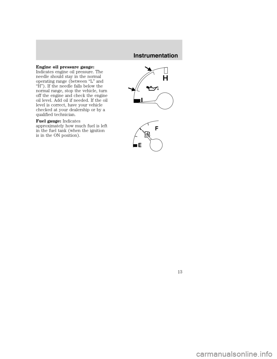
Engine oil pressure gauge:
Indicates engine oil pressure. The
needle should stay in the normal
operating range (between “L” and
“H”). If the needle falls below the
normal range, stop the vehicle, turn
off the engine and check the engine
oil level. Add oil if needed. If the oil
level is correct, have your vehicle
checked at your dealership or by a
qualified technician.
Fuel gauge:Indicates
approximately how much fuel is left
in the fuel tank (when the ignition
is in the ON position).
L
H
Instrumentation
13
Page 43 of 96
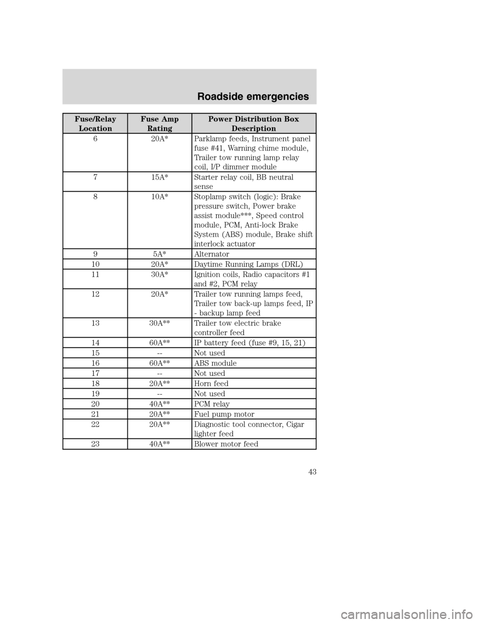
Fuse/Relay
LocationFuse Amp
RatingPower Distribution Box
Description
6 20A* Parklamp feeds, Instrument panel
fuse #41, Warning chime module,
Trailer tow running lamp relay
coil, I/P dimmer module
7 15A* Starter relay coil, BB neutral
sense
8 10A* Stoplamp switch (logic): Brake
pressure switch, Power brake
assist module***, Speed control
module, PCM, Anti-lock Brake
System (ABS) module, Brake shift
interlock actuator
9 5A* Alternator
10 20A* Daytime Running Lamps (DRL)
11 30A* Ignition coils, Radio capacitors #1
and #2, PCM relay
12 20A* Trailer tow running lamps feed,
Trailer tow back-up lamps feed, IP
- backup lamp feed
13 30A** Trailer tow electric brake
controller feed
14 60A** IP battery feed (fuse #9, 15, 21)
15 -- Not used
16 60A** ABS module
17 -- Not used
18 20A** Horn feed
19 -- Not used
20 40A** PCM relay
21 20A** Fuel pump motor
22 20A** Diagnostic tool connector, Cigar
lighter feed
23 40A** Blower motor feed
Roadside emergencies
43
Page 54 of 96
ALUMINUM WHEELS AND WHEEL COVERS
Aluminum wheels or covers are coated with a clearcoat paint finish. In
order to maintain their shine:
•Clean weekly with Motorcraft Wheel and Tire Cleaner (ZC-37–A),
which is available from your dealer. Heavy dirt and brake dust
accumulation may require agitation with a sponge. Rinse thoroughly
with a strong stream of water.
•Never apply any cleaning chemical to hot or warm wheel rims or
covers.
•Some automatic car washes may cause damage to the finish on your
wheel rims or covers. Chemical-strength cleaners, or cleaning
chemicals, in combination with brush agitation to remove brake dust
and dirt, could wear away the clearcoat finish over time.
•Do not use hydrofluoric acid-based or high caustic-based wheel
cleaners, steel wool, fuels or strong household detergent.
•To remove tar and grease, use Ford Extra Strength Tar and Road Oil
Removal (B7A-19520–AA), available from your dealer.
ENGINE
Engines are more efficient when they are clean because grease and dirt
buildup keep the engine warmer than normal. When washing:
•Take care when using a power washer to clean the engine. The
high-pressure fluid could penetrate the sealed parts and cause
damage.
•Do not spray a hot engine with cold water to avoid cracking the
engine block or other engine components.
•Spray Motorcraft Engine Shampoo and Degreaser (ZC-20) on all parts
that require cleaning and pressure rinse clean.
•Never wash or rinse the engine while it is running; water in the
running engine may cause internal damage.
UNDERBODY
Flush the complete underside of your vehicle frequently. Keep body and
door drain holes free from packed dirt.
Cleaning
54
Page 60 of 96
When lifting a plastic-cased battery, excessive pressure on the
end walls could cause acid to flow through the vent caps,
resulting in personal injury and/or damage to the vehicle or battery.
Lift the battery with a battery carrier or with your hands on opposite
corners.
Keep batteries out of reach of children. Batteries contain sulfuric
acid. Avoid contact with skin, eyes or clothing. Shield your eyes
when working near the battery to protect against possible splashing of
acid solution. In case of acid contact with skin or eyes, flush
immediately with water for a minimum of 15 minutes and get prompt
medical attention. If acid is swallowed, call a physician immediately.
Battery posts, terminals and related accessories contain lead and
lead compounds.Wash hands after handling.
To account for customer driving habits and conditions, your automatic
transmission (4R100) electronically controls the shift quality by using an
adaptive learning strategy. The adaptive learning strategy is maintained
by power from the battery. When the battery is disconnected or a new
battery is installed, the transmission must relearn its adaptive strategy.
Optimal shifting will resume within a few hundred kilometers (miles) of
operation.
If the shift quality does not improve within a few hundred
kilometers (miles) of operation, or if the downshifts and other
throttle conditions do not function normally or after a long
deceleration period, see your dealer or a qualified service
technician as soon as possible.
Because your vehicle’s engine is also electronically controlled by a
computer, some control conditions are maintained by power from the
battery. When the battery is disconnected or a new battery is installed,
the engine must relearn its idle and fuel trim strategy for optimum
driveability and performance. To begin this process:
1. With the vehicle at a complete stop, set the parking brake.
2. Put the gearshift in P (Park), turn off all accessories and start the
engine.
3. Run the engine until it reaches normal operating temperature.
4. Allow the engine to idle for at least one minute.
Maintenance and specifications
60
Page 67 of 96
Once the engine temperature cools, the engine can be re-started. Take
your vehicle to a service facility as soon as possible to minimize engine
damage.
When fail-safe mode is activated
You have limited engine power when in the fail-safe mode, so drive the
vehicle with caution. The vehicle will not be able to maintain high-speed
operation and the engine will run rough. Remember that the engine is
capable of completely shutting down automatically to prevent engine
damage, therefore:
1. Pull off the road as soon as safely possible and turn off the engine.
2. Arrange for the vehicle to be taken to a service facility.
3. If this is not possible, wait a short period for the engine to cool.
4. Check the coolant level and replenish if low.
Never remove the coolant reservoir cap while the engine is
running or hot.
5. Re-start the engine and take your vehicle to a service facility.
Driving the vehicle without repairing the engine problem
increases the chance of engine damage. Take your vehicle to a
service facility as soon as possible.
WHAT YOU SHOULD KNOW ABOUT AUTOMOTIVE FUELS
Important safety precautions
Do not overfill the fuel tank. The pressure in an overfilled tank
may cause leakage and lead to fuel spray and fire.
The fuel system may be under pressure. If the fuel filler cap is
venting vapor or if you hear a hissing sound, wait until it stops
before completely removing the fuel filler cap. Otherwise, fuel may
spray out and injure you or others.
If you do not use the proper fuel filler cap, excessive pressure or
vacuum in the fuel tank may damage the fuel system or cause
the fuel cap to disengage in a collision, which may result in possible
personal injury.
Maintenance and specifications
67
Page 71 of 96
Fuel filter replacement
The fuel filter assembly is located inside the driver side frame rail, near
the transmission.
The fuel filter should be replaced every 24 000 km (15 000 miles).
Removal
If the fuel filter is being serviced with the rear of the vehicle
higher than the front, or if the fuel tank is pressurized, fuel
leakage or siphoning from the tank fuel tubes could occur. To prevent
this condition, maintain the vehicle front end at or above the level of
the rear of the vehicle.
Do not smoke or carry lighted tobacco or open flame of any type
when working on or near any fuel related component. Highly
flammable mixtures are always present and may be ignited, resulting in
possible personal injury.
Fuel in the fuel system remains under high pressure even when
the engine is not running. Before servicing or disconnecting any
of the fuel lines or fuel system components, the fuel system pressure
must be relieved in order to prevent accidental spraying of fuel,
causing personal injury or a fire hazard.
1. Shut the engine off and relieve the fuel system pressure.
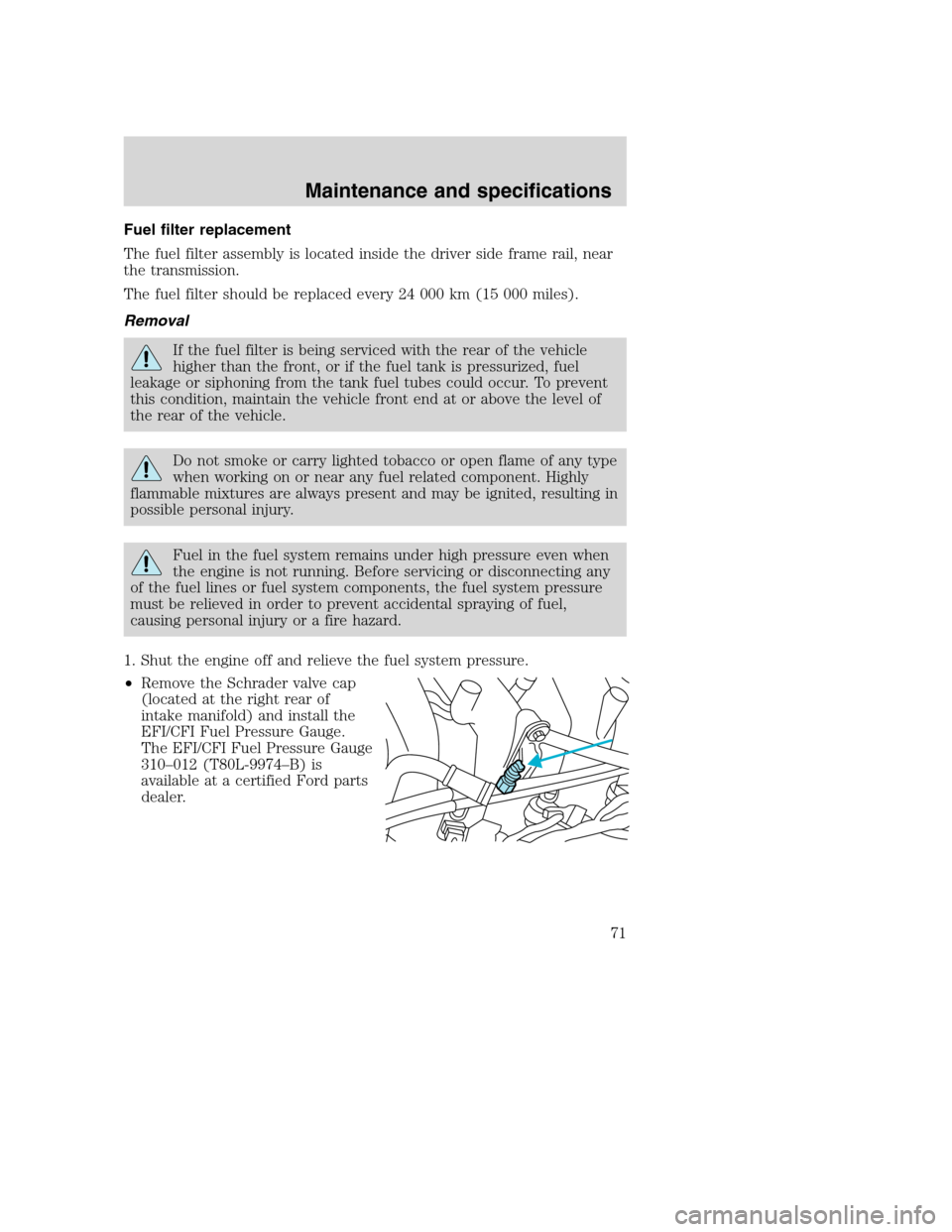
•Remove the Schrader valve cap
(located at the right rear of
intake manifold) and install the
EFI/CFI Fuel Pressure Gauge.
The EFI/CFI Fuel Pressure Gauge
310–012 (T80L-9974–B) is
available at a certified Ford parts
dealer.
Maintenance and specifications
71
Page 72 of 96
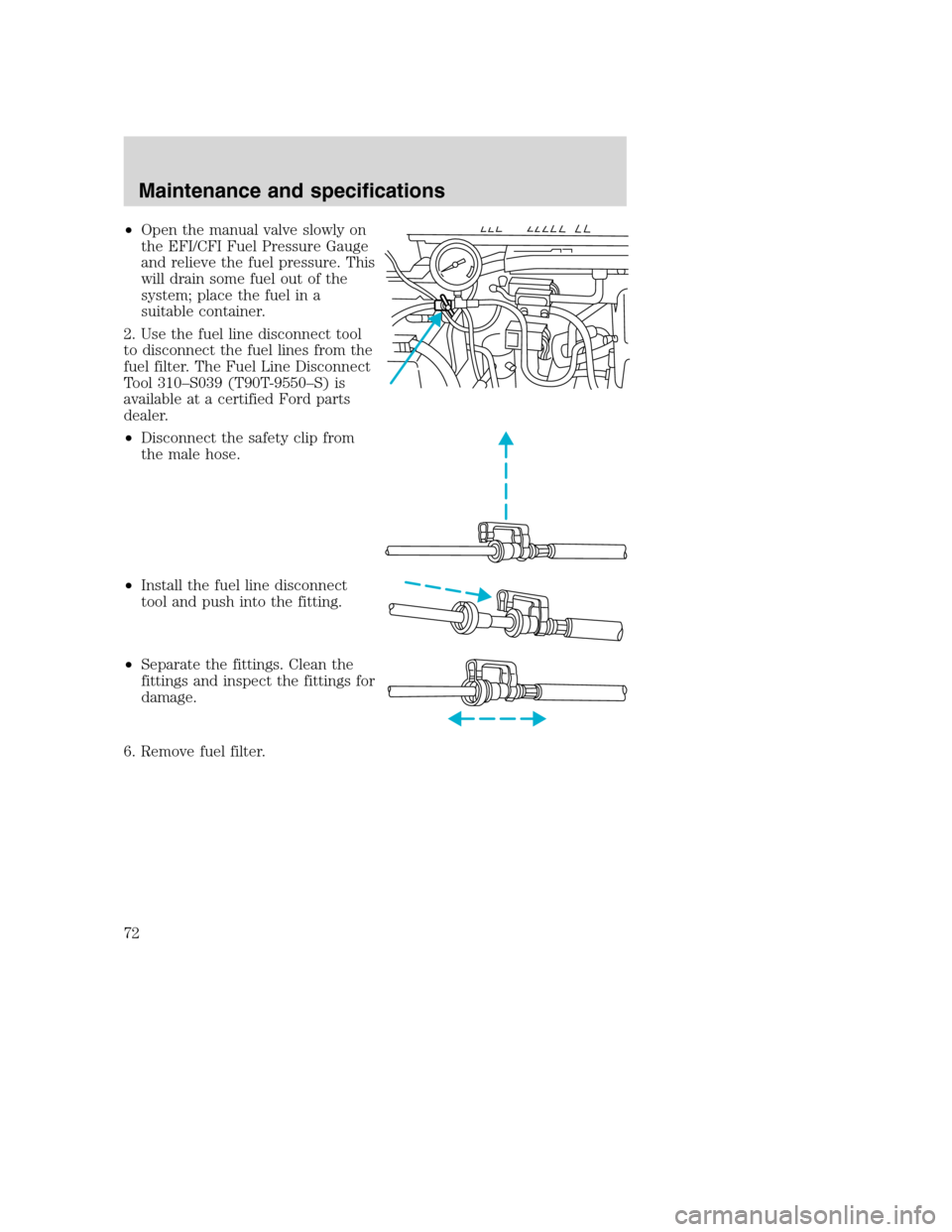
•Open the manual valve slowly on
the EFI/CFI Fuel Pressure Gauge
and relieve the fuel pressure. This
will drain some fuel out of the
system; place the fuel in a
suitable container.
2. Use the fuel line disconnect tool
to disconnect the fuel lines from the
fuel filter. The Fuel Line Disconnect
Tool 310–S039 (T90T-9550–S) is
available at a certified Ford parts
dealer.
•Disconnect the safety clip from
the male hose.
•Install the fuel line disconnect
tool and push into the fitting.
•Separate the fittings. Clean the
fittings and inspect the fittings for
damage.
6. Remove fuel filter.
Maintenance and specifications
72
Page 73 of 96
Installation
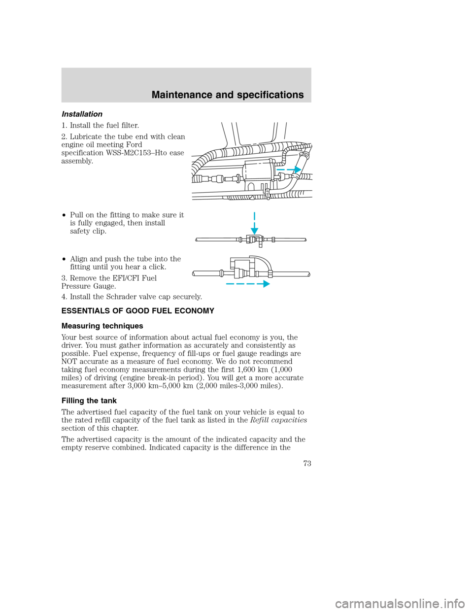
1. Install the fuel filter.
2. Lubricate the tube end with clean
engine oil meeting Ford
specification WSS-M2C153–Hto ease
assembly.
•Pull on the fitting to make sure it
is fully engaged, then install
safety clip.
•Align and push the tube into the
fitting until you hear a click.
3. Remove the EFI/CFI Fuel
Pressure Gauge.
4. Install the Schrader valve cap securely.
ESSENTIALS OF GOOD FUEL ECONOMY
Measuring techniques
Your best source of information about actual fuel economy is you, the
driver. You must gather information as accurately and consistently as
possible. Fuel expense, frequency of fill-ups or fuel gauge readings are
NOT accurate as a measure of fuel economy. We do not recommend
taking fuel economy measurements during the first 1,600 km (1,000
miles) of driving (engine break-in period). You will get a more accurate
measurement after 3,000 km–5,000 km (2,000 miles-3,000 miles).
Filling the tank
The advertised fuel capacity of the fuel tank on your vehicle is equal to
the rated refill capacity of the fuel tank as listed in theRefill capacities
section of this chapter.
The advertised capacity is the amount of the indicated capacity and the
empty reserve combined. Indicated capacity is the difference in the
Maintenance and specifications
73