Page 3 of 320
Cleaning 259
Maintenance and Specifications 265
Engine compartment 267
Engine oil 269
Battery 272
Fuel information 280
Air filter(s) 294
Low tire warning system 298
Part numbers 300
Refill capacities 300
Lubricant specifications 303
Accessories 309
Index 313
All rights reserved. Reproduction by any means, electronic or mechanical
including photocopying, recording or by any information storage and retrieval
system or translation in whole or part is not permitted without written
authorization from Ford Motor Company. Ford may change the contents without
notice and without incurring obligation.
Copyright © 2002 Ford Motor Company
Table of Contents
3
Page 9 of 320
Vehicle Symbol Glossary
Power Window Lockout
Child Safety Door
Lock/Unlock
Interior Luggage
Compartment Release
Symbol
Panic Alarm
Engine OilEngine Coolant
Engine Coolant
TemperatureDo Not Open When Hot
BatteryAvoid Smoking, Flames,
or Sparks
Battery AcidExplosive Gas
Fan WarningPower Steering Fluid
Maintain Correct Fluid
LevelMAX
MIN
Emission System
Engine Air FilterPassenger Compartment
Air Filter
JackCheck fuel cap
Low tire warning
Introduction
9
Page 12 of 320
Safety belt
Illuminates to remind you to fasten
your safety belts. For more
information, refer to theSeating
and safety restraintschapter.
Air bag readiness
Illuminates to confirm that the air
bags (front or side) are operational.
If the light fails to illuminate,
continues to flash or remains on,
have the system serviced immediately.
Charging system
Illuminates when the battery is not
charging properly.
AdvanceTrac�(if equipped)
Flashes when the AdvanceTrac�
system is active. If the light remains
on, have the system serviced
immediately.
For more information, refer to the
Drivingchapter.
Low fuel
Illuminates when the fuel level in
the fuel tank is at, or near, empty
(refer toFuel gaugein this chapter
for more information).
Low washer fluid
Illuminates when the windshield
washer fluid is low.
Instrument Cluster
12
Page 16 of 320

This gauge indicates the temperature of the engine coolant, not the
coolant level. If the coolant is not at its proper level the gauge indication
will not be accurate. If the gauge enters the red section, the oil
pressure/engine coolant andCheck Engine/Service Engine Soon
indicators illuminate, refer toWhat you should know about fail-safe
coolingin theMaintenance and specificationschapter.
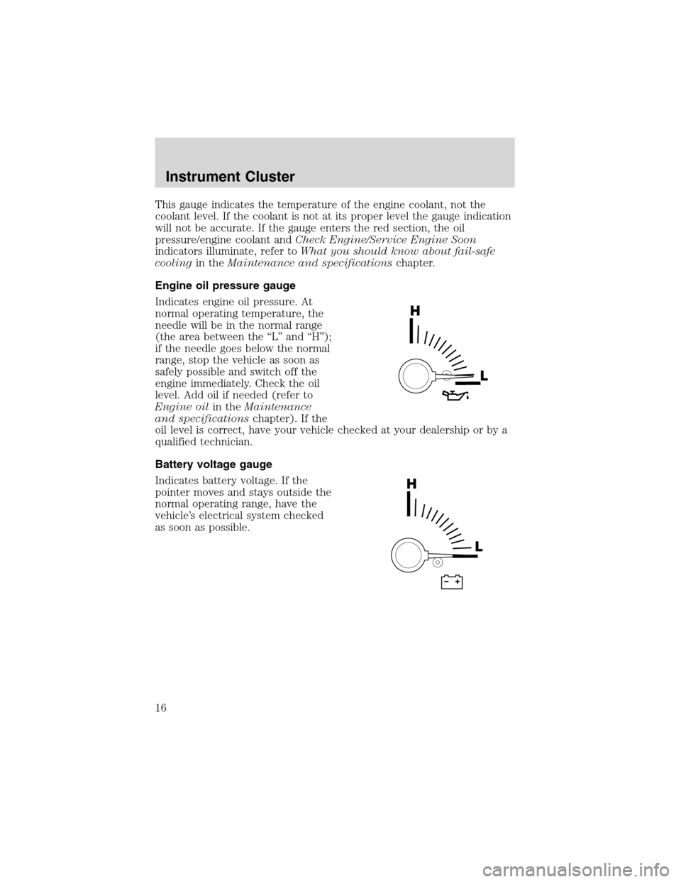
Engine oil pressure gauge
Indicates engine oil pressure. At
normal operating temperature, the
needle will be in the normal range
(the area between the“L”and“H”);
if the needle goes below the normal
range, stop the vehicle as soon as
safely possible and switch off the
engine immediately. Check the oil
level. Add oil if needed (refer to
Engine oilin theMaintenance
and specificationschapter). If the
oil level is correct, have your vehicle checked at your dealership or by a
qualified technician.
Battery voltage gauge
Indicates battery voltage. If the
pointer moves and stays outside the
normal operating range, have the
vehicle’s electrical system checked
as soon as possible.
Instrument Cluster
16
Page 62 of 320
In stop mode, press to change to rear seat mode (i.e. AM, FM, CD...)
8.VOLUMEcontrol
Press to increase (+) or decrease (-) volume level.
Battery replacement
Batteries are supplied with the
remote control unit. Since all
batteries have a limited shelf life,
replace them when the unit fails to
control the DVD player. There is a
LED indicator light on the remote
control that will illuminate when any
control is pressed.
Slide the battery cover off as shown on the remote control to access the
batteries.
The remote control unit uses two AAA batteries.
Parental control
To enable or disable your Rear Seat
Entertainment DVD System,
simultaneously press the memory
preset controls 3 and 5 on the front audio control.
For further information about the Rear Seat Controls, refer toRear Seat
Controlsin this chapter.
Entertainment Systems
62
Page 64 of 320

Rear Seat Entertainment DVD System protection circuits
High temperature sensor circuit
•Excessively high temperatures may cause damage to the DVD player.
•When the temperature of the DVD player becomes too hot, the high
temperature sensor circuit stops machine operation. DVD/CD will
illuminate in the radio display.
General operating tips
•When the engine is not running, use the system sparingly otherwise it
will run the battery down.
•When the ignition is turned to OFF, the Rear Seat Entertainment DVD
System is also turned OFF. When the ignition is turned ON, the
system will begin playback from the last selected media source when
the play control is pressed.
•To disable the DVD player, simultaneously press the 3 and 5 memory
presets on the radio face. To enable the DVD player again, press the 3
and 5 presets simultaneously.
•The DVD player is only capable of reading the bottom side of a disc.
When inserting a single sided disc, the label should be up. For a
multi-sided disc, the desired play side should be down when the disc
is inserted into the player.
•The DVD player is only capable of playback of DVDs and CDs. The
player is not compatible with CDR/RW media.
•DVDs are formatted by regions. This DVD system can only play region
1 DVDs (DVDs manufactured in U.S and Canada).
This unit is designed to play commercially pressed 12 cm (4.75
in) audio compact discs and DVDs only. Due to technical
incompatibility, certain recordable and re-recordable compact
discs may not function correctly when used in Ford DVD/CD
players. Irregular shaped discs, discs with a scratch protection
film attached, and discs with homemade paper (adhesive) labels
should not be inserted into the player. The label may peel and
cause the disc to become jammed. It is recommended that
homemade discs be identified with permanent felt tip marker
rather than adhesive labels. Ball point pens may damage discs.
Please contact your dealer for further information.
Entertainment Systems
64
Page 109 of 320

Retain the original transmitter for use in other vehicles as well as for
future programming procedures (i.e. new HomeLink�equipped vehicle
purchase). It is also suggested that upon the sale of the vehicle, the
programmed Homelink�Universal Transceiver buttons be erased for
security purposes, refer toProgrammingin this section.
Programming
Do not program the HomeLink�Universal Transceiver with the
vehicle parked in the garage.
Note:Your vehicle may require the ignition switch to be turned to the
ACC position for programming and/or operation of the HomeLink�.Itis
also recommended that a new battery be placed in the hand-held
transmitter of the device being programmed to HomeLink�for quicker
training and accurate transmission of the radio-frequency signal.
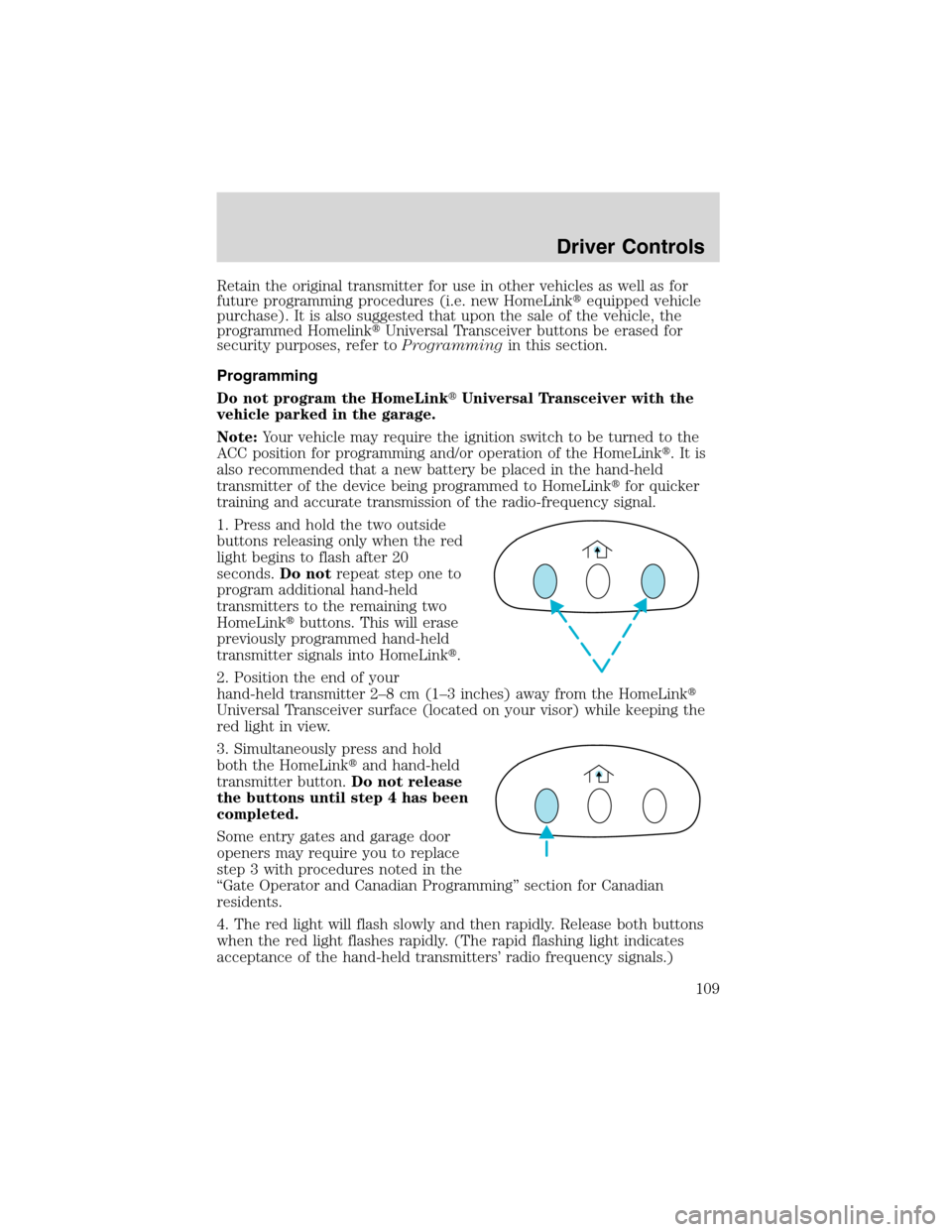
1. Press and hold the two outside
buttons releasing only when the red
light begins to flash after 20
seconds.Do notrepeat step one to
program additional hand-held
transmitters to the remaining two
HomeLink�buttons. This will erase
previously programmed hand-held
transmitter signals into HomeLink�.
2. Position the end of your
hand-held transmitter 2–8cm(1–3 inches) away from the HomeLink�
Universal Transceiver surface (located on your visor) while keeping the
red light in view.
3. Simultaneously press and hold
both the HomeLink�and hand-held
transmitter button.Do not release
the buttons until step 4 has been
completed.
Some entry gates and garage door
openers may require you to replace
step 3 with procedures noted in the
“Gate Operator and Canadian Programming”section for Canadian
residents.
4. The red light will flash slowly and then rapidly. Release both buttons
when the red light flashes rapidly. (The rapid flashing light indicates
acceptance of the hand-held transmitters’radio frequency signals.)
Driver Controls
109
Page 132 of 320

Replacing the battery
The remote transmitter is powered by one coin type three-volt lithium
battery CR2032 or equivalent. Typical operating range will allow you to
be up to 10 meters (33 feet) away from your vehicle. A decrease in
operating range can be caused by the following factors:
•Weather conditions
•Nearby radio towers
•Structures around the vehicle
•Other vehicles parked next to the vehicle
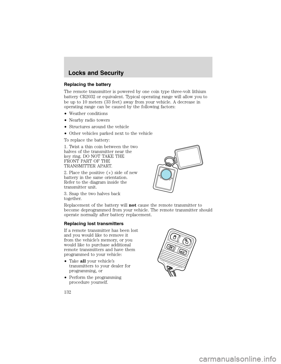
To replace the battery:
1. Twist a thin coin between the two
halves of the transmitter near the
key ring. DO NOT TAKE THE
FRONT PART OF THE
TRANSMITTER APART.
2. Place the positive (+) side of new
battery in the same orientation.
Refer to the diagram inside the
transmitter unit.
3. Snap the two halves back
together.
Replacement of the battery willnotcause the remote transmitter to
become deprogrammed from your vehicle. The remote transmitter should
operate normally after battery replacement.
Replacing lost transmitters
If a remote transmitter has been lost
and you would like to remove it
from the vehicle’s memory, or you
would like to purchase additional
remote transmitters and have them
programmed to your vehicle:
•Takeallyour vehicle’s
transmitters to your dealer for
programming, or
•Perform the programming
procedure yourself.
Locks and Security
132