2003 DODGE RAM maintenance
[x] Cancel search: maintenancePage 1694 of 2895
SPECIFICATIONS - TORQUE
TORQUE SPECIFICATIONS
DESCRIPTION N´m Ft. Lbs. In. Lbs.
Cab mount bolts 81 60 Ð
Cargo box bolts 108 80 Ð
Front crossmember bolts - 2WD 61 45 Ð
Front crossmember bolts - 4WD 102 75 Ð
Front skid plate bolts 34 25 Ð
Lower bumper support bracket bolt 54 40 Ð
Radiator crossmember bolts - lower 28 21 Ð
Radiator crossmember bolts - upper 28 21 Ð
Rear crossmember - 2WD 102 75 Ð
Rear crossmember - 4WD 102 75 Ð
Rear spring shackle bolts 163 120 Ð
Spare tire winch bolts 41 30 Ð
Trailer hitch reinforcement bracket bolt 170 125 Ð
Transfercase skid plate bolts 34 25 Ð
Transercase skid plate crossmember bolts 34 25 Ð
Transmission mount to crossmember nuts 61 45 Ð
FRONT CROSSMEMBER
REMOVAL
(1) Raise and support the vehicle. (Refer to
LUBRICATION & MAINTENANCE/HOISTING -
STANDARD PROCEDURE)
(2) Remove the front skid plate, if equipped. (Refer
to 13 - FRAME & BUMPERS/FRAME/FRONT SKID
PLATE - REMOVAL)
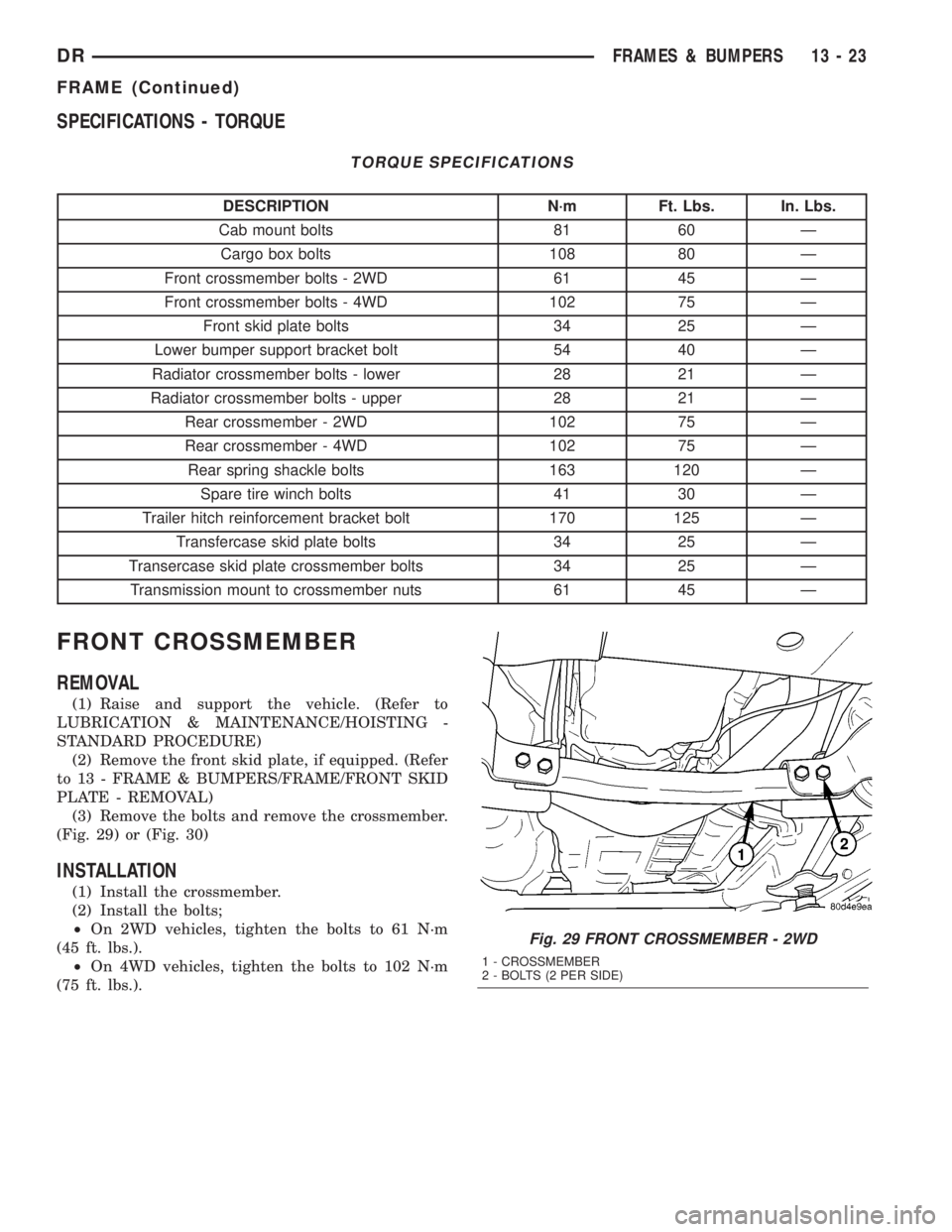
(3) Remove the bolts and remove the crossmember.
(Fig. 29) or (Fig. 30)
INSTALLATION
(1) Install the crossmember.
(2) Install the bolts;
²On 2WD vehicles, tighten the bolts to 61 N´m
(45 ft. lbs.).
²On 4WD vehicles, tighten the bolts to 102 N´m
(75 ft. lbs.).
Fig. 29 FRONT CROSSMEMBER - 2WD
1 - CROSSMEMBER
2 - BOLTS (2 PER SIDE)
DRFRAMES & BUMPERS 13 - 23
FRAME (Continued)
Page 1695 of 2895
(3) Install the front skid plate, if equipped. (Refer
to 13 - FRAME & BUMPERS/FRAME/FRONT SKID
PLATE - INSTALLATION)
FRONT SKID PLATE
REMOVAL
(1) Raise and support the vehicle. (Refer to
LUBRICATION & MAINTENANCE/HOISTING -
STANDARD PROCEDURE)
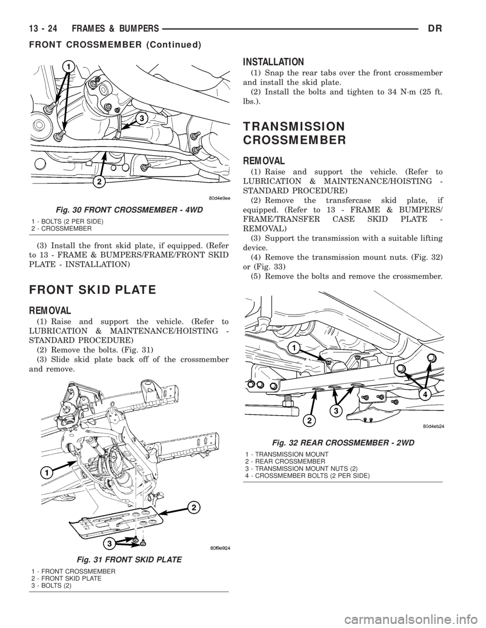
(2) Remove the bolts. (Fig. 31)
(3) Slide skid plate back off of the crossmember
and remove.
INSTALLATION
(1) Snap the rear tabs over the front crossmember
and install the skid plate.
(2) Install the bolts and tighten to 34 N´m (25 ft.
lbs.).
TRANSMISSION
CROSSMEMBER
REMOVAL
(1) Raise and support the vehicle. (Refer to
LUBRICATION & MAINTENANCE/HOISTING -
STANDARD PROCEDURE)
(2) Remove the transfercase skid plate, if
equipped. (Refer to 13 - FRAME & BUMPERS/
FRAME/TRANSFER CASE SKID PLATE -
REMOVAL)
(3) Support the transmission with a suitable lifting
device.
(4) Remove the transmission mount nuts. (Fig. 32)
or (Fig. 33)
(5) Remove the bolts and remove the crossmember.
Fig. 30 FRONT CROSSMEMBER - 4WD
1 - BOLTS (2 PER SIDE)
2 - CROSSMEMBER
Fig. 31 FRONT SKID PLATE
1 - FRONT CROSSMEMBER
2 - FRONT SKID PLATE
3 - BOLTS (2)
Fig. 32 REAR CROSSMEMBER - 2WD
1 - TRANSMISSION MOUNT
2 - REAR CROSSMEMBER
3 - TRANSMISSION MOUNT NUTS (2)
4 - CROSSMEMBER BOLTS (2 PER SIDE)
13 - 24 FRAMES & BUMPERSDR
FRONT CROSSMEMBER (Continued)
Page 1697 of 2895
TRANSFER CASE SKID PLATE
REMOVAL
(1) Raise and support the vehicle. (Refer to
LUBRICATION & MAINTENANCE/HOISTING -
STANDARD PROCEDURE)
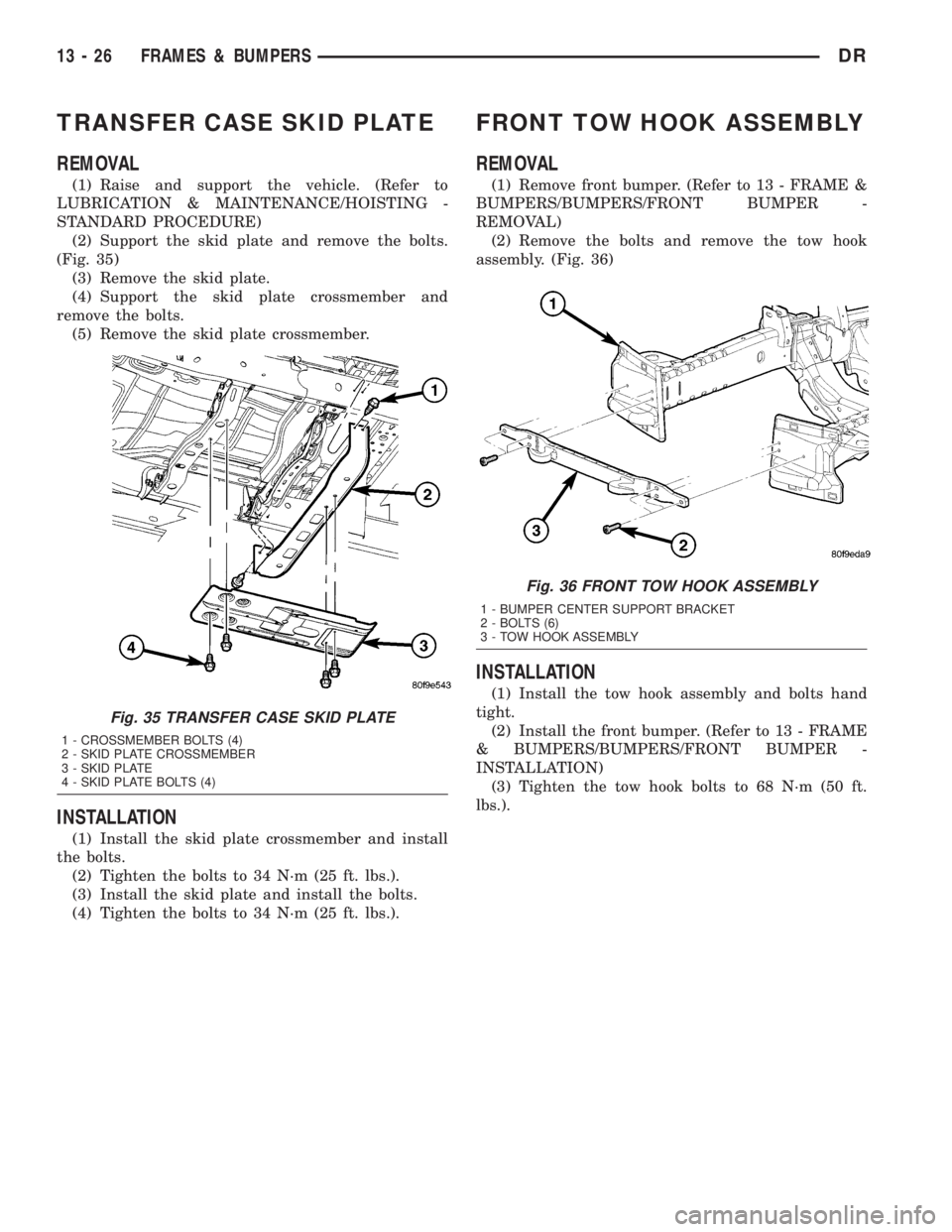
(2) Support the skid plate and remove the bolts.
(Fig. 35)
(3) Remove the skid plate.
(4) Support the skid plate crossmember and
remove the bolts.
(5) Remove the skid plate crossmember.
INSTALLATION
(1) Install the skid plate crossmember and install
the bolts.
(2) Tighten the bolts to 34 N´m (25 ft. lbs.).
(3) Install the skid plate and install the bolts.
(4) Tighten the bolts to 34 N´m (25 ft. lbs.).
FRONT TOW HOOK ASSEMBLY
REMOVAL
(1) Remove front bumper. (Refer to 13 - FRAME &
BUMPERS/BUMPERS/FRONT BUMPER -
REMOVAL)
(2) Remove the bolts and remove the tow hook
assembly. (Fig. 36)
INSTALLATION
(1) Install the tow hook assembly and bolts hand
tight.
(2) Install the front bumper. (Refer to 13 - FRAME
& BUMPERS/BUMPERS/FRONT BUMPER -
INSTALLATION)
(3) Tighten the tow hook bolts to 68 N´m (50 ft.
lbs.).
Fig. 35 TRANSFER CASE SKID PLATE
1 - CROSSMEMBER BOLTS (4)
2 - SKID PLATE CROSSMEMBER
3 - SKID PLATE
4 - SKID PLATE BOLTS (4)
Fig. 36 FRONT TOW HOOK ASSEMBLY
1 - BUMPER CENTER SUPPORT BRACKET
2 - BOLTS (6)
3 - TOW HOOK ASSEMBLY
13 - 26 FRAMES & BUMPERSDR
Page 1699 of 2895
OPERATION
Fuel is returned through the fuel pump module
and back into the fuel tank through the fuel filter/
fuel pressure regulator. A separate fuel return line
from the engine to the tank is not used.
The fuel tank assembly consists of: the fuel tank,
fuel pump module assembly, fuel pump module lock-
nut/gasket, and fuel tank check valve (refer to Fuel
Tank Check Valve for information).
A fuel filler/vent tube assembly using a pressure/
vacuum, 1/4 turn fuel filler cap is used. The fuel
filler tube contains a flap door located below the fuel
fill cap.
Also to be considered part of the fuel system is the
evaporation control system. This is designed to
reduce the emission of fuel vapors into the atmo-sphere. The description and function of the Evapora-
tive Control System is found in Emission Control
Systems.
Both fuel filters (at bottom of fuel pump module
and within fuel pressure regulator) are designed for
extended service. They do not require normal sched-
uled maintenance. Filters should only be replaced if
a diagnostic procedure indicates to do so.
STANDARD PROCEDURE - FUEL SYSTEM
PRESSURE RELEASE
Use following procedure if the fuel injector
rail is, or is not equipped with a fuel pressure
test port.
(1) Remove fuel fill cap.
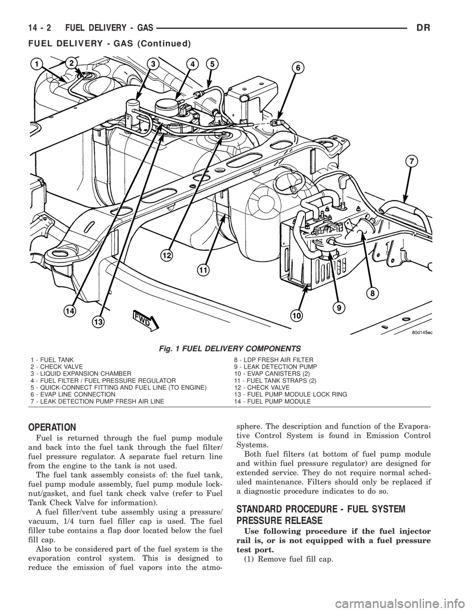
Fig. 1 FUEL DELIVERY COMPONENTS
1 - FUEL TANK 8 - LDP FRESH AIR FILTER
2 - CHECK VALVE 9 - LEAK DETECTION PUMP
3 - LIQUID EXPANSION CHAMBER 10 - EVAP CANISTERS (2)
4 - FUEL FILTER / FUEL PRESSURE REGULATOR 11 - FUEL TANK STRAPS (2)
5 - QUICK-CONNECT FITTING AND FUEL LINE (TO ENGINE) 12 - CHECK VALVE
6 - EVAP LINE CONNECTION 13 - FUEL PUMP MODULE LOCK RING
7 - LEAK DETECTION PUMP FRESH AIR LINE 14 - FUEL PUMP MODULE
14 - 2 FUEL DELIVERY - GASDR
FUEL DELIVERY - GAS (Continued)
Page 1703 of 2895
FUEL FILTER/PRESSURE
REGULATOR
DESCRIPTION
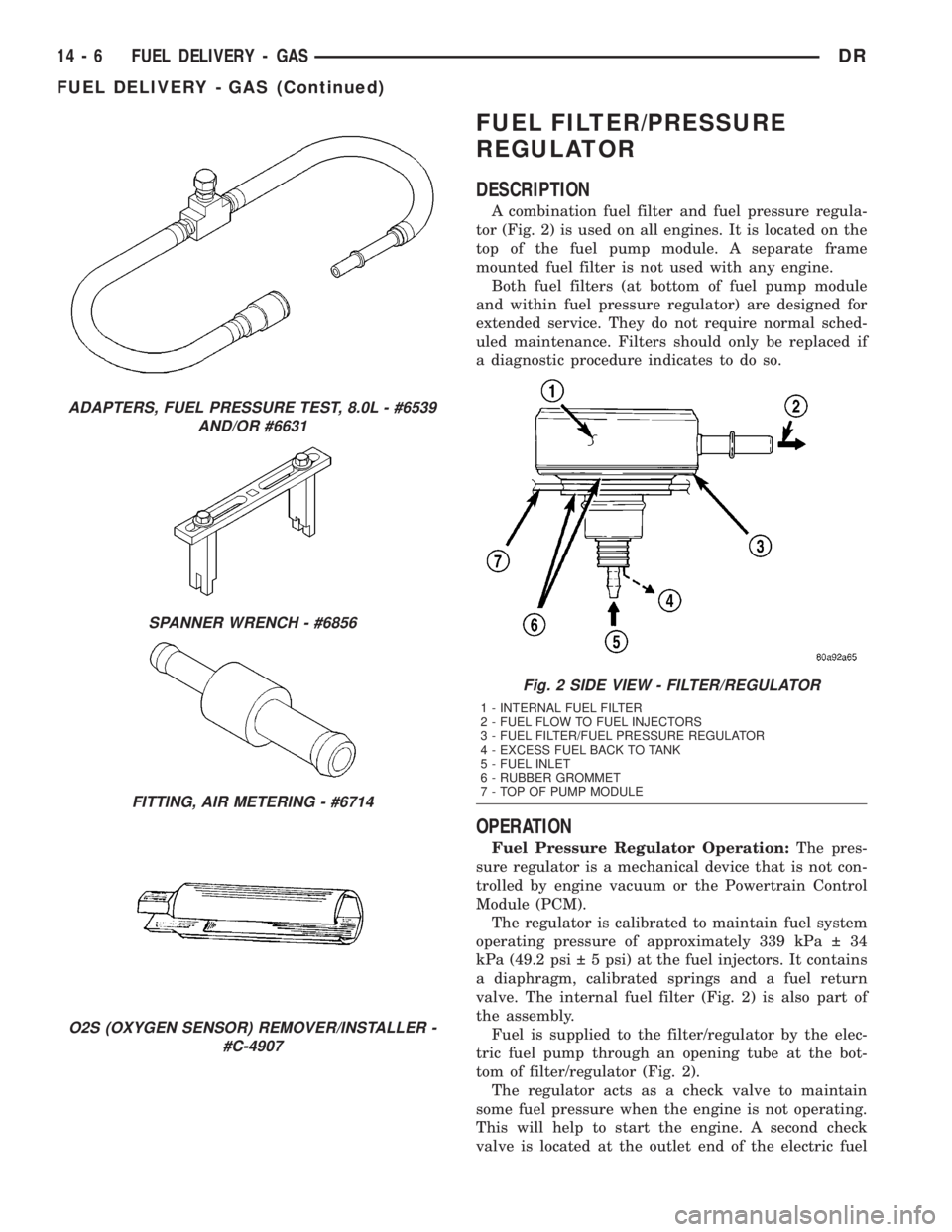
A combination fuel filter and fuel pressure regula-
tor (Fig. 2) is used on all engines. It is located on the
top of the fuel pump module. A separate frame
mounted fuel filter is not used with any engine.
Both fuel filters (at bottom of fuel pump module
and within fuel pressure regulator) are designed for
extended service. They do not require normal sched-
uled maintenance. Filters should only be replaced if
a diagnostic procedure indicates to do so.
OPERATION
Fuel Pressure Regulator Operation:The pres-
sure regulator is a mechanical device that is not con-
trolled by engine vacuum or the Powertrain Control
Module (PCM).
The regulator is calibrated to maintain fuel system
operating pressure of approximately 339 kPa 34
kPa (49.2 psi 5 psi) at the fuel injectors. It contains
a diaphragm, calibrated springs and a fuel return
valve. The internal fuel filter (Fig. 2) is also part of
the assembly.
Fuel is supplied to the filter/regulator by the elec-
tric fuel pump through an opening tube at the bot-
tom of filter/regulator (Fig. 2).
The regulator acts as a check valve to maintain
some fuel pressure when the engine is not operating.
This will help to start the engine. A second check
valve is located at the outlet end of the electric fuel
ADAPTERS, FUEL PRESSURE TEST, 8.0L - #6539
AND/OR #6631
SPANNER WRENCH - #6856
FITTING, AIR METERING - #6714
O2S (OXYGEN SENSOR) REMOVER/INSTALLER -
#C-4907
Fig. 2 SIDE VIEW - FILTER/REGULATOR
1 - INTERNAL FUEL FILTER
2 - FUEL FLOW TO FUEL INJECTORS
3 - FUEL FILTER/FUEL PRESSURE REGULATOR
4 - EXCESS FUEL BACK TO TANK
5 - FUEL INLET
6 - RUBBER GROMMET
7 - TOP OF PUMP MODULE
14 - 6 FUEL DELIVERY - GASDR
FUEL DELIVERY - GAS (Continued)
Page 1704 of 2895
pump.Refer to Fuel Pump - Description and
Operation for more information.
If fuel pressure at the pressure regulator exceeds
approximately 49.2 psi, an internal diaphragm opens
and excess fuel pressure is routed back into the tank
through the bottom of pressure regulator.
Both fuel filters (at bottom of fuel pump module
and within fuel pressure regulator) are designed for
extended service. They do not require normal sched-
uled maintenance. Filters should only be replaced if
a diagnostic procedure indicates to do so.
FUEL LEVEL SENDING UNIT /
SENSOR
DESCRIPTION
The fuel gauge sending unit (fuel level sensor) is
attached to the side of the fuel pump module. The
sending unit consists of a float, an arm, and a vari-
able resistor track (card).
OPERATION
The fuel pump module has 4 different circuits
(wires). Two of these circuits are used for the fuel
gauge sending unit for fuel gauge operation, and for
certain OBD II emission requirements. The other 2
wires are used for electric fuel pump operation.
For Fuel Gauge Operation:A constant current
source is supplied to the resistor track on the fuel
gauge sending unit. This is fed directly from the
Powertrain Control Module (PCM).NOTE: For
diagnostic purposes, this 12V power source can
only be verified with the circuit opened (fuel
pump module electrical connector unplugged).
With the connectors plugged, output voltages
will vary from about 0.6 volts at FULL, to about
8.6 volts at EMPTY (about 8.6 volts at EMPTY
for Jeep models, and about 7.0 volts at EMPTY
for Dodge Truck models).The resistor track is
used to vary the voltage (resistance) depending on
fuel tank float level. As fuel level increases, the float
and arm move up, which decreases voltage. As fuel
level decreases, the float and arm move down, which
increases voltage. The varied voltage signal is
returned back to the PCM through the sensor return
circuit.
Both of the electrical circuits between the fuel
gauge sending unit and the PCM are hard-wired (not
multi-plexed). After the voltage signal is sent from
the resistor track, and back to the PCM, the PCM
will interpret the resistance (voltage) data and send
a message across the multi-plex bus circuits to the
instrument panel cluster. Here it is translated into
the appropriate fuel gauge level reading. Refer to
Instrument Panel for additional information.For OBD II Emission Monitor Requirements:
The PCM will monitor the voltage output sent from
the resistor track on the sending unit to indicate fuel
level. The purpose of this feature is to prevent the
OBD II system from recording/setting false misfire
and fuel system monitor diagnostic trouble codes.
The feature is activated if the fuel level in the tank
is less than approximately 15 percent of its rated
capacity. If equipped with a Leak Detection Pump
(EVAP system monitor), this feature will also be acti-
vated if the fuel level in the tank is more than
approximately 85 percent of its rated capacity.
REMOVAL
The fuel level sending unit (fuel level sensor) and
float assembly is located on the side of the fuel pump
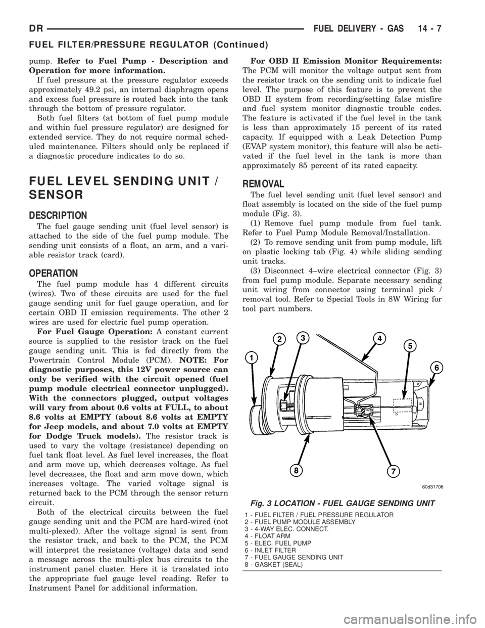
module (Fig. 3).
(1) Remove fuel pump module from fuel tank.
Refer to Fuel Pump Module Removal/Installation.
(2) To remove sending unit from pump module, lift
on plastic locking tab (Fig. 4) while sliding sending
unit tracks.
(3) Disconnect 4±wire electrical connector (Fig. 3)
from fuel pump module. Separate necessary sending
unit wiring from connector using terminal pick /
removal tool. Refer to Special Tools in 8W Wiring for
tool part numbers.
Fig. 3 LOCATION - FUEL GAUGE SENDING UNIT
1 - FUEL FILTER / FUEL PRESSURE REGULATOR
2 - FUEL PUMP MODULE ASSEMBLY
3 - 4-WAY ELEC. CONNECT.
4 - FLOAT ARM
5 - ELEC. FUEL PUMP
6 - INLET FILTER
7 - FUEL GAUGE SENDING UNIT
8 - GASKET (SEAL)
DRFUEL DELIVERY - GAS 14 - 7
FUEL FILTER/PRESSURE REGULATOR (Continued)
Page 1754 of 2895
FUEL DELIVERY - DIESEL
DESCRIPTION - DIESEL FUEL SYSTEM
The fuel system used on the Cummins engine is an
electronically controlled, Bosch HPCR (High-Pressure
Common Rail) system. The HPCR system consists of
five main components:
²Electric Fuel Transfer (lift) Pump
²Fuel Pump/Gear Pump (attached to fuel injec-
tion pump)
²High-Pressure Fuel Injection Pump
²Fuel Injection Rail
²Fuel Injectors
Also to be considered as part of the overall fuel
system are:
²Accelerator Pedal
²Air Cleaner Housing/Element
²Fuel Drain Manifold (passage)
²Fuel Drain Valve (at filter)
²Fuel Filter/Water Separator
²Fuel Heater
²Fuel Heater Relay
²Fuel Level (gauge) Sending Unit
²Fuel Tank
²Fuel Tank Module (containing fuel gauge send-
ing unit and separate fuel filter located at bottom of
tank module)
²Fuel Tank Filler/Vent Tube Assembly
²Fuel Tank Filler Tube Cap
²Fuel Tubes/Lines/Hoses
²High-Pressure Fuel Injector Lines
²In-Tank Fuel Filter (at bottom of fuel tank mod-
ule)
²Low-Pressure Fuel Supply Lines
²Low-Pressure Fuel Return Line
²Overflow Valve
²Quick-Connect Fuel Line Fittings
²Throttle Cable
²Water Draining (maintenance)
²Water-In-Fuel (WIF) Sensor
The fuel injection pump supplies high pressure to
the fuel rail independent of engine speed. This high
pressure is then accumulated in the fuel rail. High
pressure fuel is constantly supplied to the injectors
by the fuel rail. The Engine Control Module (ECM)
controls the fueling and timing of the engine by actu-
ating the injectors.Fuel enters the system from the electric fuel trans-
fer (lift) pump, which is attached to the fuel filter
assembly. Fuel is forced through the fuel filter ele-
ment and then enters the Fuel Pump/Gear Pump,
which is attached to the rear of the fuel injection
pump. The Fuel Pump/Gear Pump is a low-pressure
pump and produce pressures ranging from 551.5 kpa
(80 psi) to 1241 kpa (180) psi. Fuel then enters the
fuel injection pump. Low pressure fuel is then sup-
plied to the FCA (Fuel Control Actuator).
The FCA is an electronically controlled solenoid
valve. The ECM controls the amount of fuel that
enters the high-pressure pumping chambers by open-
ing and closing the FCA based on a demanded fuel
pressure. The FPS (Fuel Pressure Sensor) on the fuel
rail provides the actual fuel pressure. When the
actuator is opened, the maximum amount of fuel is
being supplied to the fuel injection pump. Any fuel
that does not enter the injection pump is directed to
the overflow valve. The overflow valve regulates how
much excess fuel is used for lubrication of the pump
and how much is returned to the tank through the
drain manifold.
Fuel entering the injection pump is pressurized to
between 300 - 1600 bar by three radial pumping
chambers. The pressurized fuel is then supplied to
the fuel rail.
Some fuel system components are shown in.
WARNING: HIGH-PRESSURE FUEL LINES DELIVER
DIESEL FUEL UNDER EXTREME PRESSURE FROM
THE INJECTION PUMP TO THE FUEL INJECTORS.
THIS MAY BE AS HIGH AS 160,000 KPA (23,206
PSI). USE EXTREME CAUTION WHEN INSPECTING
FOR HIGH-PRESSURE FUEL LEAKS. INSPECT FOR
HIGH-PRESSURE FUEL LEAKS WITH A SHEET OF
CARDBOARD. HIGH FUEL INJECTION PRESSURE
CAN CAUSE PERSONAL INJURY IF CONTACT IS
MADE WITH THE SKIN.
Certain fuel system components can be found in
(Fig. 1), or (Fig. 2).
STANDARD PROCEDURE
STANDARD PROCEDURES - WATER DRAINING
AT FUEL FILTER
Refer to Fuel Filter/Water Separator removal/in-
stallation for procedures.
DRFUEL DELIVERY - DIESEL 14 - 57
Page 1758 of 2895
FUEL FILTER / WATER
SEPARATOR
DESCRIPTION
The fuel filter/water separator assembly is located
on left side of engine above starter motor. The assem-
bly also includes the fuel heater and Water-In-Fuel
(WIF) sensor, and fuel transfer pump.
OPERATION
The fuel filter/water separator protects the fuel
injection pump by removing water and contaminants
from the fuel. The construction of the filter/separator
allows fuel to pass through it, but helps prevent
moisture (water) from doing so. Moisture collects at
the bottom of the canister.
Refer to the maintenance schedules for the recom-
mended fuel filter replacement intervals.
For draining of water from canister, refer to Fuel
Filter/Water Separator Removal/Installation section.A Water-In-Fuel (WIF) sensor is attached to side of
canister. Refer to Water-In-Fuel Sensor Description/
Operation.
The fuel heater is installed into the top of the fil-
ter/separator housing. Refer to Fuel Heater Descrip-
tion/Operation.
REMOVAL
Refer to maintenance schedules in this manual for
recommended fuel filter replacement intervals.
Draining water from fuel filter/water separa-
tor housing:
The housing drain valve (Fig. 3) or (Fig. 4) serves
two purposes. One is topartiallydrain filter hous-
ing of excess water. The other is tocompletelydrain
housing for fuel filter, drain valve, heater element, ,
water-in-fuel sensor replacement or transfer pump
replacement.
The filter housing should be partially drained
whenever water-in-fuel warning lamp remains illumi-
nated. (Note that lamp will be illuminated for
approximately two seconds when ignition key is ini-
tially placed in ON position for a bulb check).
(1) A drain hose (Fig. 3) or (Fig. 4) is located at
bottom of drain valve. Place drain pan under drain.
(2)With engine not running,rotate drain valve
handle rearward to OPEN (DRAIN) position. Hold
drain valve open until all water and contaminants
have been removed and clean fuel exits.
(3) If drain valve, fuel heater element or Water-In-
Fuel (WIF) sensor is being replaced, drain housing
completely. Dispose of mixture in drain pan according
to applicable regulations.
(4) After draining operation, push valve handle
forward to CLOSE position.
(5)Fuel Filter Replacement:The fuel filter is
located inside of the fuel filter housing.
(a) Clean all debris from around canister.
(b) Remove filter lid (Fig. 5) using a socket.
Attach socket to large hex on top of lid (Fig. 5).
Rotate counter-clockwise for removal. Remove
o-ring.
(c) Remove filter element by twisting element
sideways from filter lid.
(6)Water-In-Fuel (WIF) Sensor Replacement:
The WIF sensor is located on the side of the fuel fil-
ter housing (Fig. 3) or (Fig. 4).
(a) Disconnect electrical connector at sensor.
(b) Clean area around sensor.
(c) Remove sensor by rotating counter-clockwise.
(d) Check condition of sensor o-ring. Replace if
damaged.
(7)Fuel Heater Element Replacement:The
heater element is located in the fuel filter housing
(Fig. 3) or (Fig. 4).
(a) Remove fuel filter. See previous steps.
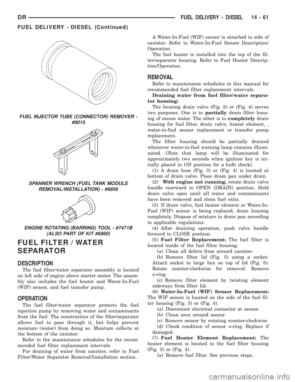
FUEL INJECTOR TUBE (CONNECTOR) REMOVER -
#9015
SPANNER WRENCH (FUEL TANK MODULE
REMOVAL/INSTALLATION) - #6856
ENGINE ROTATING (BARRING) TOOL - #7471B
(ALSO PART OF KIT #6860)
DRFUEL DELIVERY - DIESEL 14 - 61
FUEL DELIVERY - DIESEL (Continued)