2003 DODGE RAM Front differential
[x] Cancel search: Front differentialPage 2301 of 2895
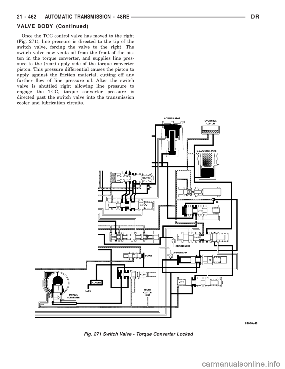
Once the TCC control valve has moved to the right
(Fig. 271), line pressure is directed to the tip of the
switch valve, forcing the valve to the right. The
switch valve now vents oil from the front of the pis-
ton in the torque converter, and supplies line pres-
sure to the (rear) apply side of the torque converter
piston. This pressure differential causes the piston to
apply against the friction material, cutting off any
further flow of line pressure oil. After the switch
valve is shuttled right allowing line pressure to
engage the TCC, torque converter pressure is
directed past the switch valve into the transmission
cooler and lubrication circuits.
Fig. 271 Switch Valve - Torque Converter Locked
21 - 462 AUTOMATIC TRANSMISSION - 48REDR
VALVE BODY (Continued)
Page 2432 of 2895
Condition Possible Cause Correction
Noisy in, or jumps out of, four wheel
drive low range.1) Transfer case not completely
engaged in 4L position.1) With the transmission in
NEUTRAL, or the clutch depressed
in the case of a manual
transmission and the vehicle moving
under 3-4 km/h (2-3 mph), shift the
transfer case to NEUTRAL and then
shift into the 4L position.
2) Shift linkage out of adjustment. 2) Adjust linkage.
3) Shift linkage loose or binding. 3) Tighten, lubricate, or repair
linkage as necessary.
4) Range fork damaged, inserts
worn, or fork is binding on the shift
rail.4) Disassemble unit and repair as
necessary.
5) Low range gear worn or
damaged.5) Disassemble unit and repair as
necessary.
Lubricant leaking from output shaft
seal or vent.1) Transfer case overfilled. 1) Drain lubricant to the correct
level.
2) Vent closed or restricted. 2) Clear or replace vent as
necessary.
3) Output shaft seals damaged or
installed incorrectly.3) Replace seal as necessary.
Check to ensure that another
component, the propeller shaft slip
yoke for example, is not causing
damage to seal.
Abnormal tire wear. 1) Extended operation on hard, dry
surfaces in the 4H position.1) Operate vehicle in the 2H
position on hard, dry surfaces.
REMOVAL
(1) Raise and support vehicle.
(2) Remove skid plate, if equipped. (Refer to 13 -
FRAMES & BUMPERS/FRAME/TRANSFER CASE
SKID PLATE - REMOVAL)
(3) Position drain oil container under transfer
case.
(4) Remove transfer case drain plug and drain
lubricant into container.
(5) Disconnect vent hose and transfer case position
sensor connector.
(6) Disconnect shift rod from grommet in transfer
case shift lever, or from floor shift arm whichever
provides easy access. Use channel lock style pliers to
press rod out of lever grommet.
(7) Support transmission with jack stand.
(8) Mark front and rear propeller shafts for assem-
bly reference.(9) Remove front and rear propeller shafts. (Refer
to 3 - DIFFERENTIAL & DRIVELINE/PROPELLER
SHAFT/PROPELLER SHAFT - REMOVAL)
(10) Support transfer case with suitable jack.
Secure transfer case to jack with safety chains.
(11) Remove nuts attaching transfer case to trans-
mission.
(12) Move transfer case assembly rearward until
free of transmission output shaft.
(13) Lower jack and move transfer case from
under vehicle.
DISASSEMBLY
Position transfer case in a shallow drain pan.
Remove drain plug and drain any remaining lubri-
cant remaining in case.
DRTRANSFER CASE - NV241 GENII 21 - 593
TRANSFER CASE - NV241 GENII (Continued)
Page 2456 of 2895
FLUID
STANDARD PROCEDURE - FLUID DRAIN AND
REFILL
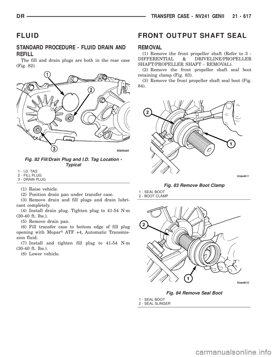
The fill and drain plugs are both in the rear case
(Fig. 82).
(1) Raise vehicle.
(2) Position drain pan under transfer case.
(3) Remove drain and fill plugs and drain lubri-
cant completely.
(4) Install drain plug. Tighten plug to 41-54 N´m
(30-40 ft. lbs.).
(5) Remove drain pan.
(6) Fill transfer case to bottom edge of fill plug
opening with MopartATF +4, Automatic Transmis-
sion fluid.
(7) Install and tighten fill plug to 41-54 N´m
(30-40 ft. lbs.).
(8) Lower vehicle.
FRONT OUTPUT SHAFT SEAL
REMOVAL
(1) Remove the front propeller shaft (Refer to 3 -
DIFFERENTIAL & DRIVELINE/PROPELLER
SHAFT/PROPELLER SHAFT - REMOVAL).
(2) Remove the front propeller shaft seal boot
retaining clamp (Fig. 83).
(3) Remove the front propeller shaft seal boot (Fig.
84).
Fig. 83 Remove Boot Clamp
1 - SEAL BOOT
2 - BOOT CLAMP
Fig. 84 Remove Seal Boot
1 - SEAL BOOT
2 - SEAL SLINGER
Fig. 82 Fill/Drain Plug and I.D. Tag Location -
Typical
1 - I.D. TAG
2 - FILL PLUG
3 - DRAIN PLUG
DRTRANSFER CASE - NV241 GENII 21 - 617
Page 2464 of 2895
Condition Possible Cause Correction
Noisy in, or jumps out of, four wheel
drive low range.1) Transfer case not completely
engaged in 4L position.1) With the transmission in
NEUTRAL, or the clutch depressed
in the case of a manual
transmission and the vehicle moving
under 3-4 km/h (2-3 mph), shift the
transfer case to NEUTRAL and then
shift into the 4L position.
2) Shift linkage out of adjustment. 2) Adjust linkage.
3) Shift linkage loose or binding. 3) Tighten, lubricate, or repair
linkage as necessary.
4) Range fork damaged, inserts
worn, or fork is binding on the shift
rail.4) Disassemble unit and repair as
necessary.
5) Low range gear worn or
damaged.5) Disassemble unit and repair as
necessary.
Lubricant leaking from output shaft
seal or vent.1) Transfer case overfilled. 1) Drain lubricant to the correct
level.
2) Vent closed or restricted. 2) Clear or replace vent as
necessary.
3) Output shaft seals damaged or
installed incorrectly.3) Replace seal as necessary.
Check to ensure that another
component, the propeller shaft slip
yoke for example, is not causing
damage to seal.
Abnormal tire wear. 1) Extended operation on hard, dry
surfaces in the 4H position.1) Operate vehicle in the 2H
position on hard, dry surfaces.
REMOVAL
(1) Raise and support vehicle.
(2) Remove skid plate, if equipped. (Refer to 13 -
FRAMES & BUMPERS/FRAME/TRANSFER CASE
SKID PLATE - REMOVAL)
(3) Position drain oil container under transfer
case.
(4) Remove transfer case drain plug and drain
lubricant into container.
(5) Disconnect vent hose and transfer case position
sensor connector.
(6) Disconnect shift rod from grommet in transfer
case shift lever, or from floor shift arm whichever
provides easy access. Use channel lock style pliers to
press rod out of lever grommet.
(7) Support transmission with jack stand.
(8) Mark front and rear propeller shafts for assem-
bly reference.
(9) Remove front and rear propeller shafts. (Refer
to 3 - DIFFERENTIAL & DRIVELINE/PROPELLER
SHAFT/PROPELLER SHAFT - REMOVAL)(10) Support transfer case with suitable jack.
Secure transfer case to jack with safety chains.
(11) Remove nuts attaching transfer case to trans-
mission.
(12) Move transfer case assembly rearward until
free of transmission output shaft.
(13) Lower jack and move transfer case from
under vehicle.
DISASSEMBLY
Position transfer case in a shallow drain pan.
Remove drain plug and drain any remaining lubri-
cant remaining in case.
COMPANION FLANGE AND EXTENSION HOUSING
(1) Install two bolts 180É apart into the front out-
put shaft companion flange.
(2) Place holder over the bolts and against the
companion flange (Fig. 3).
(3) Remove and discard the front companion flange
nut.
DRTRANSFER CASE - NV271 21 - 625
TRANSFER CASE - NV271 (Continued)
Page 2488 of 2895
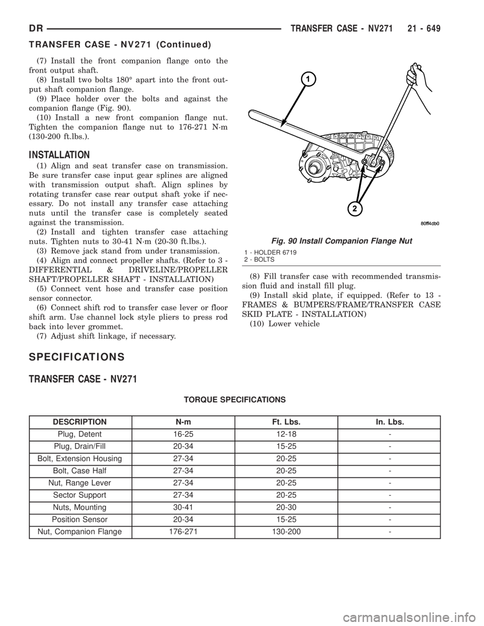
(7) Install the front companion flange onto the
front output shaft.
(8) Install two bolts 180É apart into the front out-
put shaft companion flange.
(9) Place holder over the bolts and against the
companion flange (Fig. 90).
(10) Install a new front companion flange nut.
Tighten the companion flange nut to 176-271 N´m
(130-200 ft.lbs.).
INSTALLATION
(1) Align and seat transfer case on transmission.
Be sure transfer case input gear splines are aligned
with transmission output shaft. Align splines by
rotating transfer case rear output shaft yoke if nec-
essary. Do not install any transfer case attaching
nuts until the transfer case is completely seated
against the transmission.
(2) Install and tighten transfer case attaching
nuts. Tighten nuts to 30-41 N´m (20-30 ft.lbs.).
(3) Remove jack stand from under transmission.
(4) Align and connect propeller shafts. (Refer to 3 -
DIFFERENTIAL & DRIVELINE/PROPELLER
SHAFT/PROPELLER SHAFT - INSTALLATION)
(5) Connect vent hose and transfer case position
sensor connector.
(6) Connect shift rod to transfer case lever or floor
shift arm. Use channel lock style pliers to press rod
back into lever grommet.
(7) Adjust shift linkage, if necessary.(8) Fill transfer case with recommended transmis-
sion fluid and install fill plug.
(9) Install skid plate, if equipped. (Refer to 13 -
FRAMES & BUMPERS/FRAME/TRANSFER CASE
SKID PLATE - INSTALLATION)
(10) Lower vehicle
SPECIFICATIONS
TRANSFER CASE - NV271
TORQUE SPECIFICATIONS
DESCRIPTION N-m Ft. Lbs. In. Lbs.
Plug, Detent 16-25 12-18 -
Plug, Drain/Fill 20-34 15-25 -
Bolt, Extension Housing 27-34 20-25 -
Bolt, Case Half 27-34 20-25 -
Nut, Range Lever 27-34 20-25 -
Sector Support 27-34 20-25 -
Nuts, Mounting 30-41 20-30 -
Position Sensor 20-34 15-25 -
Nut, Companion Flange 176-271 130-200 -
Fig. 90 Install Companion Flange Nut
1 - HOLDER 6719
2 - BOLTS
DRTRANSFER CASE - NV271 21 - 649
TRANSFER CASE - NV271 (Continued)
Page 2492 of 2895
FRONT OUTPUT SHAFT SEAL
REMOVAL
(1) Remove the front propeller shaft (Refer to 3 -
DIFFERENTIAL & DRIVELINE/PROPELLER
SHAFT/PROPELLER SHAFT - REMOVAL).
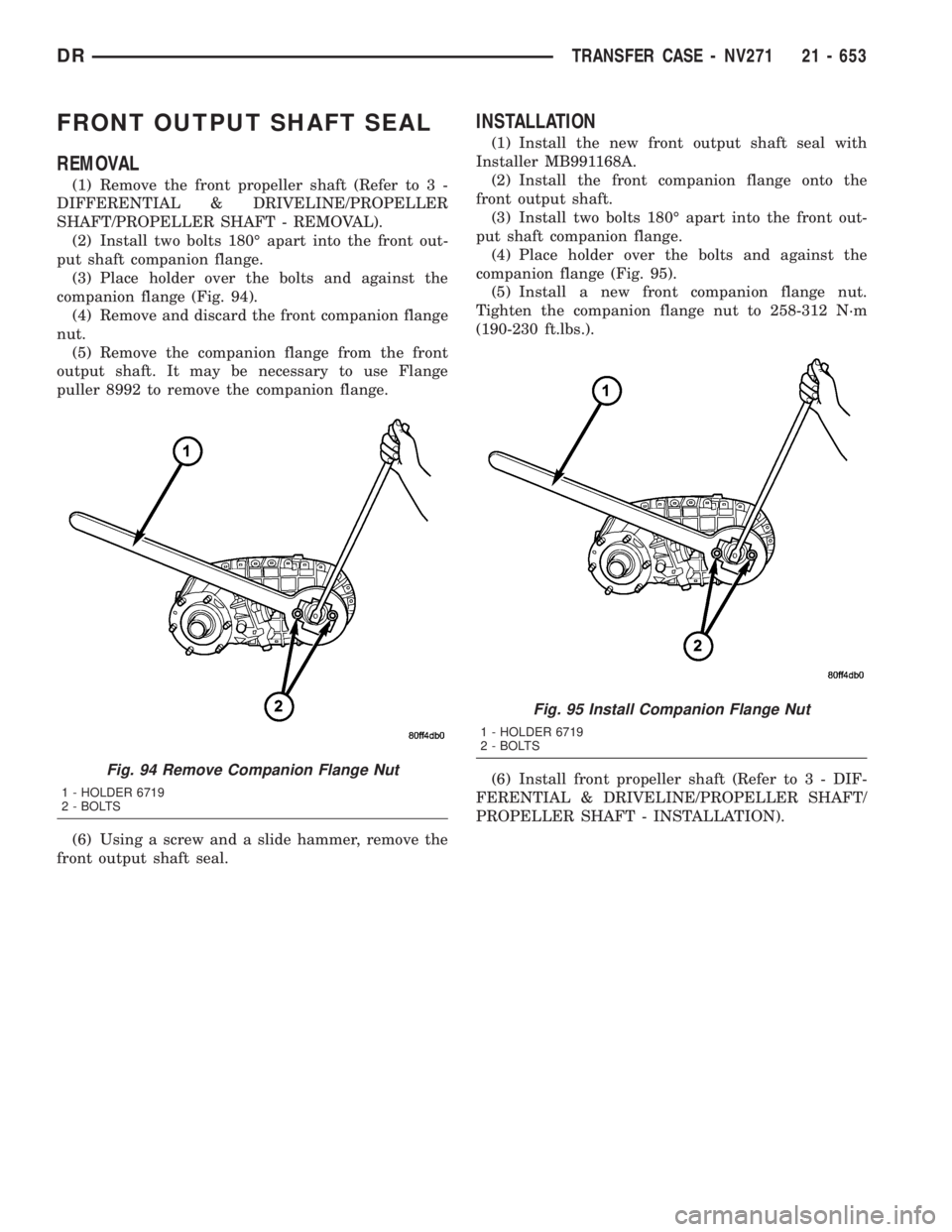
(2) Install two bolts 180É apart into the front out-
put shaft companion flange.
(3) Place holder over the bolts and against the
companion flange (Fig. 94).
(4) Remove and discard the front companion flange
nut.
(5) Remove the companion flange from the front
output shaft. It may be necessary to use Flange
puller 8992 to remove the companion flange.
(6) Using a screw and a slide hammer, remove the
front output shaft seal.
INSTALLATION
(1) Install the new front output shaft seal with
Installer MB991168A.
(2) Install the front companion flange onto the
front output shaft.
(3) Install two bolts 180É apart into the front out-
put shaft companion flange.
(4) Place holder over the bolts and against the
companion flange (Fig. 95).
(5) Install a new front companion flange nut.
Tighten the companion flange nut to 258-312 N´m
(190-230 ft.lbs.).
(6) Install front propeller shaft (Refer to 3 - DIF-
FERENTIAL & DRIVELINE/PROPELLER SHAFT/
PROPELLER SHAFT - INSTALLATION).
Fig. 94 Remove Companion Flange Nut
1 - HOLDER 6719
2 - BOLTS
Fig. 95 Install Companion Flange Nut
1 - HOLDER 6719
2 - BOLTS
DRTRANSFER CASE - NV271 21 - 653
Page 2522 of 2895
FRONT OUTPUT SHAFT SEAL
REMOVAL
(1) Remove the front propeller shaft (Refer to 3 -
DIFFERENTIAL & DRIVELINE/PROPELLER
SHAFT/PROPELLER SHAFT - REMOVAL).
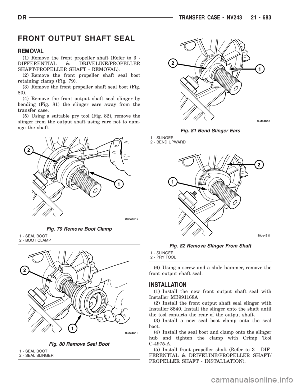
(2) Remove the front propeller shaft seal boot
retaining clamp (Fig. 79).
(3) Remove the front propeller shaft seal boot (Fig.
80).
(4) Remove the front output shaft seal slinger by
bending (Fig. 81) the slinger ears away from the
transfer case.
(5) Using a suitable pry tool (Fig. 82), remove the
slinger from the output shaft using care not to dam-
age the shaft.
(6) Using a screw and a slide hammer, remove the
front output shaft seal.
INSTALLATION
(1) Install the new front output shaft seal with
Installer MB991168A
(2) Install the front output shaft seal slinger with
Installer 8840. Install the slinger onto the shaft until
the tool contacts the rear of the output shaft.
(3) Install a new seal boot clamp onto the seal
boot.
(4) Install the seal boot and clamp onto the slinger
hub and tighten the clamp with Crimp Tool
C-4975-A.
(5) Install front propeller shaft (Refer to 3 - DIF-
FERENTIAL & DRIVELINE/PROPELLER SHAFT/
PROPELLER SHAFT - INSTALLATION).
Fig. 79 Remove Boot Clamp
1 - SEAL BOOT
2 - BOOT CLAMP
Fig. 80 Remove Seal Boot
1 - SEAL BOOT
2 - SEAL SLINGER
Fig. 81 Bend Slinger Ears
1 - SLINGER
2 - BEND UPWARD
Fig. 82 Remove Slinger From Shaft
1 - SLINGER
2-PRYTOOL
DRTRANSFER CASE - NV243 21 - 683
Page 2556 of 2895
(6) Fill transfer case to bottom edge of fill plug
opening with MopartATF +4, Automatic Transmis-
sion fluid.
(7) Install and tighten fill plug to 41-54 N´m
(30-40 ft. lbs.).
(8) Lower vehicle.
FRONT OUTPUT SHAFT SEAL
REMOVAL
(1) Remove the front propeller shaft (Refer to 3 -
DIFFERENTIAL & DRIVELINE/PROPELLER
SHAFT/PROPELLER SHAFT - REMOVAL).
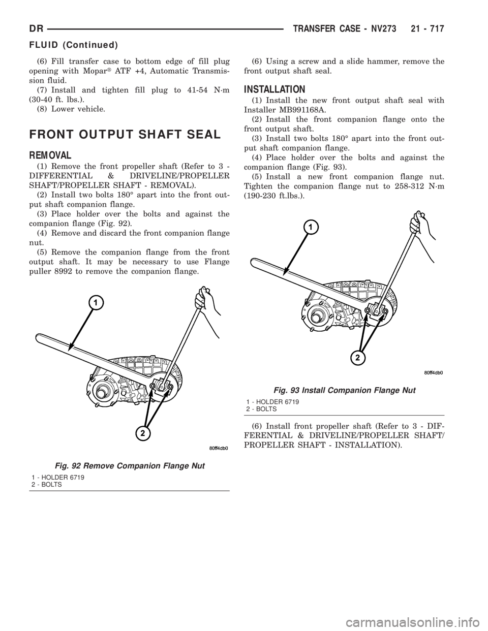
(2) Install two bolts 180É apart into the front out-
put shaft companion flange.
(3) Place holder over the bolts and against the
companion flange (Fig. 92).
(4) Remove and discard the front companion flange
nut.
(5) Remove the companion flange from the front
output shaft. It may be necessary to use Flange
puller 8992 to remove the companion flange.(6) Using a screw and a slide hammer, remove the
front output shaft seal.
INSTALLATION
(1) Install the new front output shaft seal with
Installer MB991168A.
(2) Install the front companion flange onto the
front output shaft.
(3) Install two bolts 180É apart into the front out-
put shaft companion flange.
(4) Place holder over the bolts and against the
companion flange (Fig. 93).
(5) Install a new front companion flange nut.
Tighten the companion flange nut to 258-312 N´m
(190-230 ft.lbs.).
(6) Install front propeller shaft (Refer to 3 - DIF-
FERENTIAL & DRIVELINE/PROPELLER SHAFT/
PROPELLER SHAFT - INSTALLATION).
Fig. 92 Remove Companion Flange Nut
1 - HOLDER 6719
2 - BOLTS
Fig. 93 Install Companion Flange Nut
1 - HOLDER 6719
2 - BOLTS
DRTRANSFER CASE - NV273 21 - 717
FLUID (Continued)