2003 DODGE RAM Rack and pinion
[x] Cancel search: Rack and pinionPage 2084 of 2895
INSPECTION
Inspect the planetary gear sets and annulus gears.
The planetary pinions, shafts, washers, and retaining
pins are serviceable. However, if a pinion carrier is
damaged, the entire planetary gear set must be
replaced as an assembly.
Replace the annulus gears if the teeth are chipped,
broken, or worn, or the gear is cracked. Replace the
planetary thrust plates and the tabbed thrust wash-
ers if cracked, scored or worn.
Inspect the machined surfaces of the intermediate
shaft. Be sure the oil passages are open and clear.
Replace the shaft if scored, pitted, or damaged.
Inspect the sun gear and driving shell. If either
component is worn or damaged, remove the sun gear
rear retaining ring and separate the sun gear and
thrust plate from the driving shell. Then replace the
necessary component.
Replace the sun gear as an assembly if the gear
teeth are chipped or worn. Also replace the gear as
an assembly if the bushings are scored or worn. The
sun gear bushings are not serviceable. Replace the
thrust plate if worn, or severely scored. Replace the
driving shell if distorted, cracked, or damaged in any
way.
Replace all snap-rings during geartrain assembly.
Reusing snap-rings is not recommended.
ASSEMBLY
(1) Lubricate sun gear and planetary gears with
transmission fluid during assembly. Use petroleum
jelly to lubricate intermediate shaft bushing surfaces,
thrust washers and thrust plates and to hold these
parts in place during assembly.
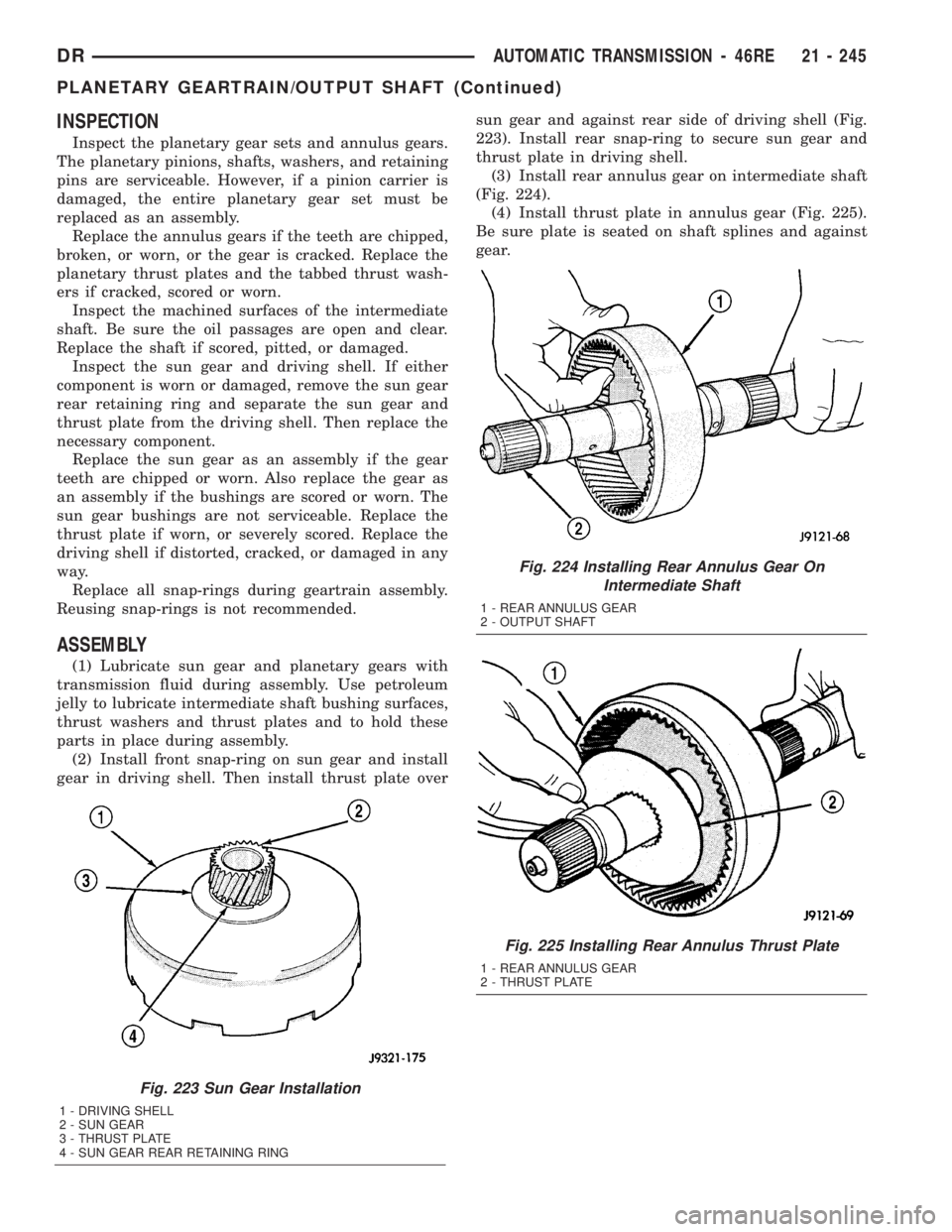
(2) Install front snap-ring on sun gear and install
gear in driving shell. Then install thrust plate oversun gear and against rear side of driving shell (Fig.
223). Install rear snap-ring to secure sun gear and
thrust plate in driving shell.
(3) Install rear annulus gear on intermediate shaft
(Fig. 224).
(4) Install thrust plate in annulus gear (Fig. 225).
Be sure plate is seated on shaft splines and against
gear.
Fig. 223 Sun Gear Installation
1 - DRIVING SHELL
2 - SUN GEAR
3 - THRUST PLATE
4 - SUN GEAR REAR RETAINING RING
Fig. 224 Installing Rear Annulus Gear On
Intermediate Shaft
1 - REAR ANNULUS GEAR
2 - OUTPUT SHAFT
Fig. 225 Installing Rear Annulus Thrust Plate
1 - REAR ANNULUS GEAR
2 - THRUST PLATE
DRAUTOMATIC TRANSMISSION - 46RE 21 - 245
PLANETARY GEARTRAIN/OUTPUT SHAFT (Continued)
Page 2245 of 2895
able. Replace any of the overdrive unit snap-rings if
distorted or damaged.
Minor nicks or scratches on components can be
smoothed with crocus cloth. However, do not attempt
to reduce severe scoring on any components with
abrasive materials. Replace severely scored compo-
nents; do not try to salvage them.
INSPECTION
Check condition of the park lock components and
the overdrive case.
Check the bushings in the overdrive case. Replace
the bushings if severely scored or worn. Also replace
the case seal if loose, distorted, or damaged.
Examine the overdrive and direct clutch discs and
plates. Replace the discs if the facing is worn,
severely scored, or burned and flaking off. Replace
the clutch plates if worn, heavily scored, or cracked.
Check the lugs on the clutch plates for wear. The
plates should slide freely in the drum. Replace the
plates or drum if binding occurs.
Check condition of the annulus gear, direct clutch
hub, clutch drum and clutch spring. Replace the gear,
hub and drum if worn or damaged. Replace the
spring if collapsed, distorted, or cracked.
Be sure the splines and lugs on the gear, drum and
hub are in good condition. The clutch plates and
discs should slide freely in these components.
Inspect the thrust bearings and spring plate.
Replace the plate if worn or scored. Replace the bear-
ings if rough, noisy, brinnelled, or worn.
Inspect the planetary gear assembly and the sun
gear and bushings. If either the sun gear or the
bushings are damaged, replace the gear and bush-
ings as an assembly. The gear and bushings are not
serviced separately.
The planetary carrier and pinions must be in good
condition. Also be sure the pinion pins are secure and in
good condition. Replace the carrier if worn or damaged.
Inspect the overrunning clutch and race. The race
surface should be smooth and free of scores. Replace
the overrunning clutch assembly or the race if either
assembly is worn or damaged in any way.
Replace the shaft pilot bushing and inner bushing
if damaged. Replace either shaft bearing if rough or
noisy. Replace the bearing snap-rings if distorted or
cracked.
Check the machined surfaces on the output shaft.
These surfaces should clean and smooth. Very minor
nicks or scratches can be smoothed with crocus cloth.
Replace the shaft if worn, scored or damaged in any way.
Inspect the output shaft bushings. The small bush-
ing is the intermediate shaft pilot bushing. The large
bushing is the overrunning clutch hub bushing.
Replace either bushing if scored, pitted, cracked, or
worn.
ASSEMBLY
GEARTRAIN AND DIRECT CLUTCH
(1) Soak direct clutch and overdrive clutch discs in
MopartATF +4, Automatic Transmission fluid. Allow
discs to soak for 10-20 minutes.
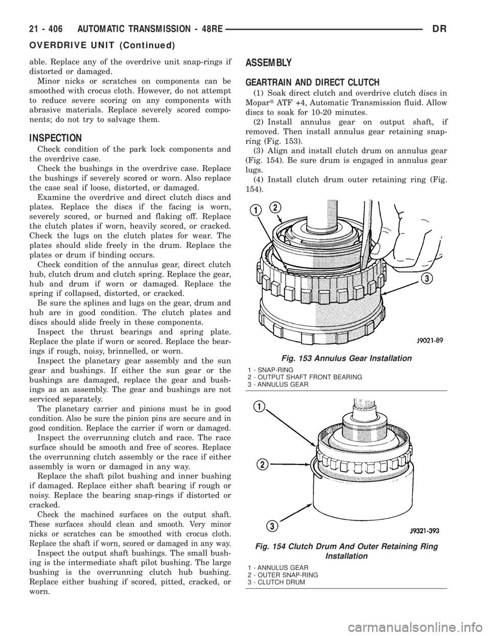
(2) Install annulus gear on output shaft, if
removed. Then install annulus gear retaining snap-
ring (Fig. 153).
(3) Align and install clutch drum on annulus gear
(Fig. 154). Be sure drum is engaged in annulus gear
lugs.
(4) Install clutch drum outer retaining ring (Fig.
154).
Fig. 153 Annulus Gear Installation
1 - SNAP-RING
2 - OUTPUT SHAFT FRONT BEARING
3 - ANNULUS GEAR
Fig. 154 Clutch Drum And Outer Retaining Ring
Installation
1 - ANNULUS GEAR
2 - OUTER SNAP-RING
3 - CLUTCH DRUM
21 - 406 AUTOMATIC TRANSMISSION - 48REDR
OVERDRIVE UNIT (Continued)
Page 2261 of 2895
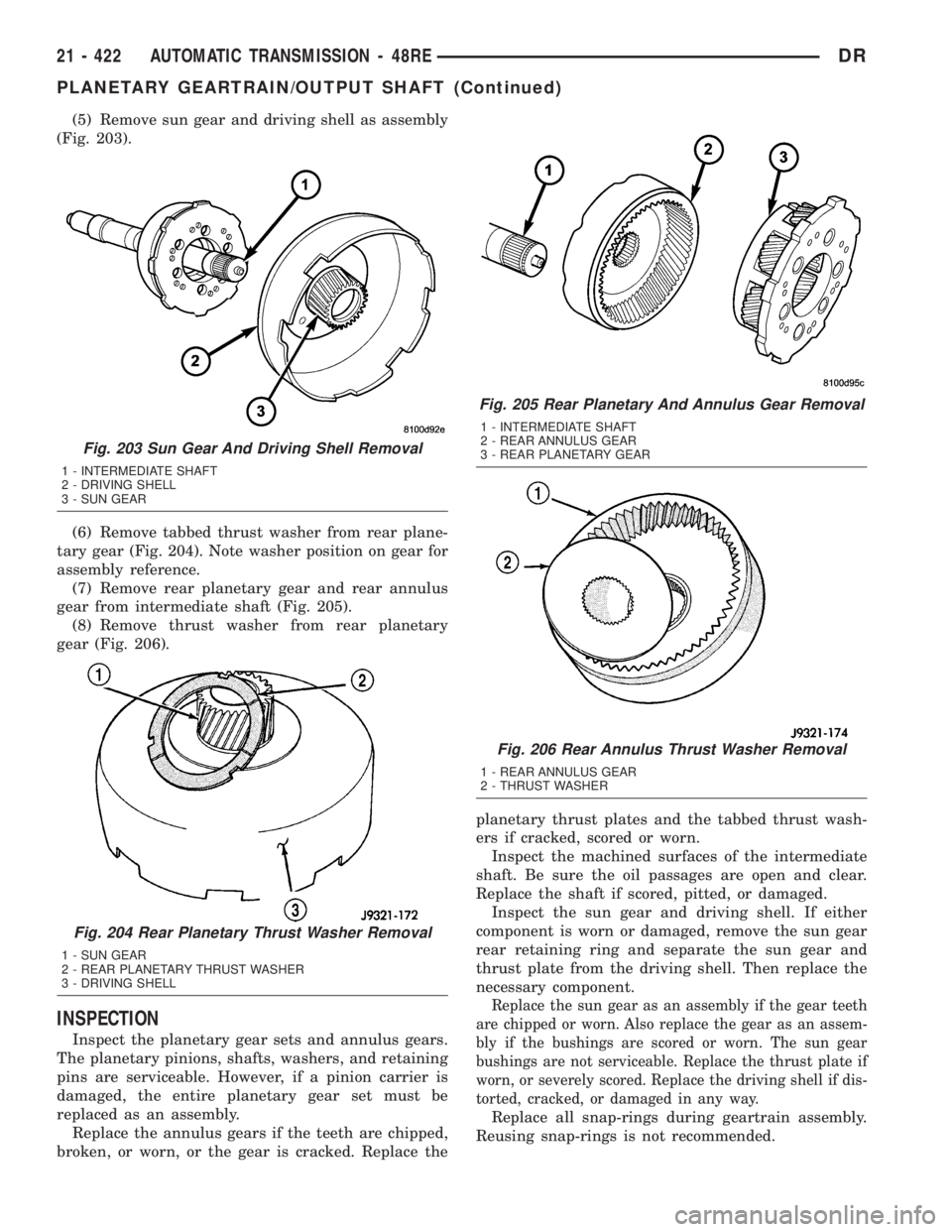
(5) Remove sun gear and driving shell as assembly
(Fig. 203).
(6) Remove tabbed thrust washer from rear plane-
tary gear (Fig. 204). Note washer position on gear for
assembly reference.
(7) Remove rear planetary gear and rear annulus
gear from intermediate shaft (Fig. 205).
(8) Remove thrust washer from rear planetary
gear (Fig. 206).
INSPECTION
Inspect the planetary gear sets and annulus gears.
The planetary pinions, shafts, washers, and retaining
pins are serviceable. However, if a pinion carrier is
damaged, the entire planetary gear set must be
replaced as an assembly.
Replace the annulus gears if the teeth are chipped,
broken, or worn, or the gear is cracked. Replace theplanetary thrust plates and the tabbed thrust wash-
ers if cracked, scored or worn.
Inspect the machined surfaces of the intermediate
shaft. Be sure the oil passages are open and clear.
Replace the shaft if scored, pitted, or damaged.
Inspect the sun gear and driving shell. If either
component is worn or damaged, remove the sun gear
rear retaining ring and separate the sun gear and
thrust plate from the driving shell. Then replace the
necessary component.
Replace the sun gear as an assembly if the gear teeth
are chipped or worn. Also replace the gear as an assem-
bly if the bushings are scored or worn. The sun gear
bushings are not serviceable. Replace the thrust plate if
worn, or severely scored. Replace the driving shell if dis-
torted, cracked, or damaged in any way.
Replace all snap-rings during geartrain assembly.
Reusing snap-rings is not recommended.
Fig. 203 Sun Gear And Driving Shell Removal
1 - INTERMEDIATE SHAFT
2 - DRIVING SHELL
3 - SUN GEAR
Fig. 204 Rear Planetary Thrust Washer Removal
1 - SUN GEAR
2 - REAR PLANETARY THRUST WASHER
3 - DRIVING SHELL
Fig. 205 Rear Planetary And Annulus Gear Removal
1 - INTERMEDIATE SHAFT
2 - REAR ANNULUS GEAR
3 - REAR PLANETARY GEAR
Fig. 206 Rear Annulus Thrust Washer Removal
1 - REAR ANNULUS GEAR
2 - THRUST WASHER
21 - 422 AUTOMATIC TRANSMISSION - 48REDR
PLANETARY GEARTRAIN/OUTPUT SHAFT (Continued)
Page 2412 of 2895
DISASSEMBLY
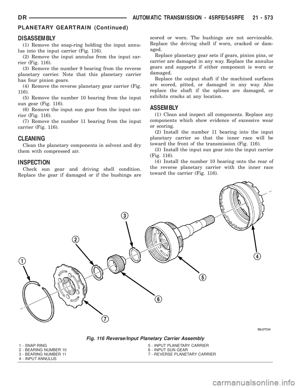
(1) Remove the snap-ring holding the input annu-
lus into the input carrier (Fig. 116).
(2) Remove the input annulus from the input car-
rier (Fig. 116).
(3) Remove the number 9 bearing from the reverse
planetary carrier. Note that this planetary carrier
has four pinion gears.
(4) Remove the reverse planetary gear carrier (Fig.
116).
(5) Remove the number 10 bearing from the input
sun gear (Fig. 116).
(6) Remove the input sun gear from the input car-
rier (Fig. 116).
(7) Remove the number 11 bearing from the input
carrier (Fig. 116).
CLEANING
Clean the planetary components in solvent and dry
them with compressed air.
INSPECTION
Check sun gear and driving shell condition.
Replace the gear if damaged or if the bushings arescored or worn. The bushings are not serviceable.
Replace the driving shell if worn, cracked or dam-
aged.
Replace planetary gear sets if gears, pinion pins, or
carrier are damaged in any way. Replace the annulus
gears and supports if either component is worn or
damaged.
Replace the output shaft if the machined surfaces
are scored, pitted, or damaged in any way. Also
replace the shaft if the splines are damaged, or
exhibits cracks at any location.
ASSEMBLY
(1) Clean and inspect all components. Replace any
components which show evidence of excessive wear
or scoring.
(2) Install the number 11 bearing into the input
planetary carrier so that the inner race will be
toward the front of the transmission (Fig. 116).
(3) Install the input sun gear into the input carrier
(Fig. 116).
(4) Install the number 10 bearing onto the rear of
the reverse planetary carrier with the inner race
toward the carrier (Fig. 116).
Fig. 116 Reverse/Input Planetary Carrier Assembly
1 - SNAP-RING 5 - INPUT PLANETARY CARRIER
2 - BEARING NUMBER 10 6 - INPUT SUN GEAR
3 - BEARING NUMBER 11 7 - REVERSE PLANETARY CARRIER
4 - INPUT ANNULUS
DRAUTOMATIC TRANSMISSION - 45RFE/545RFE 21 - 573
PLANETARY GEARTRAIN (Continued)
Page 2441 of 2895
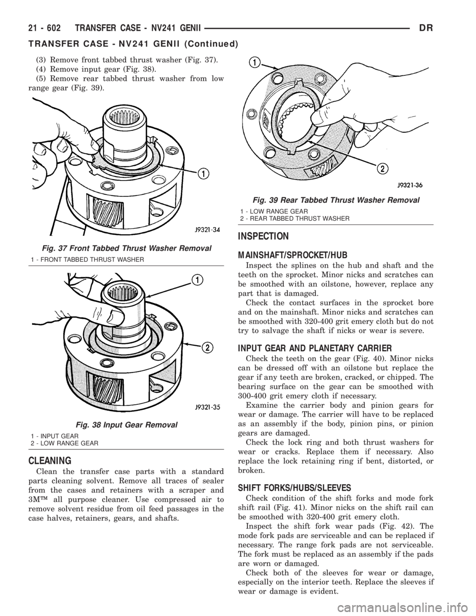
(3) Remove front tabbed thrust washer (Fig. 37).
(4) Remove input gear (Fig. 38).
(5) Remove rear tabbed thrust washer from low
range gear (Fig. 39).
CLEANING
Clean the transfer case parts with a standard
parts cleaning solvent. Remove all traces of sealer
from the cases and retainers with a scraper and
3MŸ all purpose cleaner. Use compressed air to
remove solvent residue from oil feed passages in the
case halves, retainers, gears, and shafts.
INSPECTION
MAINSHAFT/SPROCKET/HUB
Inspect the splines on the hub and shaft and the
teeth on the sprocket. Minor nicks and scratches can
be smoothed with an oilstone, however, replace any
part that is damaged.
Check the contact surfaces in the sprocket bore
and on the mainshaft. Minor nicks and scratches can
be smoothed with 320-400 grit emery cloth but do not
try to salvage the shaft if nicks or wear is severe.
INPUT GEAR AND PLANETARY CARRIER
Check the teeth on the gear (Fig. 40). Minor nicks
can be dressed off with an oilstone but replace the
gear if any teeth are broken, cracked, or chipped. The
bearing surface on the gear can be smoothed with
300-400 grit emery cloth if necessary.
Examine the carrier body and pinion gears for
wear or damage. The carrier will have to be replaced
as an assembly if the body, pinion pins, or pinion
gears are damaged.
Check the lock ring and both thrust washers for
wear or cracks. Replace them if necessary. Also
replace the lock retaining ring if bent, distorted, or
broken.
SHIFT FORKS/HUBS/SLEEVES
Check condition of the shift forks and mode fork
shift rail (Fig. 41). Minor nicks on the shift rail can
be smoothed with 320-400 grit emery cloth.
Inspect the shift fork wear pads (Fig. 42). The
mode fork pads are serviceable and can be replaced if
necessary. The range fork pads are not serviceable.
The fork must be replaced as an assembly if the pads
are worn or damaged.
Check both of the sleeves for wear or damage,
especially on the interior teeth. Replace the sleeves if
wear or damage is evident.
Fig. 37 Front Tabbed Thrust Washer Removal
1 - FRONT TABBED THRUST WASHER
Fig. 38 Input Gear Removal
1 - INPUT GEAR
2 - LOW RANGE GEAR
Fig. 39 Rear Tabbed Thrust Washer Removal
1 - LOW RANGE GEAR
2 - REAR TABBED THRUST WASHER
21 - 602 TRANSFER CASE - NV241 GENIIDR
TRANSFER CASE - NV241 GENII (Continued)
Page 2475 of 2895
Examine the carrier body and pinion gears for
wear or damage. Check the pinion gear thrust wash-
ers on the pinon pins for damage. The carrier will
have to be replaced as an assembly if the body, pin-
ion pins, or pinion gears are damaged.
Check the lock ring and both thrust washers for
wear or cracks. Replace them if necessary. Also
replace the lock retaining ring if bent, distorted, or
broken.
SHIFT FORKS/HUBS/SLEEVES
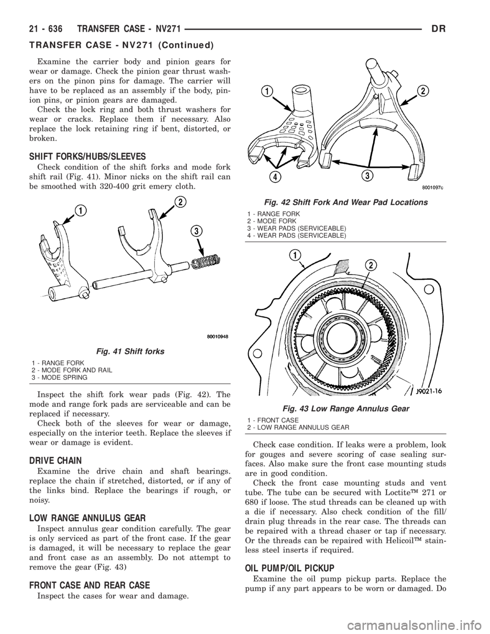
Check condition of the shift forks and mode fork
shift rail (Fig. 41). Minor nicks on the shift rail can
be smoothed with 320-400 grit emery cloth.
Inspect the shift fork wear pads (Fig. 42). The
mode and range fork pads are serviceable and can be
replaced if necessary.
Check both of the sleeves for wear or damage,
especially on the interior teeth. Replace the sleeves if
wear or damage is evident.
DRIVE CHAIN
Examine the drive chain and shaft bearings.
replace the chain if stretched, distorted, or if any of
the links bind. Replace the bearings if rough, or
noisy.
LOW RANGE ANNULUS GEAR
Inspect annulus gear condition carefully. The gear
is only serviced as part of the front case. If the gear
is damaged, it will be necessary to replace the gear
and front case as an assembly. Do not attempt to
remove the gear (Fig. 43)
FRONT CASE AND REAR CASE
Inspect the cases for wear and damage.Check case condition. If leaks were a problem, look
for gouges and severe scoring of case sealing sur-
faces. Also make sure the front case mounting studs
are in good condition.
Check the front case mounting studs and vent
tube. The tube can be secured with LoctiteŸ 271 or
680 if loose. The stud threads can be cleaned up with
a die if necessary. Also check condition of the fill/
drain plug threads in the rear case. The threads can
be repaired with a thread chaser or tap if necessary.
Or the threads can be repaired with HelicoilŸ stain-
less steel inserts if required.
OIL PUMP/OIL PICKUP
Examine the oil pump pickup parts. Replace the
pump if any part appears to be worn or damaged. Do
Fig. 41 Shift forks
1 - RANGE FORK
2 - MODE FORK AND RAIL
3 - MODE SPRING
Fig. 42 Shift Fork And Wear Pad Locations
1 - RANGE FORK
2 - MODE FORK
3 - WEAR PADS (SERVICEABLE)
4 - WEAR PADS (SERVICEABLE)
Fig. 43 Low Range Annulus Gear
1 - FRONT CASE
2 - LOW RANGE ANNULUS GEAR
21 - 636 TRANSFER CASE - NV271DR
TRANSFER CASE - NV271 (Continued)
Page 2508 of 2895
Examine the carrier body and pinion gears for
wear or damage. The carrier will have to be replaced
as an assembly if the body, pinion pins, or pinion
gears are damaged.
Check the lock ring and both thrust washers for
wear or cracks. Replace them if necessary. Also
replace the lock retaining ring if bent, distorted, or
broken.
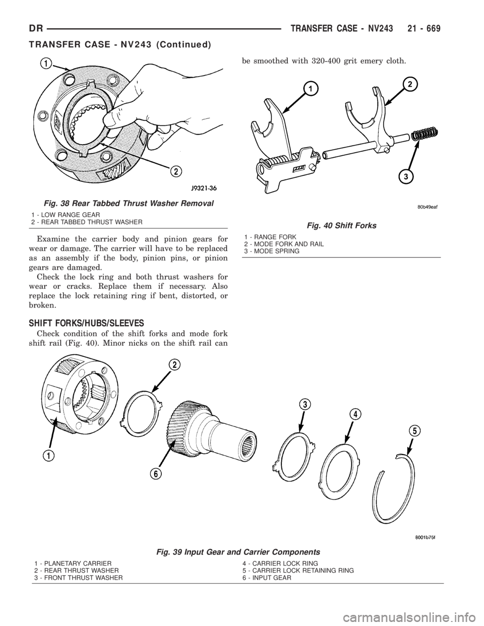
SHIFT FORKS/HUBS/SLEEVES
Check condition of the shift forks and mode fork
shift rail (Fig. 40). Minor nicks on the shift rail canbe smoothed with 320-400 grit emery cloth.
Fig. 39 Input Gear and Carrier Components
1 - PLANETARY CARRIER 4 - CARRIER LOCK RING
2 - REAR THRUST WASHER 5 - CARRIER LOCK RETAINING RING
3 - FRONT THRUST WASHER 6 - INPUT GEAR
Fig. 38 Rear Tabbed Thrust Washer Removal
1 - LOW RANGE GEAR
2 - REAR TABBED THRUST WASHER
Fig. 40 Shift Forks
1 - RANGE FORK
2 - MODE FORK AND RAIL
3 - MODE SPRING
DRTRANSFER CASE - NV243 21 - 669
TRANSFER CASE - NV243 (Continued)
Page 2538 of 2895
INSPECTION
MAINSHAFT/SPROCKET/HUB INSPECTION
Inspect the splines on the hub and shaft and the
teeth on the sprocket. Minor nicks and scratches can
be smoothed with an oilstone. However, replace any
part that is damaged.
Check the contact surfaces in the sprocket bore
and on the mainshaft. Minor nicks and scratches can
be smoothed with 320-400 grit emery cloth but do not
try to salvage the shaft if nicks or wear is severe.
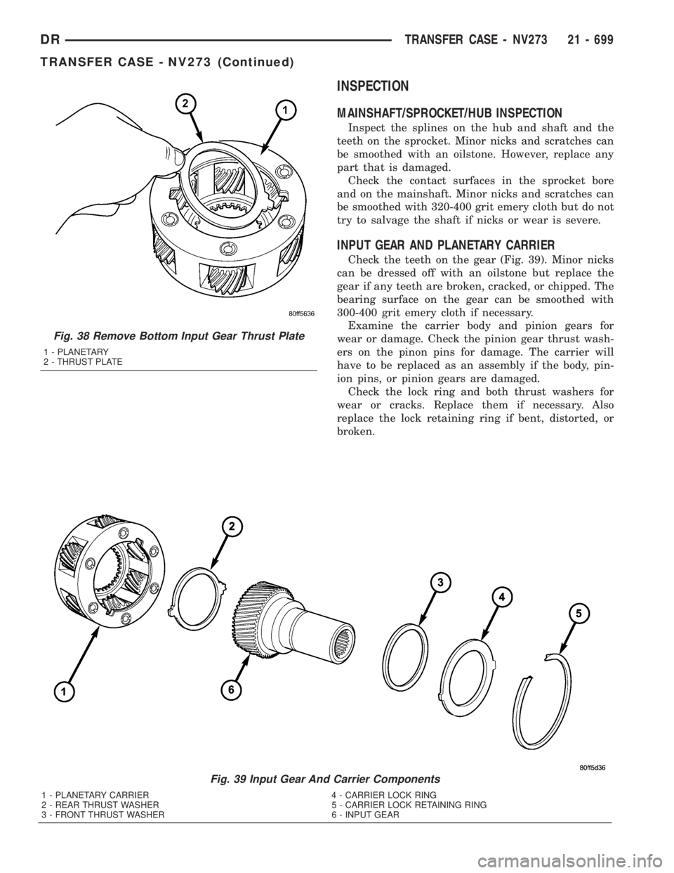
INPUT GEAR AND PLANETARY CARRIER
Check the teeth on the gear (Fig. 39). Minor nicks
can be dressed off with an oilstone but replace the
gear if any teeth are broken, cracked, or chipped. The
bearing surface on the gear can be smoothed with
300-400 grit emery cloth if necessary.
Examine the carrier body and pinion gears for
wear or damage. Check the pinion gear thrust wash-
ers on the pinon pins for damage. The carrier will
have to be replaced as an assembly if the body, pin-
ion pins, or pinion gears are damaged.
Check the lock ring and both thrust washers for
wear or cracks. Replace them if necessary. Also
replace the lock retaining ring if bent, distorted, or
broken.
Fig. 39 Input Gear And Carrier Components
1 - PLANETARY CARRIER 4 - CARRIER LOCK RING
2 - REAR THRUST WASHER 5 - CARRIER LOCK RETAINING RING
3 - FRONT THRUST WASHER 6 - INPUT GEAR
Fig. 38 Remove Bottom Input Gear Thrust Plate
1 - PLANETARY
2 - THRUST PLATE
DRTRANSFER CASE - NV273 21 - 699
TRANSFER CASE - NV273 (Continued)