2003 DODGE RAM key battery
[x] Cancel search: key batteryPage 463 of 2895

IGNITION COIL RESISTANCE - 3.7L V-6
PRIMARY RESISTANCE
21-27ÉC (70-80ÉF)SECONDARY
RESISTANCE 21-27ÉC
(70-80ÉF)
0.6 - 0.9 Ohms 6,000 - 9,000 Ohms
IGNITION COIL RESISTANCE - 4.7L V-8
PRIMARY
RESISTANCE 21-27ÉC
(70-80ÉF)SECONDARY
RESISTANCE 21-27ÉC
(70-80ÉF)
0.6 - 0.9 Ohms 6,000 - 9,000 Ohms
IGNITION COIL RESISTANCE - 5.7L V-8
PRIMARY RESISTANCE @ 21-27ÉC (70-80ÉF)
0.558 - 0.682 Ohms
(Plus or Minus 10% @ 70-80É F)
IGNITION COIL RESISTANCE - 5.9L
COIL MANUFACTURERPRIMARY RESISTANCE
21-27ÉC (70-80ÉF)SECONDARY RESISTANCE 21-27ÉC
(70-80ÉF)
Diamond 0.97 - 1.18 Ohms 11,300 - 15,300 Ohms
Toyodenso 0.95 - 1.20 Ohms 11,300 - 13,300 Ohms
IGNITION COIL RESISTANCE ± 8.0L V-10
ENGINE
Primary Resistance: 0.53-0.65 Ohms. Test across the
primary connector. Refer to text for test procedures.
Secondary Resistance: 10.9-14.7K Ohms. Test across
the individual coil towers. Refer to text for test
procedures.
IGNITION TIMING
Ignition timing is not adjustable on any engine.
AUTOMATIC SHUT DOWN
RELAY
DESCRIPTION - PCM OUTPUT
The 5±pin, 12±volt, Automatic Shutdown (ASD)
relay is located in the Power Distribution Center
(PDC). Refer to label on PDC cover for relay location.
OPERATION
OPERATION - PCM OUTPUT
The ASD relay supplies battery voltage (12+ volts)
to the fuel injectors and ignition coil(s). With certain
emissions packages it also supplies 12±volts to the
oxygen sensor heating elements.The ground circuit for the coil within the ASD
relay is controlled by the Powertrain Control Module
(PCM). The PCM operates the ASD relay by switch-
ing its ground circuit on and off.
The ASD relay will be shut±down, meaning the
12±volt power supply to the ASD relay will be de-ac-
tivated by the PCM if:
²the ignition key is left in the ON position. This
is if the engine has not been running for approxi-
mately 1.8 seconds.
²there is a crankshaft position sensor signal to
the PCM that is lower than pre-determined values.
OPERATION - ASD SENSE - PCM INPUT
A 12 volt signal at this input indicates to the PCM
that the ASD has been activated. The relay is used to
connect the oxygen sensor heater element, ignition
coil and fuel injectors to 12 volt + power supply.
This input is used only to sense that the ASD relay
is energized. If the Powertrain Control Module
(PCM) does not see 12 volts at this input when the
ASD should be activated, it will set a Diagnostic
Trouble Code (DTC).
8I - 6 IGNITION CONTROLDR
IGNITION CONTROL (Continued)
Page 479 of 2895

4.7L V-8
Battery voltage is supplied to the 8 individual igni-
tion coils from the ASD relay. The Powertrain Con-
trol Module (PCM) opens and closes each ignition coil
ground circuit at a determined time for ignition coil
operation.
Base ignition timing is not adjustable.By con-
trolling the coil ground circuit, the PCM is able to set
the base timing and adjust the ignition timing
advance. This is done to meet changing engine oper-
ating conditions.
The ignition coil is not oil filled. The windings are
embedded in an epoxy compound. This provides heat
and vibration resistance that allows the ignition coil
to be mounted on the engine.
Because of coil design, spark plug cables (second-
ary cables) are not used with the 4.7L V-8 engine.
5.7L V-8
The ignition system is controlled by the Powertrain
Control Module (PCM) on all engines.
A ªwasted sparkº system is used on the 5.7L
engine combining paired, or dual-firing coils, and 2
spark plugs per cylinder. The coils and spark plugs
are connected with paired, secondary high-voltage
cables.
Each cylinder is equipped with 1 dual-output coil.
Meaning one coil mounts directly over one of the
dual spark plugs for 1 high-voltage output. A second
high-voltage output is supplied directly from the
same coil (using a plug cable) to one of the dual
spark plugs on a corresponding (paired) cylinder on
the opposite cylinder bank.
Each coil fires 2 spark plugs simultaneously on
each of the cylinder banks (one cylinder on compres-
sion stroke and one cylinder on exhaust stroke).
EXAMPLE :When the #1 cylinder is on compression
stroke and ready for spark, the #1 coil will fire one of
the dual spark plugs on the #1 cylinder (directly
below the coil). The other dual spark plug on the #1
cylinder will be fired by the #6 coil. At the same
time, the #1 coil will fire a ªwasted sparkº to one of
the dual spark plugs at the #6 cylinder as coil #6 also
fires a ªwasted sparkº to one of the dual spark plugs
at the #6 cylinder.
The firing order is paired at cylinders 1/6, 2/3, 4/7,
5/8. Basic cylinder firing order is 1±8±4±3±6±5±7±2.
Battery voltage is supplied to all of the ignition
coils positive terminals from the ASD relay. If the
PCM does not see a signal from the crankshaft and
camshaft sensors (indicating the ignition key is ON
but the engine is not running), it will shut down the
ASD circuit.
Base ignition timing is not adjustable on the
5.7L V-8 engine.By controlling the coil ground cir-
cuits, the PCM is able to set the base timing andadjust the ignition timing advance. This is done to
meet changing engine operating conditions.
The PCM adjusts ignition timing based on inputs it
receives from:
²The engine coolant temperature sensor
²The crankshaft position sensor (engine speed)
²The camshaft position sensor (crankshaft posi-
tion)
²The manifold absolute pressure (MAP) sensor
²The throttle position sensor
²Transmission gear selection
5.9L V-8
A single ignition coil is used. The Powertrain Con-
trol Module (PCM) opens and closes the ignition coil
ground circuit for ignition coil operation.
Battery voltage is supplied to the ignition coil pos-
itive terminal from the ASD relay. If the PCM does
not see a signal from the crankshaft and camshaft
sensors (indicating the ignition key is ON but the
engine is not running), it will shut down the ASD cir-
cuit.
Base ignition timing is not adjustable on any
engine.By controlling the coil ground circuit, the
PCM is able to set the base timing and adjust the
ignition timing advance. This is done to meet chang-
ing engine operating conditions.
Conventional spark plug cables (secondary cables)
are used with the 5.9L V-8 engine.
8.0L V-10
When one of the 5 independent coils discharges, it
fires two paired cylinders at the same time (one cyl-
inder on compression stroke and the other cylinder
on exhaust stroke).
Coil firing is paired together on cylinders:
²Number 5 and 10
²Number 9 and 8
²Number 1 and 6
²Number 7 and 4
²Number 3 and 2
The ignition system is controlled by the Powertrain
Control Module (PCM) on all engines.
Battery voltage is supplied to all of the ignition
coils positive terminals from the ASD relay. If the
PCM does not see a signal from the crankshaft and
camshaft sensors (indicating the ignition key is ON
but the engine is not running), it will shut down the
ASD circuit.
Conventional spark plug cables (secondary cables)
are used with the 8.0L V-10 engine.
Base ignition timing is not adjustable on the
8.0L V-10 engine.By controlling the coil ground cir-
cuits, the PCM is able to set the base timing and
adjust the ignition timing advance. This is done to
meet changing engine operating conditions.
8I - 22 IGNITION CONTROLDR
IGNITION COIL (Continued)
Page 482 of 2895

(6)If necessary, install throttle body air tube or box.
KNOCK SENSOR
DESCRIPTION
The sensors are used only with 3.7L V-6, 4.7L V-8
and 5.7L V-8 engines. On 3.7L V-6 and 4.7L V-8
engines, the 2 knock sensors are bolted into the cyl-
inder block under the intake manifold.
On 5.7L V-8 engines, 2 knock sensors are also
used. These are bolted into each side of the cylinder
block (outside) under the exhaust manifold.
OPERATION
3.7L V-6 / 4.7L V-8 / 5.7L V-8 Engines Only
Two knock sensors are used; one for each cylinder
bank. When the knock sensor detects a knock in one
of the cylinders on the corresponding bank, it sends
an input signal to the Powertrain Control Module
(PCM). In response, the PCM retards ignition timing
for all cylinders by a scheduled amount.
Knock sensors contain a piezoelectric material
which constantly vibrates and sends an input voltage
(signal) to the PCM while the engine operates. As the
intensity of the crystal's vibration increases, the
knock sensor output voltage also increases.The voltage signal produced by the knock sensor
increases with the amplitude of vibration. The PCM
receives the knock sensor voltage signal as an input.
If the signal rises above a predetermined level, the
PCM will store that value in memory and retard
ignition timing to reduce engine knock. If the knock
sensor voltage exceeds a preset value, the PCM
retards ignition timing for all cylinders. It is not a
selective cylinder retard.
The PCM ignores knock sensor input during engine
idle conditions. Once the engine speed exceeds a
specified value, knock retard is allowed.
Knock retard uses its own short term and long
term memory program.
Long term memory stores previous detonation
information in its battery-backed RAM. The maxi-
mum authority that long term memory has over tim-
ing retard can be calibrated.
Short term memory is allowed to retard timing up
to a preset amount under all operating conditions (as
long as rpm is above the minimum rpm) except at
Wide Open Throttle (WOT). The PCM, using short
term memory, can respond quickly to retard timing
when engine knock is detected. Short term memory
is lost any time the ignition key is turned off.
NOTE: Over or under tightening the sensor mount-
ing bolts will affect knock sensor performance, pos-
sibly causing improper spark control. Always use
the specified torque when installing the knock sen-
sors.
REMOVAL
3.7L V-6 / 4.7L V-8
The 2 knock sensors are bolted into the cylinder
block under the intake manifold (Fig. 39). or (Fig.
40).
NOTE: The left sensor is identified by an identifica-
tion tag (LEFT). It is also identified by a larger bolt
head. The Powertrain Control Module (PCM) must
have and know the correct sensor left/right posi-
tions. Do not mix the sensor locations.
(1) Disconnect knock sensor dual pigtail harness
from engine wiring harness. This connection is made
near rear of engine.
(2) Remove intake manifold. Refer to Engine sec-
tion.
(3) Remove sensor mounting bolts (Fig. 39), or
(Fig. 40). Note foam strip on bolt threads. This foam
is used only to retain the bolts to sensors for plant
assembly. It is not used as a sealant. Do not apply
any adhesive, sealant or thread locking compound to
these bolts.
Fig. 38 SPARK PLUG CABLE ORDER - 8.0L V-10
DRIGNITION CONTROL 8I - 25
IGNITION COIL (Continued)
Page 496 of 2895

molded plastic cluster housing serves as the carrier
for the cluster circuit board and circuitry, the cluster
connector receptacles, the RKE interface connector,
the gauges, a Light Emitting Diode (LED) for each
cluster indicator, two VFD units, an audible tone
generator, the cluster overlay, the gauge pointers, the
odometer/trip odometer switch and the switch button.
The cluster overlay is a laminated plastic unit. The
dark, visible, outer surface of the overlay is marked
with all of the gauge dial faces and graduations, but
this layer is also translucent. The darkness of this
outer layer prevents the cluster from appearing clut-
tered or busy by concealing the cluster indicators
that are not illuminated, while the translucence of
this layer allows those indicators and icons that are
illuminated to be readily visible. The underlying
layer of the overlay is opaque and allows light from
the LED for each of the various indicators and the
incandescent illumination lamps behind it to be visi-
ble through the outer layer of the overlay only
through predetermined stencil-like cutouts. A rectan-
gular opening in the overlay at the base of both the
speedometer and tachometer dial faces has a smoked
clear lens through which the illuminated VFD units
can be viewed.
Several versions of the EMIC module are offered
on this model. These versions accommodate all of the
variations of optional equipment and regulatory
requirements for the various markets in which the
vehicle will be offered. The microprocessor-based
EMIC utilizes integrated circuitry and information
carried on the Programmable Communications Inter-
face (PCI) data bus network along with several hard
wired analog and multiplexed inputs to monitor sen-
sors and switches throughout the vehicle. In response
to those inputs, the internal circuitry and program-
ming of the EMIC allow it to control and integrate
many electronic functions and features of the vehicle
through both hard wired outputs and the transmis-
sion of electronic message outputs to other electronic
modules in the vehicle over the PCI data bus. (Refer
to 8 - ELECTRICAL/ELECTRONIC CONTROL
MODULES/COMMUNICATION - DESCRIPTION -
PCI BUS).
Besides typical instrument cluster gauge and indi-
cator support, the electronic functions and features
that the EMIC supports or controls include the fol-
lowing:
²Audible Warnings- The EMIC electronic cir-
cuit board is equipped with an audible tone generator
and programming that allows it to provide various
audible alerts to the vehicle operator, including
chime tones and beep tones. An electromechanical
relay is also soldered onto the circuit board to pro-
duce audible clicks that emulate the sound of a con-
ventional turn signal or hazard warning flasher.(Refer to 8 - ELECTRICAL/CHIME/BUZZER -
DESCRIPTION).
²Brake Lamp Control- The EMIC provides
electronic brake lamp request messages to the Front
Control Module (FCM) located on the Integrated
Power Module (IPM) for brake lamp control, exclud-
ing control of the Center High Mounted Stop Lamp
(CHMSL), which remains controlled by a direct hard
wired output of the brake lamp switch.
²Brake Transmission Shift Interlock Control
- The EMIC monitors inputs from the brake lamp
switch, ignition switch, and the Transmission Range
Sensor (TRS), then controls a high-side driver output
to operate the Brake Transmission Shift Interlock
(BTSI) solenoid that locks and unlocks the automatic
transmission gearshift selector lever on the steering
column.
²Cargo Lamp Control- The EMIC provides
direct control of cargo lamp operation with a load
shedding (battery saver) feature which will automat-
ically turn off the cargo lamp if it remains on after a
timed interval.
²Central Locking- The EMIC provides support
for the central locking feature of the power lock sys-
tem. This feature will lock or unlock all doors based
upon the input from the door cylinder lock switch.
Door cylinder lock switches are used only on models
equipped with the optional Vehicle Theft Security
System (VTSS).
²Door Lock Inhibit- The EMIC inhibits locking
of the doors with the power lock switch when the key
is in the ignition switch and the driver side front
door is ajar. However, operation of the door locks is
not inhibited under the same conditions when the
Lock button of the optional RKE transmitter is
depressed.
²Enhanced Accident Response- The EMIC
monitors an input from the Airbag Control Module
(ACM) and, following an airbag deployment, will
immediately disable the power lock output, unlock all
doors by activating the power unlock output, then
enables the power lock output if the power lock
switch input remains inactive for two seconds. This
feature, like all other enhanced accident response
features, is dependent upon a functional vehicle elec-
trical system following the vehicle impact event.
²Exterior Lighting Control- The EMIC pro-
vides electronic head lamp and/or park lamp request
messages to the Front Control Module (FCM) located
on the Integrated Power Module (IPM) for the appro-
priate exterior lamp control of standard head and
park lamps, as well as optional front fog lamps. This
includes support for headlamp beam selection and
the optical horn feature, also known as flash-to-pass.
²Exterior Lighting Fail-safe- In the absence of
a headlamp switch input, the EMIC will turn on the
DRINSTRUMENT CLUSTER 8J - 3
INSTRUMENT CLUSTER (Continued)
Page 497 of 2895

cluster illumination lamps and provide electronic
headlamp low beam and park lamp request messages
to the Front Control Module (FCM) located on the
Integrated Power Module (IPM) for default exterior
lamp operation. The FCM will also provide default
park lamp and headlamp low beam operation and the
EMIC will turn on the cluster illumination lamps if
there is a failure of the electronic data bus commu-
nication between the EMIC and the FCM.
²Heated Seat Control- The EMIC monitors
inputs from the ignition switch and electronic engine
speed messages from the Powertrain Control Module
(PCM) to control a high side driver output to the
heated seat switch Light Emitting Diode (LED) indi-
cators. This input allows the heated seat switches to
wake up the heated seat module if the switch is actu-
ated. The EMIC will de-energize the heated seat
switch LED indicators, which deactivates the heated
seat system, if the ignition switch is turned to any
position except On or Start, or if the engine speed
message indicates zero. (Refer to 8 - ELECTRICAL/
HEATED SEATS - DESCRIPTION).
²Interior Lamp Load Shedding- The EMIC
provides a battery saver feature which will automat-
ically turn off all interior lamps that remain on after
a timed interval of about fifteen minutes.
²Interior Lamps - Enhanced Accident
Response- The EMIC monitors inputs from the Air-
bag Control Module (ACM) and the Powertrain Con-
trol Module (PCM) to automatically turn on the
interior lighting after an airbag deployment event
ten seconds after the vehicle speed is zero. The inte-
rior lighting remains illuminated until the ignition
switch is turned to the Off position, at which time
the interior lighting returns to normal operation and
control. This feature, like all other enhanced accident
response features, is dependent upon a functional
vehicle electrical system following the vehicle impact
event.
²Interior Lighting Control- The EMIC moni-
tors inputs from the interior lighting switch, the door
ajar switches, the cargo lamp switch, the reading
lamp switches, and the Remote Keyless Entry (RKE)
module to provide courtesy lamp control. This
includes support for timed illuminated entry with
theater-style fade-to-off and courtesy illumination
defeat features.
²Lamp Out Indicator Control- The EMIC
monitors electronic lamp outage messages from the
Front Control Module (FCM) located on the Inte-
grated Power Module (IPM) in order to provide lamp
out indicator control for the headlamps (low and high
beams), turn signal lamps, and the brake lamps
(excluding CHMSL).
²Panel Lamps Dimming Control- The EMIC
provides a hard wired 12-volt Pulse-Width Modulated(PWM) output that synchronizes the dimming level
of all panel lamps dimmer controlled lamps with that
of the cluster illumination lamps.
²Parade Mode- The EMIC provides a parade
mode (also known as funeral mode) that allows all
Vacuum-Fluorescent Display (VFD) units in the vehi-
cle to be illuminated at full (daytime) intensity while
driving during daylight hours with the exterior
lamps turned on.
²Power Locks- The EMIC monitors inputs from
the power lock switches and the Remote Keyless
Entry (RKE) receiver module (optional) to provide
control of the power lock motors through high side
driver outputs to the power lock motors. This
includes support for rolling door locks (also known as
automatic door locks), automatic door unlock, a door
lock inhibit mode, and central locking (with the
optional Vehicle Theft Security System only). (Refer
to 8 - ELECTRICAL/POWER LOCKS - DESCRIP-
TION).
²Remote Keyless Entry- The EMIC supports
the optional Remote Keyless Entry (RKE) system fea-
tures, including support for the RKE Lock, Unlock
(with optional driver-door-only unlock, and unlock-
all-doors), Panic, audible chirp, optical chirp, illumi-
nated entry modes, an RKE programming mode, as
well as optional Vehicle Theft Security System
(VTSS) arming (when the proper VTSS arming con-
ditions are met) and disarming.
²Remote Radio Switch Interface- The EMIC
monitors inputs from the optional remote radio
switches and then provides the appropriate electronic
data bus messages to the radio to select the radio
operating mode, volume control, preset station scan
and station seek features.
²Rolling Door Locks- The EMIC provides sup-
port for the power lock system rolling door locks fea-
ture (also known as automatic door locks). This
feature will automatically lock all unlocked doors
each time the vehicle speed reaches twenty-four kilo-
meters-per-hour (fifteen miles-per-hour) and, follow-
ing an automatic lock event, will automatically
unlock all doors once the ignition is turned to the Off
position and the driver side front door is opened.
²Turn Signal & Hazard Warning Lamp Con-
trol- The EMIC provides electronic turn and hazard
lamp request messages to the Front Control Module
(FCM) located on the Integrated Power Module (IPM)
for turn and hazard lamp control. The EMIC also
provides an audible click at one of two rates to emu-
late normal and bulb out turn or hazard flasher oper-
ation based upon electronic lamp outage messages
from the FCM, and provides an audible turn signal
on chime warning if a turn is signalled continuously
for more than about 1.6 kilometers (one mile) and
8J - 4 INSTRUMENT CLUSTERDR
INSTRUMENT CLUSTER (Continued)
Page 502 of 2895

ajar indicator, high beam indicator, and turn signal
indicators operate based upon hard wired inputs to
the EMIC. The brake indicator is controlled by PCI
data bus messages from the Controller Antilock
Brake (CAB) as well as by hard wired park brake
switch inputs to the EMIC. The seatbelt indicator is
controlled by the EMIC programming, PCI data bus
messages from the Airbag Control Module (ACM),
and a hard wired seat belt switch input to the EMIC.
The Malfunction Indicator Lamp (MIL) is normally
controlled by PCI data bus messages from the Pow-
ertrain Control Module (PCM); however, if the EMIC
loses PCI data bus communication, the EMIC cir-
cuitry will automatically turn the MIL on until PCI
data bus communication is restored. The EMIC uses
PCI data bus messages from the Front Control Mod-
ule (FCM), the PCM, the diesel engine only Engine
Control Module (ECM), the ACM, the CAB, and the
Sentry Key Immobilizer Module (SKIM) to control all
of the remaining indicators.
The various EMIC indicators are controlled by dif-
ferent strategies; some receive fused ignition switch
output from the EMIC circuitry and have a switched
ground, while others are grounded through the EMIC
circuitry and have a switched battery feed. However,
all indicators are completely controlled by the EMIC
microprocessor based upon various hard wired and
electronic message inputs. All indicators are illumi-
nated at a fixed intensity, which is not affected by
the selected illumination intensity of the EMIC gen-
eral illumination lamps.
In addition, certain indicators in this instrument
cluster are automatically configured or self-config-
ured. This feature allows the configurable indicators
to be enabled by the EMIC circuitry for compatibility
with certain optional equipment. The EMIC defaults
for the ABS indicator and airbag indicator are
enabled, and these configuration settings must be
programmatically disabled in the EMIC using a
DRBIIItscan tool for vehicles that do not have this
equipment. The automatically configured or self-con-
figured indicators remain latent in each EMIC at all
times and will be active only when the EMIC
receives the appropriate PCI message inputs for that
optional system or equipment.
The hard wired indicator inputs may be diagnosed
using conventional diagnostic methods. However, the
EMIC circuitry and PCI bus message controlled indi-
cators are diagnosed using the EMIC self-diagnostic
actuator test. (Refer to 8 - ELECTRICAL/INSTRU-
MENT CLUSTER - DIAGNOSIS AND TESTING).
Proper testing of the PCI data bus and the electronic
message inputs to the EMIC that control an indicator
requires the use of a DRBIIItscan tool. Refer to the
appropriate diagnostic information. Specific details ofthe operation for each indicator may be found else-
where in this service information.
CLUSTER ILLUMINATION
The EMIC has several illumination lamps that are
illuminated when the exterior lighting is turned on
with the headlamp switch. The illumination intensity
of these lamps is adjusted when the interior lighting
thumbwheel on the headlamp switch is rotated (down
to dim, up to brighten) to one of six available minor
detent positions. The EMIC monitors a resistor mul-
tiplexed input from the headlamp switch on a dim-
mer input circuit. In response to that input, the
EMIC electronic circuitry converts a 12-volt input it
receives from a fuse in the Integrated Power Module
(IPM) on a hard wired panel lamps dimmer switch
signal circuit into a 12-volt Pulse Width Modulated
(PWM) output. The EMIC uses this PWM output to
power the cluster illumination lamps and the VFD
units on the EMIC circuit board, then provides a syn-
chronized PWM output on the various hard wired
fused panel lamps dimmer switch signal circuits to
control and synchronize the illumination intensity of
other incandescent illumination lamps in the vehicle.
The cluster illumination lamps are grounded at all
times.
The EMIC also sends electronic dimming level
messages over the PCI data bus to other electronic
modules in the vehicle to control and synchronize the
illumination intensity of their VFD units to that of
the EMIC VFD units. In addition, the thumbwheel
on the headlamp switch has a Parade Mode position
to provide a parade mode. The EMIC monitors the
request for this mode from the headlamp switch,
then sends an electronic dimming level message over
the PCI data bus to illuminate all VFD units in the
vehicle at full (daytime) intensity for easier visibility
when driving in daylight with the exterior lighting
turned on.
The hard wired headlamp switch and EMIC panel
lamps dimmer inputs and outputs may be diagnosed
using conventional diagnostic methods. However,
proper testing of the PWM output of the EMIC and
the electronic dimming level messages sent by the
EMIC over the PCI data bus requires the use of a
DRBIIItscan tool. Refer to the appropriate diagnos-
tic information.
INPUT AND OUTPUT CIRCUITS
HARD WIRED INPUTS
The hard wired inputs to the EMIC include the fol-
lowing:
²Brake Lamp Switch Output
²Driver Cylinder Lock Switch Sense
²Driver Door Ajar Switch Sense
DRINSTRUMENT CLUSTER 8J - 9
INSTRUMENT CLUSTER (Continued)
Page 505 of 2895

ACTUATOR TEST
WARNING: ON VEHICLES EQUIPPED WITH AIR-
BAGS, DISABLE THE SUPPLEMENTAL RESTRAINT
SYSTEM BEFORE ATTEMPTING ANY STEERING
WHEEL, STEERING COLUMN, DRIVER AIRBAG,
PASSENGER AIRBAG, SEAT BELT TENSIONER,
SIDE CURTAIN AIRBAG, OR INSTRUMENT PANEL
COMPONENT DIAGNOSIS OR SERVICE. DISCON-
NECT AND ISOLATE THE BATTERY NEGATIVE
(GROUND) CABLE, THEN WAIT TWO MINUTES FOR
THE SYSTEM CAPACITOR TO DISCHARGE BEFORE
PERFORMING FURTHER DIAGNOSIS OR SERVICE.
THIS IS THE ONLY SURE WAY TO DISABLE THE
SUPPLEMENTAL RESTRAINT SYSTEM. FAILURE TO
TAKE THE PROPER PRECAUTIONS COULD
RESULT IN ACCIDENTAL AIRBAG DEPLOYMENT
AND POSSIBLE PERSONAL INJURY.
The instrument cluster actuator test will put the
instrument cluster into its self-diagnostic mode. In
this mode the instrument cluster can perform a self-
diagnostic test that will confirm that the instrument
cluster circuitry, the gauges, and the indicators are
capable of operating as designed. During the actuator
test the instrument cluster circuitry will position
each of the gauge needles at various calibration
points, illuminate all of the segments in the Vacuum
Fluorescent Display (VFD) units, turn all of the indi-
cators on and off again, display any Diagnostic Trou-
ble Code (DTC) information, and display the number
of ignition key cycles that have occurred since the
DTC was detected. It is suggested that a note pad
and pencil be used to write down any fault informa-
tion that is displayed during the test for reference.
Successful completion of the actuator test will con-
firm that the instrument cluster is operational. How-
ever, there may still be a problem with the PCI data
bus, the Powertrain Control Module (PCM), the
Engine Control Module (ECM), the Front Control
Module (FCM), the Transmission Control Module
(TCM), the Transfer Case Control Module (TCCM),
the Airbag Control Module (ACM), the Controller
Anti-lock Brake (CAB), or the inputs to one of these
electronic control modules. Use a DRBIIItscan toolto diagnose these components. Refer to the appropri-
ate diagnostic information.
(1) Begin the test with the ignition switch in the
Off position.
(2) Depress the odometer/trip odometer switch but-
ton.
(3) While still holding the odometer/trip odometer
switch button depressed, turn the ignition switch to
the On position, but do not start the engine.
(4) Release the odometer/trip odometer switch but-
ton.
(5) The instrument cluster will simultaneously
illuminate all of the operational segments in both
VFD units, perform a bulb check of each operational
LED indicator. The VFD segments and LED indica-
tors remain illuminated as each gauge needle is
swept to several calibration points and back. If a
VFD segment or an LED indicator fails to illuminate,
or if a gauge needle fails to sweep through the cali-
bration points and back during this test, the instru-
ment cluster must be replaced. Following these tests,
the actuator test will proceed as described in Step 6.
(6) The text ªC Codeº is displayed in the odometer
VFD for about three seconds. If there is no stored
fault information, the display will show two pairs of
zeroes in the format ª00º ª00º, which indicate that
the display of fault information is done. If there is
stored fault information, two sets of two-digit alpha
and alpha-numeric fault codes will appear in the
odometer display for a three second interval. The
first pair of digits represents a Diagnostic Trouble
Code (DTC), or fault code for the instrument cluster.
The second pair of digits is a counter for the number
of ignition key cycles that have occurred since the
displayed DTC was set. The instrument cluster will
continue to display additional sets of two pairs of dig-
its at three second intervals until all of the stored
codes have been displayed, which is again signaled
by a code of ª00º ª00º. Refer to the Instrument Clus-
ter Failure Message table for a description of each
fault code that the instrument cluster displays. If an
instrument cluster fault is displayed, use a DRBIIIt
scan tool to diagnose the problem. Refer to the appro-
priate diagnostic information.
INSTRUMENT CLUSTER FAILURE MESSAGE
Fault Code Description Correction
01 Airbag warning indicator output circuit shorted. Refer to the appropriate diagnostic information.
02 Airbag warning indicator output circuit open. Refer to the appropriate diagnostic information.
03 ABS indicator output circuit shorted. Refer to the appropriate diagnostic information.
04 ABS indicator output circuit open. Refer to the appropriate diagnostic information.
05 MIL indicator output circuit shorted. Refer to the appropriate diagnostic information.
06 MIL indicator output circuit open. Refer to the appropriate diagnostic information.
8J - 12 INSTRUMENT CLUSTERDR
INSTRUMENT CLUSTER (Continued)
Page 508 of 2895
WARNING: ON VEHICLES EQUIPPED WITH AIR-
BAGS, DISABLE THE SUPPLEMENTAL RESTRAINT
SYSTEM BEFORE ATTEMPTING ANY STEERING
WHEEL, STEERING COLUMN, DRIVER AIRBAG,
PASSENGER AIRBAG, SEAT BELT TENSIONER,
SIDE CURTAIN AIRBAG, OR INSTRUMENT PANEL
COMPONENT DIAGNOSIS OR SERVICE. DISCON-
NECT AND ISOLATE THE BATTERY NEGATIVE
(GROUND) CABLE, THEN WAIT TWO MINUTES FOR
THE SYSTEM CAPACITOR TO DISCHARGE BEFORE
PERFORMING FURTHER DIAGNOSIS OR SERVICE.
THIS IS THE ONLY SURE WAY TO DISABLE THE
SUPPLEMENTAL RESTRAINT SYSTEM. FAILURE TO
TAKE THE PROPER PRECAUTIONS COULD
RESULT IN ACCIDENTAL AIRBAG DEPLOYMENT
AND POSSIBLE PERSONAL INJURY.
CLUSTER BULB
This procedure applies to each of the incandescent
cluster illumination lamp bulb and bulb holder units.
If the vehicle is equipped with the optional Remote
Keyless Entry (RKE) system, the RKE receiver mod-
ule must be removed from the instrument cluster
rear cover to access the lower center cluster illumi-
nation lamp, which is located on the circuit board
directly behind the RKE module. (Refer to 8 - ELEC-
TRICAL/POWER LOCKS/REMOTE KEYLESS
ENTRY MODULE - REMOVAL).
(1) Disconnect and isolate the battery negative
cable.
(2) Remove the instrument cluster from the instru-
ment panel. (Refer to 8 - ELECTRICAL/INSTRU-
MENT CLUSTER - REMOVAL).
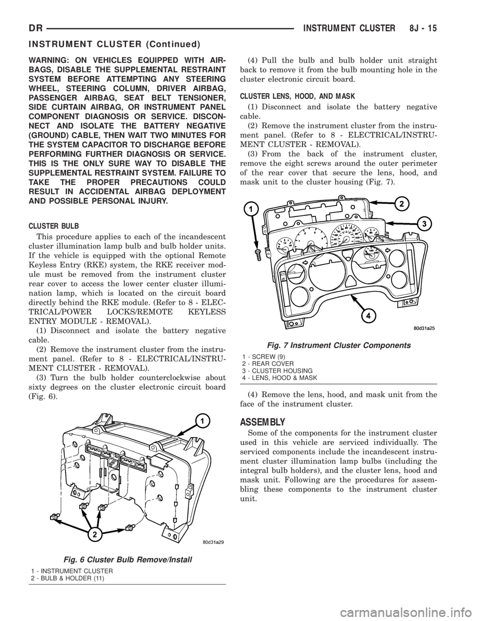
(3) Turn the bulb holder counterclockwise about
sixty degrees on the cluster electronic circuit board
(Fig. 6).(4) Pull the bulb and bulb holder unit straight
back to remove it from the bulb mounting hole in the
cluster electronic circuit board.
CLUSTER LENS, HOOD, AND MASK
(1) Disconnect and isolate the battery negative
cable.
(2) Remove the instrument cluster from the instru-
ment panel. (Refer to 8 - ELECTRICAL/INSTRU-
MENT CLUSTER - REMOVAL).
(3) From the back of the instrument cluster,
remove the eight screws around the outer perimeter
of the rear cover that secure the lens, hood, and
mask unit to the cluster housing (Fig. 7).
(4) Remove the lens, hood, and mask unit from the
face of the instrument cluster.
ASSEMBLY
Some of the components for the instrument cluster
used in this vehicle are serviced individually. The
serviced components include the incandescent instru-
ment cluster illumination lamp bulbs (including the
integral bulb holders), and the cluster lens, hood and
mask unit. Following are the procedures for assem-
bling these components to the instrument cluster
unit.
Fig. 6 Cluster Bulb Remove/Install
1 - INSTRUMENT CLUSTER
2 - BULB & HOLDER (11)
Fig. 7 Instrument Cluster Components
1 - SCREW (9)
2 - REAR COVER
3 - CLUSTER HOUSING
4 - LENS, HOOD & MASK
DRINSTRUMENT CLUSTER 8J - 15
INSTRUMENT CLUSTER (Continued)