2003 DODGE RAM Pcv valve
[x] Cancel search: Pcv valvePage 2841 of 2895

SPECIFICATIONS
TORQUE - EVAP SYSTEM
DESCRIPTION N´m Ft. Lbs. In. Lbs.
EVAP Canister Mounting
Nuts11 -95
EVAP Canister Mounting
Bracket-to-Frame Bolts14 10125
Leak Detection Pump
Mounting Bolts11 - 9 5
Leak Detection Pump
Filter Mounting Bolt11 - 9 5
CCV HOSE
DESCRIPTION - 8.0L V-10
The 8.0L V-10 engine is equipped with a Crankcase
Ventilation (CCV) system. The CCV system performs
the same function as a conventional PCV system, but
does not use a vacuum controlled valve (PCV valve).
A molded vacuum tube connects manifold vacuum
to the top of the right cylinder head (valve) cover.
The vacuum tube connects to a fixed orifice fitting
(Fig. 2) of a calibrated size 2.6 mm (0.10 inches).
OPERATION - 8.0L V-10
A molded vacuum tube connects manifold vacuum
to the top of the right cylinder head (valve) cover.
The vacuum tube connects to a fixed orifice fitting
(Fig. 2) of a calibrated size 2.6 mm (0.10 inches). Thefitting meters the amount of crankcase vapors drawn
out of the engine.The fixed orifice fitting is grey
in color.A similar fitting (but does not contain a
fixed orifice) is used on the left cylinder head (valve)
cover. This fitting is black in color. Do not inter-
change these two fittings.
When the engine is operating, fresh air enters the
engine and mixes with crankcase vapors. Manifold
vacuum draws the vapor/air mixture through the
fixed orifice and into the intake manifold. The vapors
are then consumed during engine combustion.
EVAP/PURGE SOLENOID
DESCRIPTION
The duty cycle EVAP canister purge solenoid is
located in the engine compartment. It is attached to
the side of the Power Distribution Center (PDC).
OPERATION
The Powertrain Control Module (PCM) operates
the solenoid.
During the cold start warm-up period and the hot
start time delay, the PCM does not energize the sole-
noid. When de-energized, no vapors are purged. The
PCM de-energizes the solenoid during open loop oper-
ation.
The engine enters closed loop operation after it
reaches a specified temperature and the time delay
ends. During closed loop operation, the PCM ener-
gizes and de-energizes the solenoid 5 or 10 times per
second, depending upon operating conditions. The
PCM varies the vapor flow rate by changing solenoid
pulse width. Pulse width is the amount of time the
solenoid energizes. The PCM adjusts solenoid pulse
width based on engine operating condition.
Fig. 2 FIXED ORIFICE FITTING - 8.0L V-10 ENGINE -
TYPICAL
1 - VACUUM TUBE
2 - FIXED ORIFICE FITTING
3 - COIL PACKS
4 - ORIFICE FITTING HOSE CONNECTIONS
25 - 12 EVAPORATIVE EMISSIONSDR
EVAPORATIVE EMISSIONS (Continued)
Page 2845 of 2895
REMOVAL
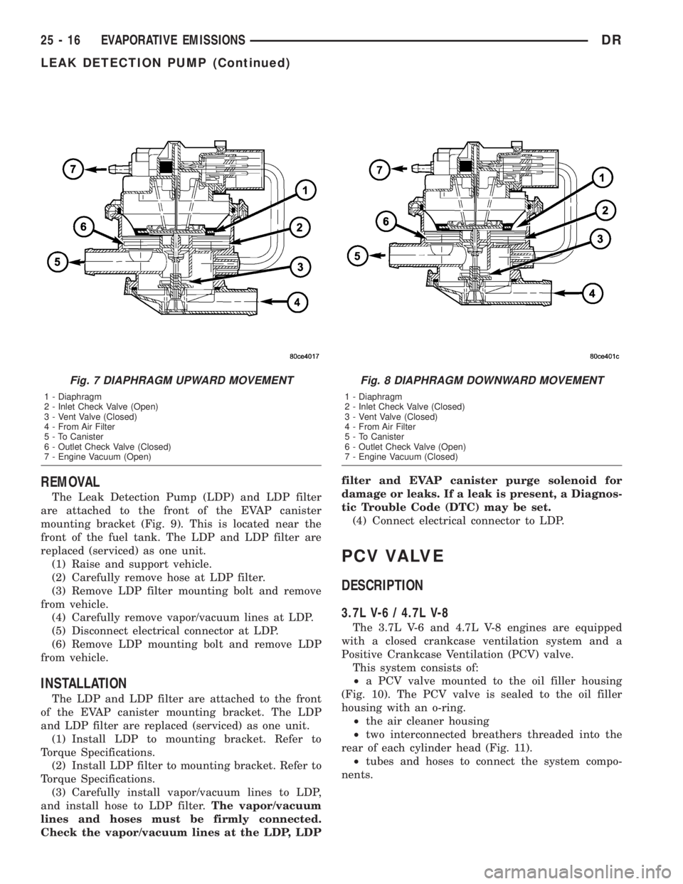
The Leak Detection Pump (LDP) and LDP filter
are attached to the front of the EVAP canister
mounting bracket (Fig. 9). This is located near the
front of the fuel tank. The LDP and LDP filter are
replaced (serviced) as one unit.
(1) Raise and support vehicle.
(2) Carefully remove hose at LDP filter.
(3) Remove LDP filter mounting bolt and remove
from vehicle.
(4) Carefully remove vapor/vacuum lines at LDP.
(5) Disconnect electrical connector at LDP.
(6) Remove LDP mounting bolt and remove LDP
from vehicle.
INSTALLATION
The LDP and LDP filter are attached to the front
of the EVAP canister mounting bracket. The LDP
and LDP filter are replaced (serviced) as one unit.
(1) Install LDP to mounting bracket. Refer to
Torque Specifications.
(2) Install LDP filter to mounting bracket. Refer to
Torque Specifications.
(3) Carefully install vapor/vacuum lines to LDP,
and install hose to LDP filter.The vapor/vacuum
lines and hoses must be firmly connected.
Check the vapor/vacuum lines at the LDP, LDPfilter and EVAP canister purge solenoid for
damage or leaks. If a leak is present, a Diagnos-
tic Trouble Code (DTC) may be set.
(4) Connect electrical connector to LDP.
PCV VALVE
DESCRIPTION
3.7L V-6 / 4.7L V-8
The 3.7L V-6 and 4.7L V-8 engines are equipped
with a closed crankcase ventilation system and a
Positive Crankcase Ventilation (PCV) valve.
This system consists of:
²a PCV valve mounted to the oil filler housing
(Fig. 10). The PCV valve is sealed to the oil filler
housing with an o-ring.
²the air cleaner housing
²two interconnected breathers threaded into the
rear of each cylinder head (Fig. 11).
²tubes and hoses to connect the system compo-
nents.
Fig. 7 DIAPHRAGM UPWARD MOVEMENT
1 - Diaphragm
2 - Inlet Check Valve (Open)
3 - Vent Valve (Closed)
4 - From Air Filter
5 - To Canister
6 - Outlet Check Valve (Closed)
7 - Engine Vacuum (Open)
Fig. 8 DIAPHRAGM DOWNWARD MOVEMENT
1 - Diaphragm
2 - Inlet Check Valve (Closed)
3 - Vent Valve (Closed)
4 - From Air Filter
5 - To Canister
6 - Outlet Check Valve (Open)
7 - Engine Vacuum (Closed)
25 - 16 EVAPORATIVE EMISSIONSDR
LEAK DETECTION PUMP (Continued)
Page 2846 of 2895
5.7L V-8
The 5.7L V-8 engine is equipped with a closed
crankcase ventilation system and a Positive Crank-
case Ventilation (PCV) valve.
This system consists of:
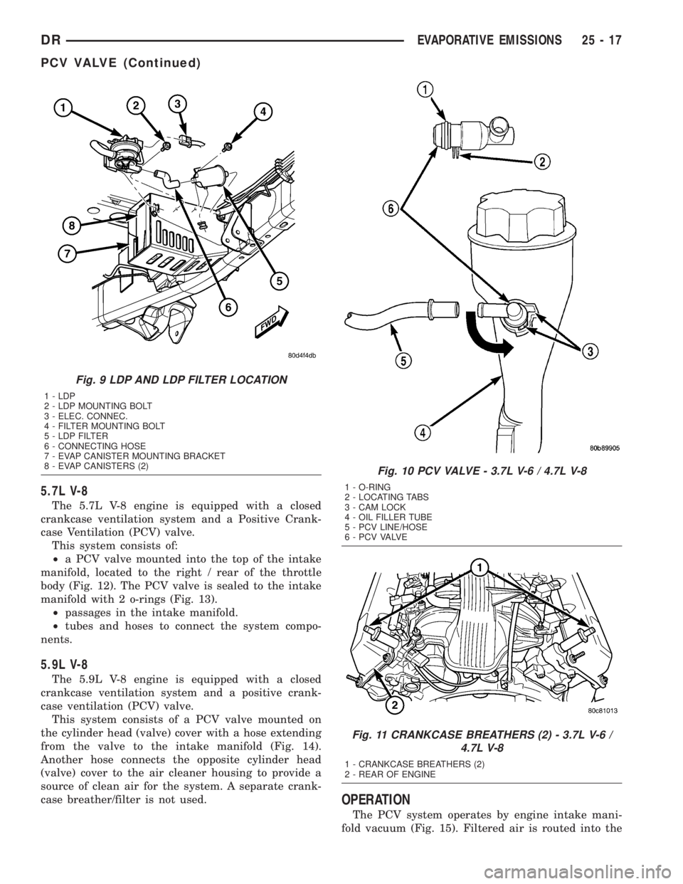
²a PCV valve mounted into the top of the intake
manifold, located to the right / rear of the throttle
body (Fig. 12). The PCV valve is sealed to the intake
manifold with 2 o-rings (Fig. 13).
²passages in the intake manifold.
²tubes and hoses to connect the system compo-
nents.
5.9L V-8
The 5.9L V-8 engine is equipped with a closed
crankcase ventilation system and a positive crank-
case ventilation (PCV) valve.
This system consists of a PCV valve mounted on
the cylinder head (valve) cover with a hose extending
from the valve to the intake manifold (Fig. 14).
Another hose connects the opposite cylinder head
(valve) cover to the air cleaner housing to provide a
source of clean air for the system. A separate crank-
case breather/filter is not used.
OPERATION
The PCV system operates by engine intake mani-
fold vacuum (Fig. 15). Filtered air is routed into the
Fig. 9 LDP AND LDP FILTER LOCATION
1 - LDP
2 - LDP MOUNTING BOLT
3 - ELEC. CONNEC.
4 - FILTER MOUNTING BOLT
5 - LDP FILTER
6 - CONNECTING HOSE
7 - EVAP CANISTER MOUNTING BRACKET
8 - EVAP CANISTERS (2)
Fig. 10 PCV VALVE - 3.7L V-6 / 4.7L V-8
1 - O-RING
2 - LOCATING TABS
3 - CAM LOCK
4 - OIL FILLER TUBE
5 - PCV LINE/HOSE
6 - P C V VA LV E
Fig. 11 CRANKCASE BREATHERS (2) - 3.7L V-6 /
4.7L V-8
1 - CRANKCASE BREATHERS (2)
2 - REAR OF ENGINE
DREVAPORATIVE EMISSIONS 25 - 17
PCV VALVE (Continued)
Page 2847 of 2895
crankcase through the air cleaner hose. The metered
air, along with crankcase vapors, are drawn through
the PCV valve and into a passage in the intake man-ifold. The PCV system manages crankcase pressure
and meters blow by gases to the intake system,
reducing engine sludge formation.
The PCV valve contains a spring loaded plunger.
This plunger meters the amount of crankcase vapors
routed into the combustion chamber based on intake
manifold vacuum.
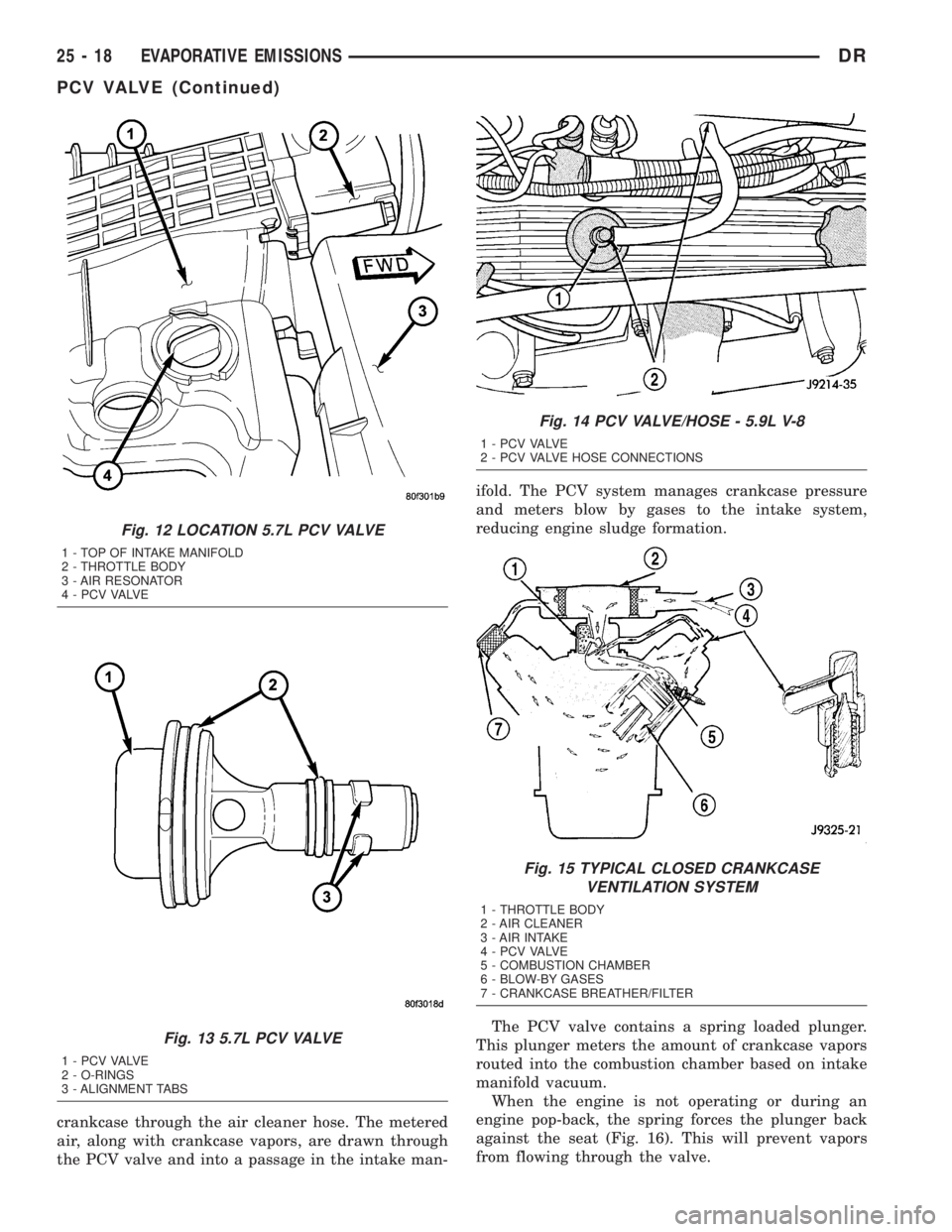
When the engine is not operating or during an
engine pop-back, the spring forces the plunger back
against the seat (Fig. 16). This will prevent vapors
from flowing through the valve.
Fig. 12 LOCATION 5.7L PCV VALVE
1 - TOP OF INTAKE MANIFOLD
2 - THROTTLE BODY
3 - AIR RESONATOR
4 - P C V VA LV E
Fig. 13 5.7L PCV VALVE
1 - P C V VA LV E
2 - O-RINGS
3 - ALIGNMENT TABS
Fig. 14 PCV VALVE/HOSE - 5.9L V-8
1 - P C V VA LV E
2 - PCV VALVE HOSE CONNECTIONS
Fig. 15 TYPICAL CLOSED CRANKCASE
VENTILATION SYSTEM
1 - THROTTLE BODY
2 - AIR CLEANER
3 - AIR INTAKE
4 - P C V VA LV E
5 - COMBUSTION CHAMBER
6 - BLOW-BY GASES
7 - CRANKCASE BREATHER/FILTER
25 - 18 EVAPORATIVE EMISSIONSDR
PCV VALVE (Continued)
Page 2848 of 2895
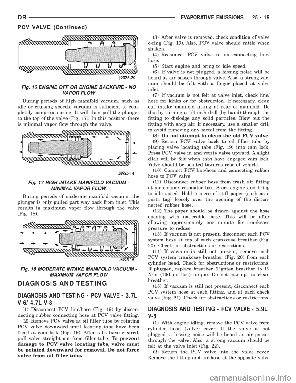
During periods of high manifold vacuum, such as
idle or cruising speeds, vacuum is sufficient to com-
pletely compress spring. It will then pull the plunger
to the top of the valve (Fig. 17). In this position there
is minimal vapor flow through the valve.
During periods of moderate manifold vacuum, the
plunger is only pulled part way back from inlet. This
results in maximum vapor flow through the valve
(Fig. 18).
DIAGNOSIS AND TESTING
DIAGNOSIS AND TESTING - PCV VALVE - 3.7L
V-6/ 4.7L V-8
(1) Disconnect PCV line/hose (Fig. 19) by discon-
necting rubber connecting hose at PCV valve fitting.
(2) Remove PCV valve at oil filler tube by rotating
PCV valve downward until locating tabs have been
freed at cam lock (Fig. 19). After tabs have cleared,
pull valve straight out from filler tube.To prevent
damage to PCV valve locating tabs, valve must
be pointed downward for removal. Do not force
valve from oil filler tube.(3) After valve is removed, check condition of valve
o-ring (Fig. 19). Also, PCV valve should rattle when
shaken.
(4) Reconnect PCV valve to its connecting line/
hose.
(5) Start engine and bring to idle speed.
(6) If valve is not plugged, a hissing noise will be
heard as air passes through valve. Also, a strong vac-
uum should be felt with a finger placed at valve
inlet.
(7) If vacuum is not felt at valve inlet, check line/
hose for kinks or for obstruction. If necessary, clean
out intake manifold fitting at rear of manifold. Do
this by turning a 1/4 inch drill (by hand) through the
fitting to dislodge any solid particles. Blow out the
fitting with shop air. If necessary, use a smaller drill
to avoid removing any metal from the fitting.
(8)Do not attempt to clean the old PCV valve.
(9) Return PCV valve back to oil filler tube by
placing valve locating tabs (Fig. 19) into cam lock.
Press PCV valve in and rotate valve upward. A slight
click will be felt when tabs have engaged cam lock.
Valve should be pointed towards rear of vehicle.
(10) Connect PCV line/hose and connecting rubber
hose to PCV valve.
(11) Disconnect rubber hose from fresh air fitting
at air cleaner resonator box. Start engine and bring
to idle speed. Hold a piece of stiff paper (such as a
parts tag) loosely over the opening of the discon-
nected rubber hose.
(12) The paper should be drawn against the hose
opening with noticeable force. This will be after
allowing approximately one minute for crankcase
pressure to reduce.
(13) If vacuum is not present, disconnect each PCV
system hose at top of each crankcase breather (Fig.
20). Check for obstructions or restrictions.
(14) If vacuum is still not present, remove each
PCV system crankcase breather (Fig. 20) from each
cylinder head. Check for obstructions or restrictions.
If plugged, replace breather. Tighten breather to 12
N´m (106 in. lbs.) torque. Do not attempt to clean
breather.
(15) If vacuum is still not present, disconnect each
PCV system hose at each fitting, and at each check
valve (Fig. 21). Check for obstructions or restrictions.DIAGNOSIS AND TESTING - PCV VALVE - 5.9L
V-8
(1) With engine idling, remove the PCV valve from
cylinder head (valve) cover. If the valve is not
plugged, a hissing noise will be heard as air passes
through the valve. Also, a strong vacuum should be
felt at the valve inlet (Fig. 22).
(2) Return the PCV valve into the valve cover.
Remove the fitting and air hose at the opposite valve
Fig. 16 ENGINE OFF OR ENGINE BACKFIRE - NO
VAPOR FLOW
Fig. 17 HIGH INTAKE MANIFOLD VACUUM -
MINIMAL VAPOR FLOW
Fig. 18 MODERATE INTAKE MANIFOLD VACUUM -
MAXIMUM VAPOR FLOW
DREVAPORATIVE EMISSIONS 25 - 19
PCV VALVE (Continued)
Page 2849 of 2895
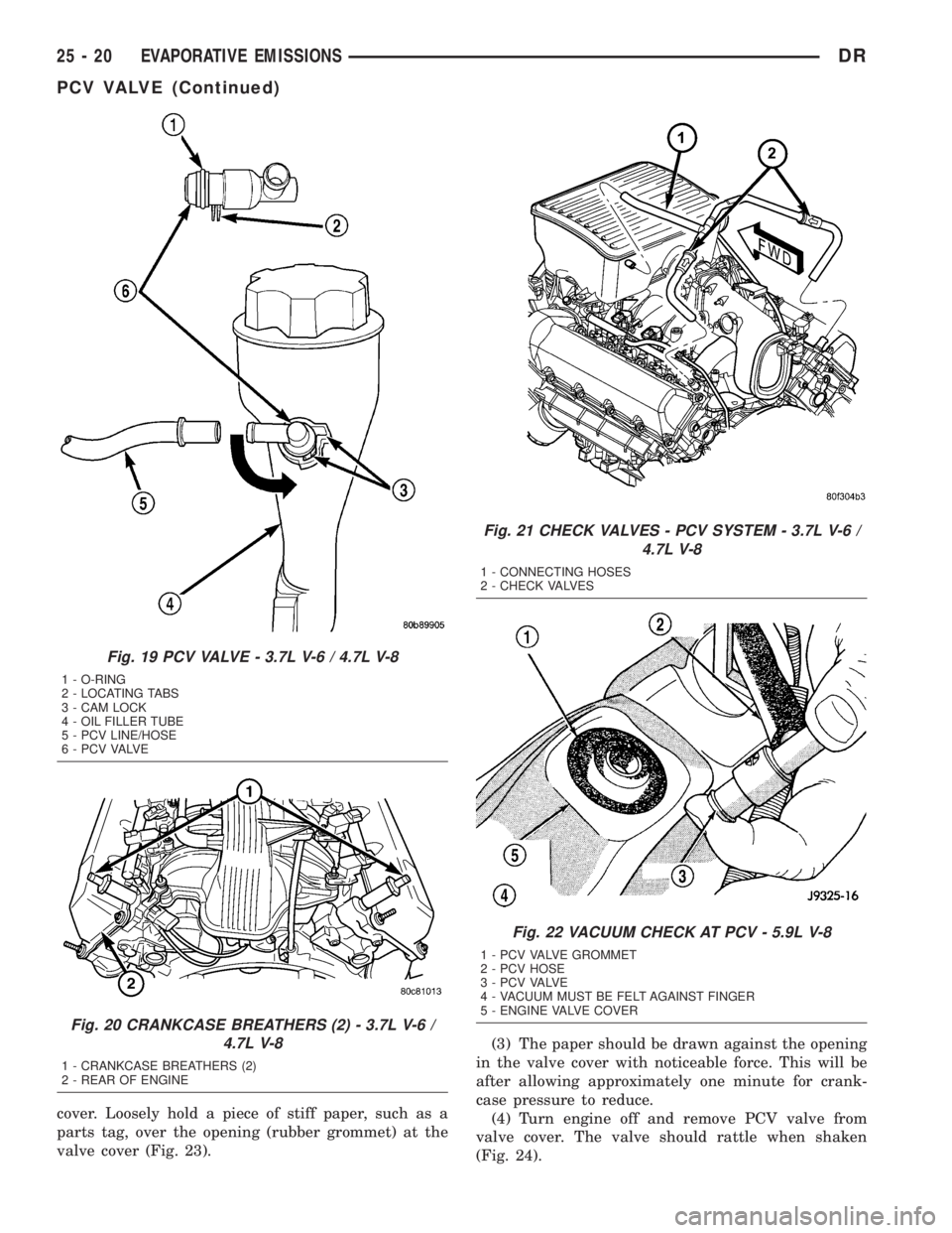
cover. Loosely hold a piece of stiff paper, such as a
parts tag, over the opening (rubber grommet) at the
valve cover (Fig. 23).(3) The paper should be drawn against the opening
in the valve cover with noticeable force. This will be
after allowing approximately one minute for crank-
case pressure to reduce.
(4) Turn engine off and remove PCV valve from
valve cover. The valve should rattle when shaken
(Fig. 24).
Fig. 19 PCV VALVE - 3.7L V-6 / 4.7L V-8
1 - O-RING
2 - LOCATING TABS
3 - CAM LOCK
4 - OIL FILLER TUBE
5 - PCV LINE/HOSE
6 - P C V VA LV E
Fig. 20 CRANKCASE BREATHERS (2) - 3.7L V-6 /
4.7L V-8
1 - CRANKCASE BREATHERS (2)
2 - REAR OF ENGINE
Fig. 21 CHECK VALVES - PCV SYSTEM - 3.7L V-6 /
4.7L V-8
1 - CONNECTING HOSES
2 - CHECK VALVES
Fig. 22 VACUUM CHECK AT PCV - 5.9L V-8
1 - PCV VALVE GROMMET
2 - PCV HOSE
3 - P C V VA LV E
4 - VACUUM MUST BE FELT AGAINST FINGER
5 - ENGINE VALVE COVER
25 - 20 EVAPORATIVE EMISSIONSDR
PCV VALVE (Continued)
Page 2850 of 2895
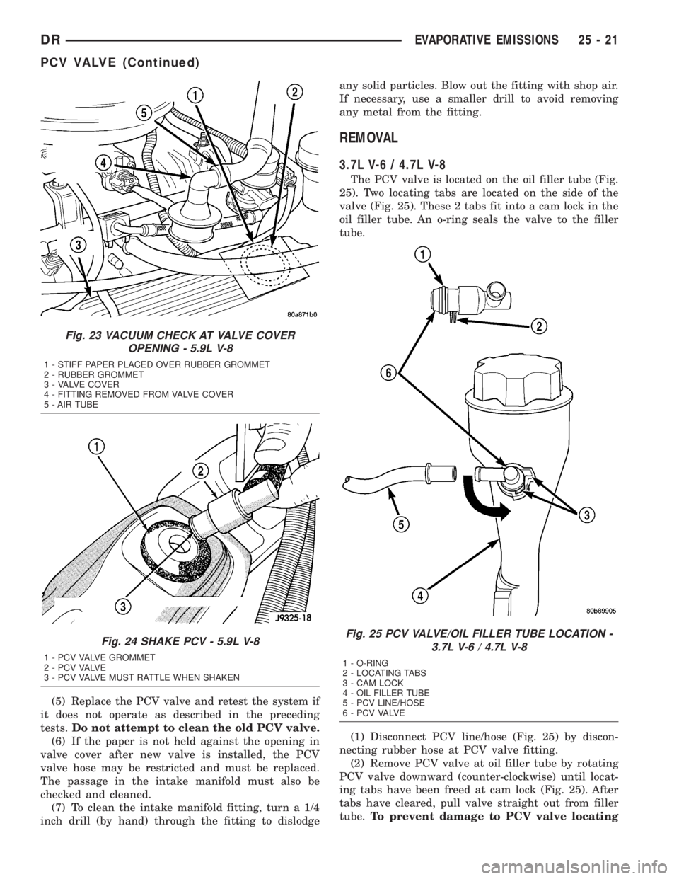
(5) Replace the PCV valve and retest the system if
it does not operate as described in the preceding
tests.Do not attempt to clean the old PCV valve.
(6) If the paper is not held against the opening in
valve cover after new valve is installed, the PCV
valve hose may be restricted and must be replaced.
The passage in the intake manifold must also be
checked and cleaned.
(7) To clean the intake manifold fitting, turn a 1/4
inch drill (by hand) through the fitting to dislodgeany solid particles. Blow out the fitting with shop air.
If necessary, use a smaller drill to avoid removing
any metal from the fitting.
REMOVAL
3.7L V-6 / 4.7L V-8
The PCV valve is located on the oil filler tube (Fig.
25). Two locating tabs are located on the side of the
valve (Fig. 25). These 2 tabs fit into a cam lock in the
oil filler tube. An o-ring seals the valve to the filler
tube.
(1) Disconnect PCV line/hose (Fig. 25) by discon-
necting rubber hose at PCV valve fitting.
(2) Remove PCV valve at oil filler tube by rotating
PCV valve downward (counter-clockwise) until locat-
ing tabs have been freed at cam lock (Fig. 25). After
tabs have cleared, pull valve straight out from filler
tube.To prevent damage to PCV valve locating
Fig. 23 VACUUM CHECK AT VALVE COVER
OPENING - 5.9L V-8
1 - STIFF PAPER PLACED OVER RUBBER GROMMET
2 - RUBBER GROMMET
3 - VALVE COVER
4 - FITTING REMOVED FROM VALVE COVER
5 - AIR TUBE
Fig. 24 SHAKE PCV - 5.9L V-8
1 - PCV VALVE GROMMET
2 - P C V VA LV E
3 - PCV VALVE MUST RATTLE WHEN SHAKEN
Fig. 25 PCV VALVE/OIL FILLER TUBE LOCATION -
3.7L V-6 / 4.7L V-8
1 - O-RING
2 - LOCATING TABS
3 - CAM LOCK
4 - OIL FILLER TUBE
5 - PCV LINE/HOSE
6 - P C V VA LV E
DREVAPORATIVE EMISSIONS 25 - 21
PCV VALVE (Continued)
Page 2851 of 2895

tabs, valve must be pointed downward for
removal. Do not force valve from oil filler tube.
(3) After valve is removed, check condition of valve
o-ring (Fig. 25).
5.7L V-8
The PCV valve is mounted into the top of the
intake manifold, located to the right / rear of the
throttle body (Fig. 12). The PCV valve is sealed to
the intake manifold with 2 o-rings (Fig. 13).
(1) Remove PCV valve by rotating counter-clock-
wise 90 degrees until locating tabs have been freed.
After tabs have cleared, pull valve straight up from
intake manifold.
(2) After valve is removed, check condition of 2
valve o-rings.
INSTALLATION
3.7L V6 / 4.7L V-8
The PCV valve is located on the oil filler tube. Two
locating tabs are located on the side of the valve.
These 2 tabs fit into a cam lock in the oil filler tube.
An o-ring seals the valve to the filler tube.
(1) Return PCV valve back to oil filler tube by
placing valve locating tabs into cam lock. Press PCV
valve in and rotate valve upward. A slight click will
be felt when tabs have engaged cam lock. Valve
should be pointed towards rear of vehicle.
(2) Connect PCV line/hose and rubber hose to PCV
valve.
5.7L V-8
(1) Clean out intake manifold opening.
(2) Check condition of 2 o-rings on PCV valve.
(3) Apply engine oil to 2 o-rings.
(4) Place PCV valve into intake manifold and
rotate 90 degrees clockwise for installation.
VACUUM LINES
DESCRIPTION
A vacuum schematic for emission related items can
be found on the vehicles VECI label. Refer to Vehicle
Emission Control Information (VECI) Label for label
location.
VAPOR CANISTER
DESCRIPTION
Two, maintenance free, EVAP canisters are used.
Both canisters are mounted into a two-piece support
bracket located near the front of the fuel tank (Fig.
26).
OPERATION
Two, maintenance free, EVAP canisters are
used.The EVAP canisters are filled with granules of
an activated carbon mixture. Fuel vapors entering
the EVAP canisters are absorbed by the charcoal
granules.
Fuel tank pressure vents into the EVAP canisters.
Fuel vapors are temporarily held in the canisters
until they can be drawn into the intake manifold.
The duty cycle EVAP canister purge solenoid allows
the EVAP canisters to be purged at predetermined
times and at certain engine operating conditions.
REMOVAL
Two, maintenance free, EVAP canisters are used.
Both canisters are mounted into a two-piece support
bracket located near the front of the fuel tank (Fig.
26).
(1) Raise and support vehicle.
(2) Remove fuel tubes/lines at each EVAP canister.
Note location of tubes/lines before removal for easier
installation.
(3) Remove lower support bracket (Fig. 27).
(4) Remove mounting nuts at top of each canister
(Fig. 27).
Fig. 26 LOCATION, EVAP CANISTERS
1 - LDP
2 - LDP MOUNTING BOLT
3 - ELEC. CONNEC.
4 - FILTER MOUNTING BOLT
5 - LDP FILTER
6 - CONNECTING HOSE
7 - EVAP CANISTER MOUNTING BRACKET
8 - EVAP CANISTERS (2)
25 - 22 EVAPORATIVE EMISSIONSDR
PCV VALVE (Continued)