2003 DODGE RAM Engine system
[x] Cancel search: Engine systemPage 808 of 2895
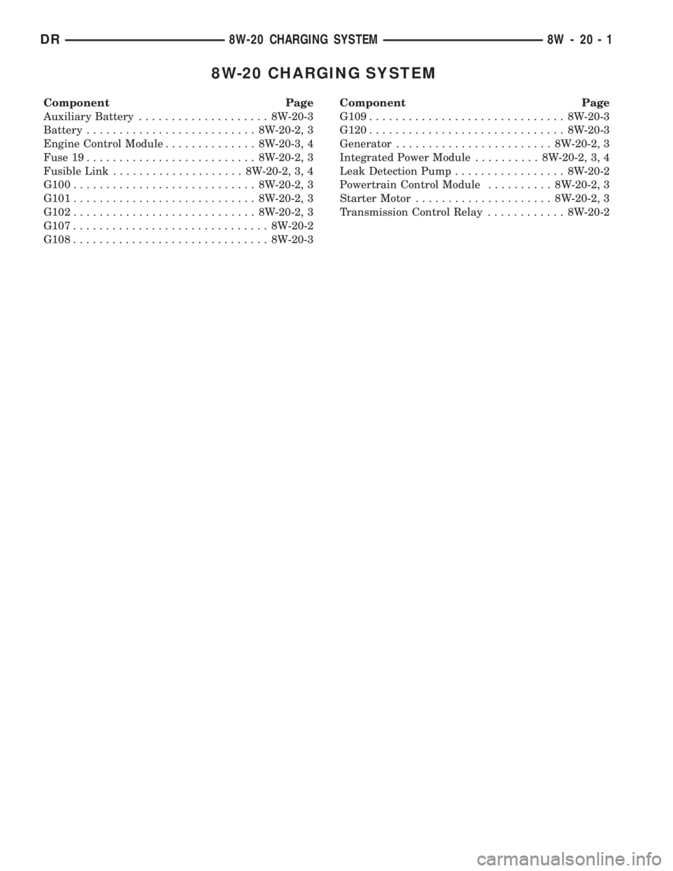
8W-20 CHARGING SYSTEM
Component Page
Auxiliary Battery.................... 8W-20-3
Battery.......................... 8W-20-2, 3
Engine Control Module.............. 8W-20-3, 4
Fuse 19.......................... 8W-20-2, 3
Fusible Link.................... 8W-20-2, 3, 4
G100............................ 8W-20-2, 3
G101............................ 8W-20-2, 3
G102............................ 8W-20-2, 3
G107.............................. 8W-20-2
G108.............................. 8W-20-3Component Page
G109.............................. 8W-20-3
G120.............................. 8W-20-3
Generator........................ 8W-20-2, 3
Integrated Power Module.......... 8W-20-2, 3, 4
Leak Detection Pump................. 8W-20-2
Powertrain Control Module.......... 8W-20-2, 3
Starter Motor..................... 8W-20-2, 3
Transmission Control Relay............ 8W-20-2
DR8W-20 CHARGING SYSTEM 8W - 20 - 1
Page 816 of 2895

8W-30 FUEL/IGNITION SYSTEM
Component PageA/C Compressor Clutch Relay...........8W-30-27, 36, 83
A/C Pressure Transducer.......8W-30-19, 20, 21, 48, 53, 70
Accelerator Pedal Position Sensor.............8W-30-55
Adjustable Pedal Motor....................8W-30-87
Adjustable Pedal Relay....................8W-30-87
Adjustable Pedal Switch...................8W-30-87
Ambient Temperature Sensor................8W-30-56
Auto Shut Down Relay..................8W-30-4, 31
Battery..............................8W-30-77
Battery Temperature Sensor............8W-30-28, 39, 81
Brake Lamp Switch.............8W-30-25, 35, 65, 82, 89
Camshaft Position Sensor.......8W-30-17, 18, 37, 55, 70, 71
Capacitor.........................8W-30-6, 11, 43
Clockspring..................8W-30-25, 35, 65, 84, 90
Clutch Interlock Brake Switch...............8W-30-32
Coil On Plug No. 1...................8W-30-8, 42, 61
Coil On Plug No. 2...................8W-30-7, 40, 60
Coil On Plug No. 3...................8W-30-8, 42, 61
Coil On Plug No. 4...................8W-30-7, 40, 60
Coil On Plug No. 5...................8W-30-6, 41, 61
Coil On Plug No. 6...................8W-30-6, 43, 60
Coil On Plug No. 7....................8W-30-41, 61
Coil On Plug No. 8....................8W-30-43, 60
Condenser Fan Relay...................8W-30-27, 36
Controller Antilock Brake...........8W-30-23, 33, 38, 82
Crankshaft Position Sensor.............8W-30-17, 18, 37
Data Link Connector..........8W-30-27, 36, 46, 80, 89, 91
Data Link Connector-Engine................8W-30-75
Electronic Throttle Control Module............8W-30-63
Engine Control Module......8W-30-67, 68, 69, 70, 71, 72, 73,
74, 75, 76, 77, 78, 79, 80, 81, 82,
83, 84, 90, 91
Engine Coolant Temperature
Sensor.................8W-30-19, 20, 21, 48, 64, 72
Engine Oil Pressure Switch......8W-30-19, 20, 21, 29, 78, 81
EVAP/Purge Solenoid...................8W-30-28, 39
Front Control Module.....................8W-30-87
Fuel Heater...........................8W-30-85
Fuel Heater Relay.......................8W-30-85
Fuel Injector No. 1...............8W-30-8, 9, 11, 42, 62
Fuel Injector No. 2...............8W-30-7, 9, 12, 40, 59
Fuel Injector No. 3...............8W-30-8, 9, 11, 42, 62
Fuel Injector No. 4...............8W-30-7, 9, 12, 40, 60
Fuel Injector No. 5...............8W-30-6, 9, 11, 41, 62
Fuel Injector No. 6...............8W-30-6, 9, 12, 43, 59
Fuel Injector No. 7................8W-30-9, 11, 41, 62
Fuel Injector No. 8................8W-30-9, 12, 43, 59
Fuel Injector No. 9.......................8W-30-11
Fuel Injector No. 10......................8W-30-12
Fuel Injector Pack No. 1...................8W-30-67
Fuel Injector Pack No. 2..............8W-30-67, 68, 69
Fuel Injector Pack No. 3...................8W-30-69
Fuel Pump Module................8W-30-3, 30, 79, 83
Fuel Pump Motor.......................8W-30-76
Fuel Pump Relay......................8W-30-3, 30
Fuel Rail Pressure Sensor..................8W-30-74
Fuse 2.............................8W-30-4, 31
Fuse 5............................8W-30-50, 88
Fuse 12.............................8W-30-85
Fuse 17............................8W-30-3, 30
Fuse 19.......................8W-30-2, 29, 77, 90
Fuse 36...........................8W-30-79, 87
Fuse 40.............................8W-30-87
Fuse 49............................8W-30-4, 31
Fuse 50...........................8W-30-28, 88Component PageFusible Link..........................8W-30-77
G103.........................8W-30-3, 25, 30, 35
G104.........................8W-30-3, 25, 30, 35
G105.............................8W-30-81, 86
G106...............................8W-30-85
G107.........8W-30-2, 16, 24, 29, 34, 40, 42, 45, 47, 50, 54
G114 ...............................8W-30-78
G117 ...............................8W-30-91
G120.............................8W-30-75, 85
G201..........................8W-30-23, 33, 91
G203...............................8W-30-87
Generator.......................8W-30-24, 34, 75
Idle Air Control Motor..................8W-30-27, 36
Ignition Coil...........................8W-30-9
Ignition Coil-Left.......................8W-30-10
Ignition Coil-Right.......................8W-30-10
Ignition Switch....................8W-30-23, 33, 46
Inlet Air Temperature/Pressure Sensor..........8W-30-73
Input Speed Sensor......................8W-30-49
Intake Air Heater Relay No. 1...............8W-30-81
Intake Air Heater Relay No. 2...............8W-30-81
Intake Air Temperature Sensor......8W-30-19, 20, 21, 48, 64
Intake Air Temperature/Manifold Absolute Pressure
Sensor............................8W-30-74
Integrated Power Module . . 8W-30-2, 3, 4, 26, 27, 29, 30, 31, 36,
50, 77, 79, 80, 83, 85, 86, 87, 88, 90
Knock Sensor..........................8W-30-22
Knock Sensor-Left.......................8W-30-57
Knock Sensor-Right......................8W-30-57
Leak Detection Pump..................8W-30-24, 34
Lift Pump Motor........................8W-30-75
Line Pressure Sensor.....................8W-30-44
Manifold Absolute Pressure
Sensor.................8W-30-19, 20, 21, 48, 55, 64
Output Speed Sensor................8W-30-26, 49, 88
Overdrive Switch...................8W-30-23, 33, 91
Oxygen Sensor 1/1 Upstream.......8W-30-13, 14, 15, 47, 54
Oxygen Sensor 1/2 Downstream.....8W-30-13, 14, 16, 45, 54
Oxygen Sensor 2/1 Upstream..............8W-30-15, 47
Oxygen Sensor 2/2 Downstream............8W-30-16, 45
Oxygen Sensor Downstream Relay...........8W-30-4, 31
Power Steering Pressure Switch............8W-30-24, 34
Powertrain Control Module . . 8W-30-2, 3, 4, 5, 6, 7, 8, 9, 10, 11,
12, 13, 14, 15, 16 17, 18, 19, 20, 21, 22, 23, 24, 25, 27, 28, 29,
30, 31, 32, 33, 34, 35, 36, 37, 38, 39, 40, 41, 42, 43, 44, 45, 46,
47, 48, 49, 50, 51, 52, 53, 54, 55, 56, 57, 58, 59, 60, 61, 62, 63,
64, 65, 66, 77, 79, 82, 84, 85, 88, 89, 90, 91
PTCNo.1 ...........8W-30-2, 3, 27, 29, 30, 36, 80, 83, 86
PTO Switch.........................8W-30-23, 33
Speed Control Servo.................8W-30-25, 35, 89
Speed Control Switch-Left.............8W-30-65, 84, 90
Speed Control Switch-Right............8W-30-65, 84, 90
Starter Motor Relay......................8W-30-29
Throttle Position Sensor.................8W-30-22, 44
Throttle Position Switch...................8W-30-72
Transfer Case Control Module...............8W-30-65
Transmission Control Module.......8W-30-17, 23, 33, 38, 66
Transmission Control Relay............8W-30-26, 50, 88
Transmission Range Sensor..................8W-30-5
Transmission Solenoid Assembly.......8W-30-20, 21, 26, 88
Transmission Solenoid/TRS Assembly . . 8W-30-5, 32, 50, 51, 52
Vacuum Pump.........................8W-30-86
Vehicle Speed Sensor.....................8W-30-71
Vistronic Fan Drive......................8W-30-79
Water In Fuel Sensor...................8W-30-72, 76
DR8W-30 FUEL/IGNITION SYSTEM 8W - 30 - 1
Page 908 of 2895

8W-31 TRANSMISSION CONTROL SYSTEM
Component Page
Automatic Day/Night Mirror........ 8W-31-7, 15
Brake Lamp Switch................. 8W-31-17
Clockspring........................ 8W-31-18
Clutch Interlock Brake Switch......... 8W-31-20
Data Link Connector....... 8W-31-5, 8, 17, 19, 25
Engine Control Module............ 8W-31-18, 19
Front Control Module.............. 8W-31-7, 10
Fuse 5.................... 8W-31-2, 10, 13, 16
Fuse 19........................... 8W-31-18
Fuse 28........................... 8W-31-23
Fuse 38...................... 8W-31-7, 10, 15
Fuse 43........................... 8W-31-20
Fuse 50........................... 8W-31-16
G107......................... 8W-31-2, 4, 10
G117............................. 8W-31-19
G201..................... 8W-31-9, 11, 19, 23
G203.......................... 8W-31-20, 25
Ignition Switch...................... 8W-31-5
Input Speed Sensor............... 8W-31-6, 14
Instrument Cluster............. 8W-31-5, 15, 23
Integrated Power Module . . . 8W-31-2, 7, 10, 13, 15,
16, 18, 20, 23
Line Pressure Sensor................. 8W-31-6
Output Speed Sensor........ 8W-31-6, 13, 14, 16Component Page
Overdrive Switch.............. 8W-31-9, 11, 19
Powertrain Control
Module . . 8W-31-3, 5, 8, 9, 10, 11, 12, 13, 14, 15,
16, 17, 18, 19
Speed Control Servo................. 8W-31-17
Speed Control Switch-Left............ 8W-31-18
Speed Control Switch-Right........... 8W-31-18
Starter Motor Relay................. 8W-31-20
Tail/Stop/Turn Signal Lamp-Left........ 8W-31-7
Tail/Stop/Turn Signal Lamp-Right....... 8W-31-7
Throttle Position Sensor............... 8W-31-9
Transfer Case Control
Module........... 8W-31-20, 21, 22, 23, 24, 25
Transfer Case Mode Sensor........ 8W-31-21, 22
Transfer Case Selector Switch...... 8W-31-23, 24
Transfer Case Shift Motor............ 8W-31-25
Transmission Control
Module.............. 8W-31-2, 3, 4, 5, 6, 8, 9
Transmission Control Relay . . . 8W-31-2, 10, 13, 16
Transmission Range Sensor........... 8W-31-15
Transmission Solenoid Assembly.... 8W-31-13, 16
Transmission Solenoid/TRS
Assembly........ 8W-31-2, 3, 4, 6, 7, 10, 11, 12
DR8W-31 TRANSMISSION CONTROL SYSTEM 8W - 31 - 1
Page 1244 of 2895
tery and provides the primary means of circuit pro-
tection and power distribution for all vehicle
electrical systems. The front control module controls
power to some of these vehicle systems electrical and
electromechanical loads based on inputs received
from hard wired switch inputs and data received on
the PCI bus circuit (J1850).
For information on theIntegrated Power Mod-
ule Refer to the Power Distribution Sectionof
the service manual.
OPERATION
As messages are sent over the PCI bus circuit, the
front control module reads these messages and con-
trols power to some of the vehicles electrical systems
by completing the circuit to ground (low side driver)
or completing the circuit to 12 volt power (high side
driver). The following functions areControlledby
the Front Control Module:
²Headlamp Power with Voltage Regulation
²Windshield Wiper ªON/OFFº Relay Actuation
²Windshield Wiper ªHI/LOº Relay Actuation
²Windshield Washer Pump Motor
²Fog Lamp Relay Actuation
²Park Lamp Relay Actuation
²Horn Relay Actuation
The following inputs areReceived/Monitoredby
the Front Control Module:
²B+ Connection Detection²Power Ground
²Ambient Temperature Sensing
²Ignition Switch Run
²Washer Fluid Level Switch
²Windshield Wiper Park Switch
²PCI Bus Circuit
DIAGNOSIS AND TESTING - FRONT CONTROL
MODULE
The front control module is a printed circuit board
based module with a on-board micro-processor. The
front control module interfaces with other electronic
modules in the vehicle via the Programmable Com-
munications Interface (PCI) data bus (J1850). In
order to obtain conclusive testing the Programmable
Communications Interface (PCI) data bus network
and all of the electronic modules that provide inputs
to, or receive outputs from the front control module
must be checked. All PCI (J1850) communication
faults must be resolved prior to further diagnosing
any front control module related issues.
The front control module was designed to be diag-
nosed with an appropriate diagnostic scan tool, such
as the DRB IIIt. The most reliable, efficient, and
accurate means to diagnose the front control module
requires the use of a DRB IIItscan tool and the
proper Body Diagnostic Procedures manual.
Before any testing of the front control module is
attempted, the battery should be fully charged and
all wire harness and ground connections inspected
around the affected areas on the vehicle.
REMOVAL
(1) Disconnect the positive and negative battery
cables from the battery.
(2) Partially remove the integrated power module
from the engine compartment (Refer to 8 - ELECTRI-
CAL/POWER DISTRIBUTION/INTEGRATED
POWER MODULE - REMOVAL).
(3)
Remove the front control module retaining
screws.
(4) Using both hands, pull the front control module
straightfrom the integrated power module assembly
to disconnect the 49-way electrical connector and
remove the front control module from the vehicle.
INSTALLATION
(1) Install the front control module on the inte-
grated power module assembly by pushing the
49-way electrical connector straight in.
(2) Install the front control module retaining
screws. Torque the screws to 7 in. lbs.
(3) Install the integrated power module (Refer to 8
- ELECTRICAL/POWER DISTRIBUTION/INTE-
GRATED POWER MODULE - INSTALLATION).
(4)
Connect the positive and negative battery cables.
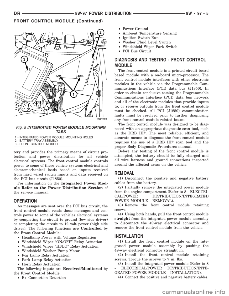
Fig. 5 INTEGRATED POWER MODULE MOUNTING
TABS
1 - INTEGRATED POWER MODULE MOUNTING HOLES
2 - BATTERY TRAY ASSEMBLY
3 - FRONT CONTROL MODULE
DR8W-97 POWER DISTRIBUTION 8W - 97 - 5
FRONT CONTROL MODULE (Continued)
Page 1253 of 2895
DIAGNOSIS AND TESTING
DIAGNOSIS AND TESTING - ENGINE
DIAGNOSIS - INTRODUCTION
Engine diagnosis is helpful in determining the
causes of malfunctions not detected and remedied by
routine maintenance.
These malfunctions may be classified as either per-
formance (e.g., engine idles rough and stalls) or
mechanical (e.g., a strange noise).
(Refer to 9 - ENGINE - DIAGNOSIS AND TEST-
ING)ÐPERFORMANCE and (Refer to 9 - ENGINE -
DIAGNOSIS AND TESTING)ÐMECHANICAL for
possible causes and corrections of malfunctions.
(Refer to 14 - FUEL SYSTEM/FUEL DELIVERY -
DIAGNOSIS AND TESTING) and (Refer to 14 -
FUEL SYSTEM/FUEL INJECTION - DIAGNOSIS
AND TESTING) for the fuel system diagnosis.Additional tests and diagnostic procedures may be
necessary for specific engine malfunctions that can
not be isolated with the Service Diagnosis charts.
Information concerning additional tests and diagno-
sis is provided within the following diagnosis:
²Cylinder Compression Pressure Test (Refer to 9 -
ENGINE - DIAGNOSIS AND TESTING).
²Cylinder Combustion Pressure Leakage Test
(Refer to 9 - ENGINE - DIAGNOSIS AND TEST-
ING).
²Engine Cylinder Head Gasket Failure Diagnosis
(Refer to 9 - ENGINE/CYLINDER HEAD - DIAGNO-
SIS AND TESTING).
²Intake Manifold Leakage Diagnosis (Refer to 9 -
ENGINE/MANIFOLDS/INTAKE MANIFOLD -
DIAGNOSIS AND TESTING).
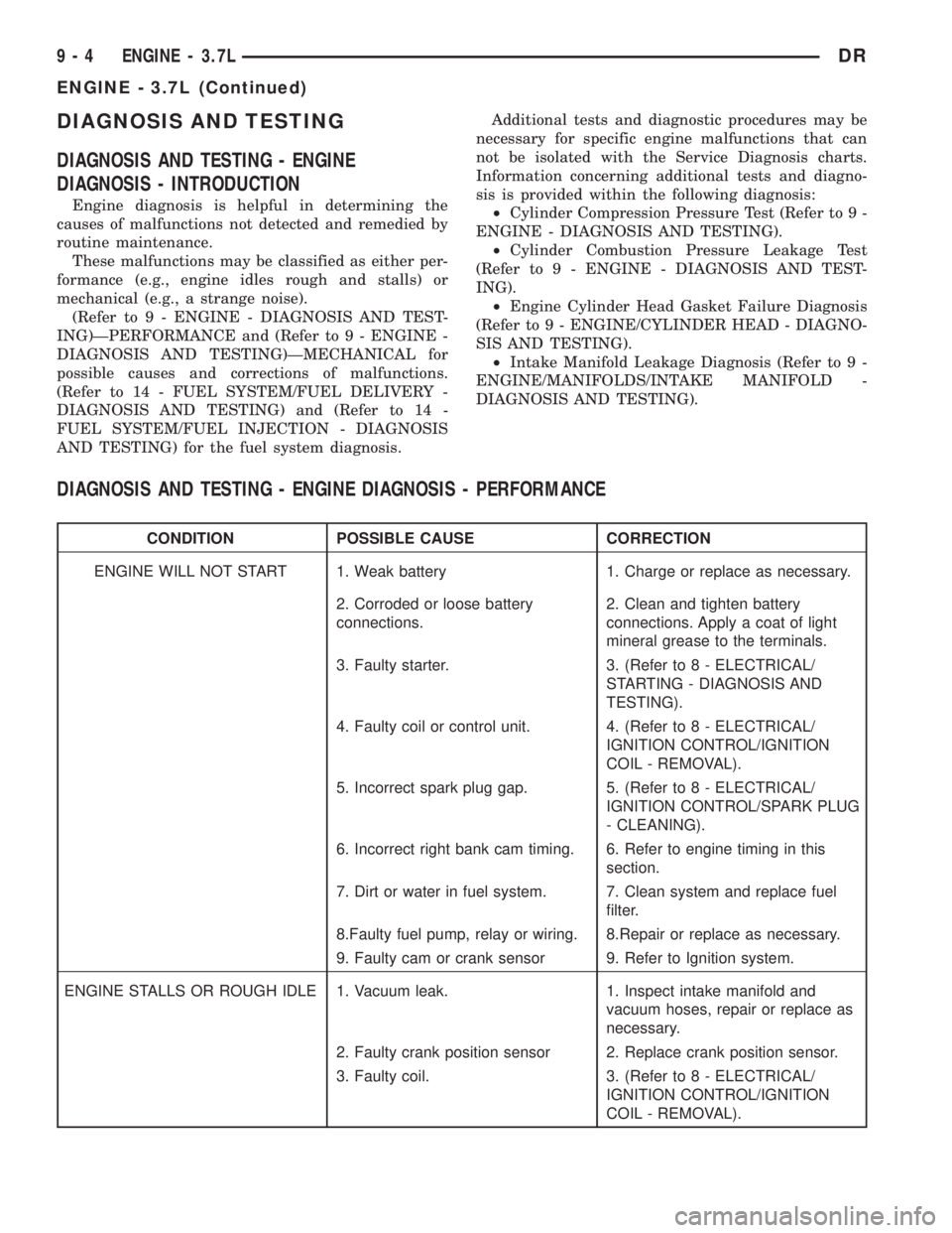
DIAGNOSIS AND TESTING - ENGINE DIAGNOSIS - PERFORMANCE
CONDITION POSSIBLE CAUSE CORRECTION
ENGINE WILL NOT START 1. Weak battery 1. Charge or replace as necessary.
2. Corroded or loose battery
connections.2. Clean and tighten battery
connections. Apply a coat of light
mineral grease to the terminals.
3. Faulty starter. 3. (Refer to 8 - ELECTRICAL/
STARTING - DIAGNOSIS AND
TESTING).
4. Faulty coil or control unit. 4. (Refer to 8 - ELECTRICAL/
IGNITION CONTROL/IGNITION
COIL - REMOVAL).
5. Incorrect spark plug gap. 5. (Refer to 8 - ELECTRICAL/
IGNITION CONTROL/SPARK PLUG
- CLEANING).
6. Incorrect right bank cam timing. 6. Refer to engine timing in this
section.
7. Dirt or water in fuel system. 7. Clean system and replace fuel
filter.
8.Faulty fuel pump, relay or wiring. 8.Repair or replace as necessary.
9. Faulty cam or crank sensor 9. Refer to Ignition system.
ENGINE STALLS OR ROUGH IDLE 1. Vacuum leak. 1. Inspect intake manifold and
vacuum hoses, repair or replace as
necessary.
2. Faulty crank position sensor 2. Replace crank position sensor.
3. Faulty coil. 3. (Refer to 8 - ELECTRICAL/
IGNITION CONTROL/IGNITION
COIL - REMOVAL).
9 - 4 ENGINE - 3.7LDR
ENGINE - 3.7L (Continued)
Page 1254 of 2895
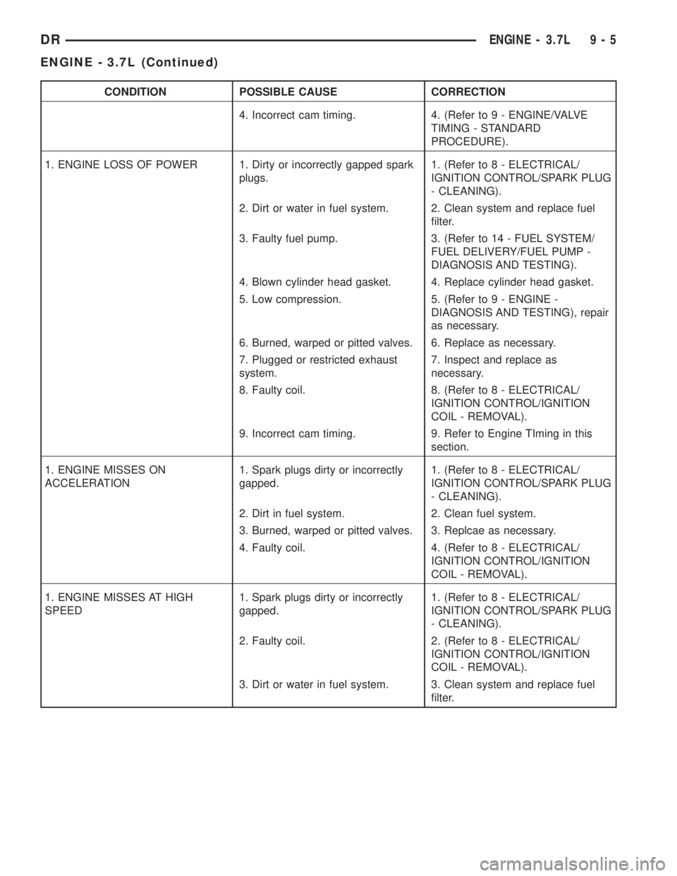
CONDITION POSSIBLE CAUSE CORRECTION
4. Incorrect cam timing. 4. (Refer to 9 - ENGINE/VALVE
TIMING - STANDARD
PROCEDURE).
1. ENGINE LOSS OF POWER 1. Dirty or incorrectly gapped spark
plugs.1. (Refer to 8 - ELECTRICAL/
IGNITION CONTROL/SPARK PLUG
- CLEANING).
2. Dirt or water in fuel system. 2. Clean system and replace fuel
filter.
3. Faulty fuel pump. 3. (Refer to 14 - FUEL SYSTEM/
FUEL DELIVERY/FUEL PUMP -
DIAGNOSIS AND TESTING).
4. Blown cylinder head gasket. 4. Replace cylinder head gasket.
5. Low compression. 5. (Refer to 9 - ENGINE -
DIAGNOSIS AND TESTING), repair
as necessary.
6. Burned, warped or pitted valves. 6. Replace as necessary.
7. Plugged or restricted exhaust
system.7. Inspect and replace as
necessary.
8. Faulty coil. 8. (Refer to 8 - ELECTRICAL/
IGNITION CONTROL/IGNITION
COIL - REMOVAL).
9. Incorrect cam timing. 9. Refer to Engine TIming in this
section.
1. ENGINE MISSES ON
ACCELERATION1. Spark plugs dirty or incorrectly
gapped.1. (Refer to 8 - ELECTRICAL/
IGNITION CONTROL/SPARK PLUG
- CLEANING).
2. Dirt in fuel system. 2. Clean fuel system.
3. Burned, warped or pitted valves. 3. Replcae as necessary.
4. Faulty coil. 4. (Refer to 8 - ELECTRICAL/
IGNITION CONTROL/IGNITION
COIL - REMOVAL).
1. ENGINE MISSES AT HIGH
SPEED1. Spark plugs dirty or incorrectly
gapped.1. (Refer to 8 - ELECTRICAL/
IGNITION CONTROL/SPARK PLUG
- CLEANING).
2. Faulty coil. 2. (Refer to 8 - ELECTRICAL/
IGNITION CONTROL/IGNITION
COIL - REMOVAL).
3. Dirt or water in fuel system. 3. Clean system and replace fuel
filter.
DRENGINE - 3.7L 9 - 5
ENGINE - 3.7L (Continued)
Page 1257 of 2895
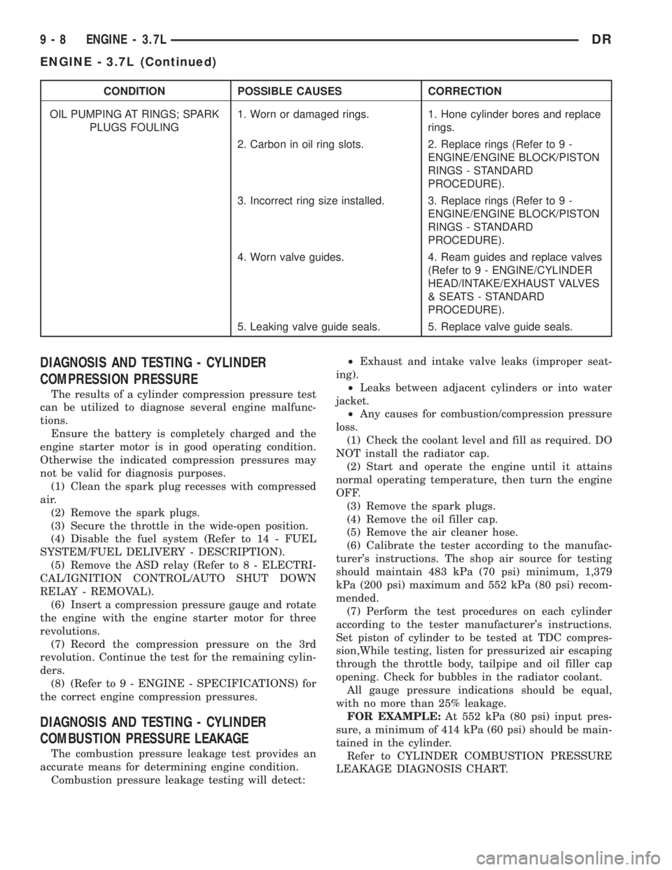
CONDITION POSSIBLE CAUSES CORRECTION
OIL PUMPING AT RINGS; SPARK
PLUGS FOULING1. Worn or damaged rings. 1. Hone cylinder bores and replace
rings.
2. Carbon in oil ring slots. 2. Replace rings (Refer to 9 -
ENGINE/ENGINE BLOCK/PISTON
RINGS - STANDARD
PROCEDURE).
3. Incorrect ring size installed. 3. Replace rings (Refer to 9 -
ENGINE/ENGINE BLOCK/PISTON
RINGS - STANDARD
PROCEDURE).
4. Worn valve guides. 4. Ream guides and replace valves
(Refer to 9 - ENGINE/CYLINDER
HEAD/INTAKE/EXHAUST VALVES
& SEATS - STANDARD
PROCEDURE).
5. Leaking valve guide seals. 5. Replace valve guide seals.
DIAGNOSIS AND TESTING - CYLINDER
COMPRESSION PRESSURE
The results of a cylinder compression pressure test
can be utilized to diagnose several engine malfunc-
tions.
Ensure the battery is completely charged and the
engine starter motor is in good operating condition.
Otherwise the indicated compression pressures may
not be valid for diagnosis purposes.
(1) Clean the spark plug recesses with compressed
air.
(2) Remove the spark plugs.
(3) Secure the throttle in the wide-open position.
(4) Disable the fuel system (Refer to 14 - FUEL
SYSTEM/FUEL DELIVERY - DESCRIPTION).
(5) Remove the ASD relay (Refer to 8 - ELECTRI-
CAL/IGNITION CONTROL/AUTO SHUT DOWN
RELAY - REMOVAL).
(6) Insert a compression pressure gauge and rotate
the engine with the engine starter motor for three
revolutions.
(7) Record the compression pressure on the 3rd
revolution. Continue the test for the remaining cylin-
ders.
(8) (Refer to 9 - ENGINE - SPECIFICATIONS) for
the correct engine compression pressures.
DIAGNOSIS AND TESTING - CYLINDER
COMBUSTION PRESSURE LEAKAGE
The combustion pressure leakage test provides an
accurate means for determining engine condition.
Combustion pressure leakage testing will detect:²Exhaust and intake valve leaks (improper seat-
ing).
²Leaks between adjacent cylinders or into water
jacket.
²Any causes for combustion/compression pressure
loss.
(1) Check the coolant level and fill as required. DO
NOT install the radiator cap.
(2) Start and operate the engine until it attains
normal operating temperature, then turn the engine
OFF.
(3) Remove the spark plugs.
(4) Remove the oil filler cap.
(5) Remove the air cleaner hose.
(6) Calibrate the tester according to the manufac-
turer's instructions. The shop air source for testing
should maintain 483 kPa (70 psi) minimum, 1,379
kPa (200 psi) maximum and 552 kPa (80 psi) recom-
mended.
(7) Perform the test procedures on each cylinder
according to the tester manufacturer's instructions.
Set piston of cylinder to be tested at TDC compres-
sion,While testing, listen for pressurized air escaping
through the throttle body, tailpipe and oil filler cap
opening. Check for bubbles in the radiator coolant.
All gauge pressure indications should be equal,
with no more than 25% leakage.
FOR EXAMPLE:At 552 kPa (80 psi) input pres-
sure, a minimum of 414 kPa (60 psi) should be main-
tained in the cylinder.
Refer to CYLINDER COMBUSTION PRESSURE
LEAKAGE DIAGNOSIS CHART.
9 - 8 ENGINE - 3.7LDR
ENGINE - 3.7L (Continued)
Page 1259 of 2895
of oil and coolant. Can be used on threaded and
machined parts under all temperatures. This mate-
rial is used on engines with multi-layer steel (MLS)
cylinder head gaskets. This material also will pre-
vent corrosion. MopartGasket Sealant is available in
a 13 oz. aerosol can or 4oz./16 oz. can w/applicator.
FORM-IN-PLACE GASKET AND SEALER
APPLICATION
Assembling parts using a form-in-place gasket
requires care but it's easier than using precut gas-
kets.
MopartGasket Maker material should be applied
sparingly 1 mm (0.040 in.) diameter or less of sealant
to one gasket surface. Be certain the material sur-
rounds each mounting hole. Excess material can eas-
ily be wiped off. Components should be torqued in
place within 15 minutes. The use of a locating dowel
is recommended during assembly to prevent smear-
ing material off the location.
MopartEngine RTV GEN II or ATF RTV gasket
material should be applied in a continuous bead
approximately 3 mm (0.120 in.) in diameter. All
mounting holes must be circled. For corner sealing, a
3.17 or 6.35 mm (1/8 or 1/4 in.) drop is placed in the
center of the gasket contact area. Uncured sealant
may be removed with a shop towel. Components
should be torqued in place while the sealant is still
wet to the touch (within 10 minutes). The usage of a
locating dowel is recommended during assembly to
prevent smearing material off the location.
MopartGasket Sealant in an aerosol can should be
applied using a thin, even coat sprayed completely
over both surfaces to be joined, and both sides of a
gasket. Then proceed with assembly. Material in a
can w/applicator can be brushed on evenly over the
sealing surfaces. Material in an aerosol can should be
used on engines with multi-layer steel gaskets.
STANDARD PROCEDURE - ENGINE GASKET
SURFACE PREPARATION
To ensure engine gasket sealing, proper surface
preparation must be performed, especially with the
use of aluminum engine components and multi-layer
steel cylinder head gaskets.
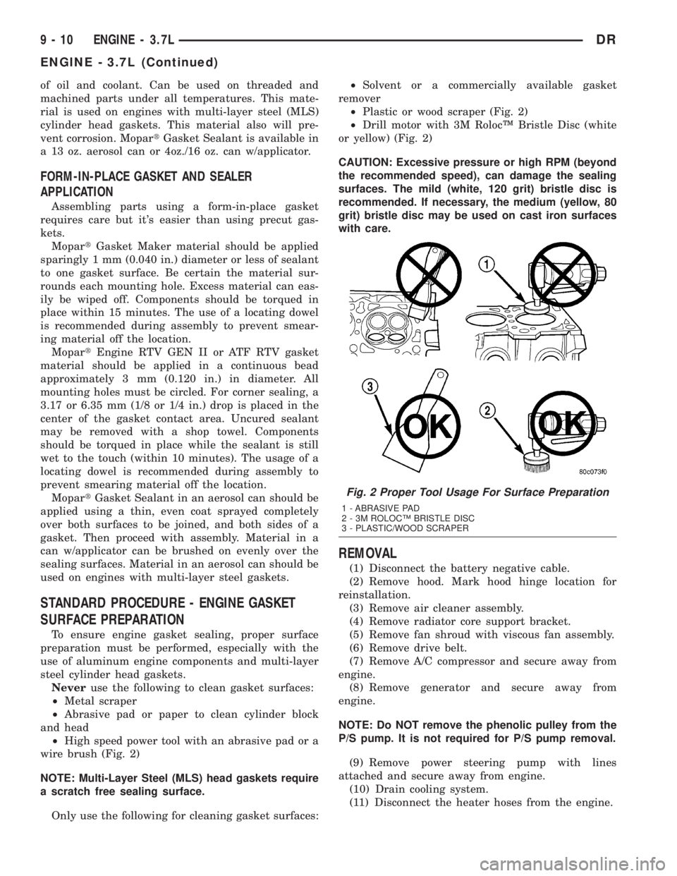
Neveruse the following to clean gasket surfaces:
²Metal scraper
²Abrasive pad or paper to clean cylinder block
and head
²High speed power tool with an abrasive pad or a
wire brush (Fig. 2)
NOTE: Multi-Layer Steel (MLS) head gaskets require
a scratch free sealing surface.
Only use the following for cleaning gasket surfaces:²Solvent or a commercially available gasket
remover
²Plastic or wood scraper (Fig. 2)
²Drill motor with 3M RolocŸ Bristle Disc (white
or yellow) (Fig. 2)
CAUTION: Excessive pressure or high RPM (beyond
the recommended speed), can damage the sealing
surfaces. The mild (white, 120 grit) bristle disc is
recommended. If necessary, the medium (yellow, 80
grit) bristle disc may be used on cast iron surfaces
with care.
REMOVAL
(1) Disconnect the battery negative cable.
(2) Remove hood. Mark hood hinge location for
reinstallation.
(3) Remove air cleaner assembly.
(4) Remove radiator core support bracket.
(5) Remove fan shroud with viscous fan assembly.
(6) Remove drive belt.
(7) Remove A/C compressor and secure away from
engine.
(8) Remove generator and secure away from
engine.
NOTE: Do NOT remove the phenolic pulley from the
P/S pump. It is not required for P/S pump removal.
(9) Remove power steering pump with lines
attached and secure away from engine.
(10) Drain cooling system.
(11) Disconnect the heater hoses from the engine.
Fig. 2 Proper Tool Usage For Surface Preparation
1 - ABRASIVE PAD
2 - 3M ROLOCŸ BRISTLE DISC
3 - PLASTIC/WOOD SCRAPER
9 - 10 ENGINE - 3.7LDR
ENGINE - 3.7L (Continued)