2003 DODGE RAM turn signal
[x] Cancel search: turn signalPage 390 of 2895

²Battery voltage
²Engine coolant temperature sensor
²Crankshaft position sensor
²Intake manifold air temperature sensor
²Manifold absolute pressure (MAP) sensor
²Throttle position sensor (TPS)
²Camshaft position sensor signal
The PCM monitors the crankshaft position sensor.
If the PCM does not receive a crankshaft position
sensor signal within 3 seconds of cranking the
engine, it will shut down the fuel injection system.
The fuel pump is activated by the PCM through
the fuel pump relay.
Voltage is applied to the fuel injectors with the
ASD relay via the PCM. The PCM will then control
the injection sequence and injector pulse width by
turning the ground circuit to each individual injector
on and off.
The PCM determines the proper ignition timing
according to input received from the crankshaft posi-
tion sensor.
ENGINE WARM-UP MODE
This is an Open Loop mode. During engine warm-
up, the PCM receives inputs from:
²Battery voltage
²Crankshaft position sensor
²Engine coolant temperature sensor
²Intake manifold air temperature sensor
²Manifold absolute pressure (MAP) sensor
²Throttle position sensor (TPS)
²Camshaft position sensor signal
²Park/neutral switch (gear indicator signalÐauto.
trans. only)
²Air conditioning select signal (if equipped)
²Air conditioning request signal (if equipped)
Based on these inputs the following occurs:
²Voltage is applied to the fuel injectors with the
ASD relay via the PCM. The PCM will then control
the injection sequence and injector pulse width by
turning the ground circuit to each individual injector
on and off.
²The PCM adjusts engine idle speed through the
idle air control (IAC) motor and adjusts ignition tim-
ing.
²The PCM operates the A/C compressor clutch
through the A/C compressor clutch relay. This is done
if A/C has been selected by the vehicle operator and
specified pressures are met at the high and low±pres-
sure A/C switches. Refer to Heating and Air Condi-
tioning for additional information.
²When engine has reached operating tempera-
ture, the PCM will begin monitoring O2S sensor
input. The system will then leave the warm-up mode
and go into closed loop operation.IDLE MODE
When the engine is at operating temperature, this
is a Closed Loop mode. At idle speed, the PCM
receives inputs from:
²Air conditioning select signal (if equipped)
²Air conditioning request signal (if equipped)
²Battery voltage
²Crankshaft position sensor
²Engine coolant temperature sensor
²Intake manifold air temperature sensor
²Manifold absolute pressure (MAP) sensor
²Throttle position sensor (TPS)
²Camshaft position sensor signal
²Battery voltage
²Park/neutral switch (gear indicator signalÐauto.
trans. only)
²Oxygen sensors
Based on these inputs, the following occurs:
²Voltage is applied to the fuel injectors with the
ASD relay via the PCM. The PCM will then control
injection sequence and injector pulse width by turn-
ing the ground circuit to each individual injector on
and off.
²The PCM monitors the O2S sensor input and
adjusts air-fuel ratio by varying injector pulse width.
It also adjusts engine idle speed through the idle air
control (IAC) motor.
²The PCM adjusts ignition timing by increasing
and decreasing spark advance.
²The PCM operates the A/C compressor clutch
through the A/C compressor clutch relay. This is done
if A/C has been selected by the vehicle operator and
specified pressures are met at the high and low±pres-
sure A/C switches. Refer to Heating and Air Condi-
tioning for additional information.
CRUISE MODE
When the engine is at operating temperature, this
is a Closed Loop mode. At cruising speed, the PCM
receives inputs from:
²Air conditioning select signal (if equipped)
²Air conditioning request signal (if equipped)
²Battery voltage
²Engine coolant temperature sensor
²Crankshaft position sensor
²Intake manifold air temperature sensor
²Manifold absolute pressure (MAP) sensor
²Throttle position sensor (TPS)
²Camshaft position sensor signal
²Park/neutral switch (gear indicator signalÐauto.
trans. only)
²Oxygen (O2S) sensors
Based on these inputs, the following occurs:
²Voltage is applied to the fuel injectors with the
ASD relay via the PCM. The PCM will then adjust
DRELECTRONIC CONTROL MODULES 8E - 9
POWERTRAIN CONTROL MODULE (Continued)
Page 391 of 2895

the injector pulse width by turning the ground circuit
to each individual injector on and off.
²The PCM monitors the O2S sensor input and
adjusts air-fuel ratio. It also adjusts engine idle
speed through the idle air control (IAC) motor.
²The PCM adjusts ignition timing by turning the
ground path to the coil(s) on and off.
²The PCM operates the A/C compressor clutch
through the clutch relay. This happens if A/C has
been selected by the vehicle operator and requested
by the A/C thermostat.
ACCELERATION MODE
This is an Open Loop mode. The PCM recognizes
an abrupt increase in throttle position or MAP pres-
sure as a demand for increased engine output and
vehicle acceleration. The PCM increases injector
pulse width in response to increased throttle opening.
DECELERATION MODE
When the engine is at operating temperature, this
is an Open Loop mode. During hard deceleration, the
PCM receives the following inputs.
²Air conditioning select signal (if equipped)
²Air conditioning request signal (if equipped)
²Battery voltage
²Engine coolant temperature sensor
²Crankshaft position sensor
²Intake manifold air temperature sensor
²Manifold absolute pressure (MAP) sensor
²Throttle position sensor (TPS)
²Camshaft position sensor signal
²Park/neutral switch (gear indicator signalÐauto.
trans. only)
²Vehicle speed
If the vehicle is under hard deceleration with the
proper rpm and closed throttle conditions, the PCM
will ignore the oxygen sensor input signal. The PCM
will enter a fuel cut-off strategy in which it will not
supply a ground to the injectors. If a hard decelera-
tion does not exist, the PCM will determine the
proper injector pulse width and continue injection.
Based on the above inputs, the PCM will adjust
engine idle speed through the idle air control (IAC)
motor.
The PCM adjusts ignition timing by turning the
ground path to the coil on and off.
WIDE OPEN THROTTLE MODE
This is an Open Loop mode. During wide open
throttle operation, the PCM receives the following
inputs.
²Battery voltage
²Crankshaft position sensor
²Engine coolant temperature sensor
²Intake manifold air temperature sensor
²Manifold absolute pressure (MAP) sensor²Throttle position sensor (TPS)
²Camshaft position sensor signal
During wide open throttle conditions, the following
occurs:
²Voltage is applied to the fuel injectors with the
ASD relay via the PCM. The PCM will then control
the injection sequence and injector pulse width by
turning the ground circuit to each individual injector
on and off. The PCM ignores the oxygen sensor input
signal and provides a predetermined amount of addi-
tional fuel. This is done by adjusting injector pulse
width.
²The PCM adjusts ignition timing by turning the
ground path to the coil(s) on and off.
IGNITION SWITCH OFF MODE
When ignition switch is turned to OFF position,
the PCM stops operating the injectors, ignition coil,
ASD relay and fuel pump relay.
DESCRIPTION - 5 VOLT SUPPLIES
Two different Powertrain Control Module (PCM)
five volt supply circuits are used; primary and sec-
ondary.
DESCRIPTION - IGNITION CIRCUIT SENSE
This circuit ties the ignition switch to the Power-
train Control Module (PCM).
DESCRIPTION - POWER GROUNDS
The Powertrain Control Module (PCM) has 2 main
grounds. Both of these grounds are referred to as
power grounds. All of the high-current, noisy, electri-
cal devices are connected to these grounds as well as
all of the sensor returns. The sensor return comes
into the sensor return circuit, passes through noise
suppression, and is then connected to the power
ground.
The power ground is used to control ground cir-
cuits for the following PCM loads:
²Generator field winding
²Fuel injectors
²Ignition coil(s)
²Certain relays/solenoids
²Certain sensors
DESCRIPTION - SENSOR RETURN
The Sensor Return circuits are internal to the Pow-
ertrain Control Module (PCM).
Sensor Return provides a low±noise ground refer-
ence for all engine control system sensors. Refer to
Power Grounds for more information.
8E - 10 ELECTRONIC CONTROL MODULESDR
POWERTRAIN CONTROL MODULE (Continued)
Page 392 of 2895

OPERATION
OPERATION - PCM
The PCM operates the fuel system. The PCM is a
pre-programmed, triple microprocessor digital com-
puter. It regulates ignition timing, air-fuel ratio,
emission control devices, charging system, certain
transmission features, speed control, air conditioning
compressor clutch engagement and idle speed. The
PCM can adapt its programming to meet changing
operating conditions.
The PCM receives input signals from various
switches and sensors. Based on these inputs, the
PCM regulates various engine and vehicle operations
through different system components. These compo-
nents are referred to as Powertrain Control Module
(PCM) Outputs. The sensors and switches that pro-
vide inputs to the PCM are considered Powertrain
Control Module (PCM) Inputs.
The PCM adjusts ignition timing based upon
inputs it receives from sensors that react to: engine
rpm, manifold absolute pressure, engine coolant tem-
perature, throttle position, transmission gear selec-
tion (automatic transmission), vehicle speed, power
steering pump pressure, and the brake switch.
The PCM adjusts idle speed based on inputs it
receives from sensors that react to: throttle position,
vehicle speed, transmission gear selection, engine
coolant temperature and from inputs it receives from
the air conditioning clutch switch and brake switch.
Based on inputs that it receives, the PCM adjusts
ignition coil dwell. The PCM also adjusts the gener-
ator charge rate through control of the generator
field and provides speed control operation.
NOTE: PCM Inputs:
²ABS module (if equipped)
²A/C request (if equipped with factory A/C)
²A/C select (if equipped with factory A/C)
²A/C pressure transducer
²Auto shutdown (ASD) sense
²Battery temperature sensor
²Battery voltage
²Brake switch
²J1850 bus (+) circuits
²J1850 bus (-) circuits
²Camshaft position sensor signal
²Crankshaft position sensor
²Data link connection for DRB scan tool
²EATX module (if equipped)
²Engine coolant temperature sensor
²Fuel level (through J1850 circuitry)
²Generator (battery voltage) output
²Ignition circuit sense (ignition switch in on/off/
crank/run position)²Intake manifold air temperature sensor
²Knock sensors (2 on 3.7L engine)
²Leak detection pump (switch) sense (if equipped)
²Manifold absolute pressure (MAP) sensor
²Oil pressure
²Oxygen sensors
²Park/neutral switch (auto. trans. only)
²Power ground
²Power steering pressure switch (if equipped)
²Sensor return
²Signal ground
²Speed control multiplexed single wire input
²Throttle position sensor
²Transfer case switch (4WD range position)
²Vehicle speed signal
NOTE: PCM Outputs:
²A/C clutch relay
²Auto shutdown (ASD) relay
²J1850 bus (+/-) circuits for: speedometer, voltme-
ter, fuel gauge, oil pressure gauge/lamp, engine temp.
gauge and speed control warn. lamp
²Data link connection for DRB scan tool
²EGR valve control solenoid (if equipped)
²EVAP canister purge solenoid
²Five volt sensor supply (primary)
²Five volt sensor supply (secondary)
²Fuel injectors
²Fuel pump relay
²Generator field driver (-)
²Generator field driver (+)
²Idle air control (IAC) motor
²Ignition coil(s)
²Leak detection pump (if equipped)
²Malfunction indicator lamp (Check engine lamp).
Driven through J1850 circuits.
²Oxygen sensor heater relays
²Oxygen sensors (pulse width modulated)
²Radiator cooling fan relay (pulse width modu-
lated)
²Speed control vacuum solenoid
²Speed control vent solenoid
²Tachometer (if equipped). Driven through J1850
circuits.
²Transmission convertor clutch circuit. Driven
through J1850 circuits.
OPERATION - 5 VOLT SUPPLIES
Primary 5±volt supply:
²supplies the required 5 volt power source to the
Crankshaft Position (CKP) sensor.
²supplies the required 5 volt power source to the
Camshaft Position (CMP) sensor.
²supplies a reference voltage for the Manifold
Absolute Pressure (MAP) sensor.
DRELECTRONIC CONTROL MODULES 8E - 11
POWERTRAIN CONTROL MODULE (Continued)
Page 394 of 2895

(2) Tighten bolts. Refer to torque specifications.
(3) Check pin connectors in the PCM and the three
32±way connectors (four 38±way connectors if
equipped with NGC) for corrosion or damage. Also,
the pin heights in connectors should all be same.
Repair as necessary before installing connectors.
(4) Install three 32±way connectors (four 38±way
connectors if equipped with NGC).
(5) Install cover over electrical connectors. Cover
snaps onto PCM.
(6) Install negative battery cable.
(7) Use the DRB scan tool to reprogram new PCM
with vehicles original Vehicle Identification Number
(VIN) and original vehicle mileage.
SENTRY KEY IMMOBILIZER
MODULE
DESCRIPTION
The Sentry Key Immobilizer Module (SKIM) con-
tains a Radio Frequency (RF) transceiver and a cen-
tral processing unit, which includes the Sentry Key
Immobilizer System (SKIS) program logic. The SKIS
programming enables the SKIM to program and
retain in memory the codes of at least two, but no
more than eight electronically coded Sentry Key
transponders. The SKIS programming also enables
the SKIM to communicate over the Programmable
Communication Interface (PCI) bus network with the
Powertrain Control Module (PCM), and/or the
DRBIIItscan tool.
OPERATION
The SKIM transmits and receives RF signals
through a tuned antenna enclosed within a molded
plastic ring that is integral to the SKIM housing.
When the SKIM is properly installed on the steering
column, the antenna ring is oriented around the igni-
tion lock cylinder housing. This antenna ring must be
located within eight millimeters (0.31 inches) of the
Sentry Key in order to ensure proper RF communica-
tion between the SKIM and the Sentry Key tran-
sponder.
For added system security, each SKIM is pro-
grammed with a unique ªSecret Keyº code and a
security code. The SKIM keeps the ªSecret Keyº code
in memory. The SKIM also sends the ªSecret Keyº
code to each of the programmed Sentry Key tran-
sponders. The security code is used by the assembly
plant to access the SKIS for initialization, or by the
dealer technician to access the system for service.
The SKIM also stores in its memory the Vehicle
Identification Number (VIN), which it learns through
a PCI bus message from the PCM during initializa-
tion.The SKIM and the PCM both use software that
includes a rolling code algorithm strategy, which
helps to reduce the possibility of unauthorized SKIS
disarming. The rolling code algorithm ensures secu-
rity by preventing an override of the SKIS through
the unauthorized substitution of the SKIM or the
PCM. However, the use of this strategy also means
that replacement of either the SKIM or the PCM
units will require a system initialization procedure to
restore system operation.
When the ignition switch is turned to the ON or
START positions, the SKIM transmits an RF signal
to excite the Sentry Key transponder. The SKIM then
listens for a return RF signal from the transponder
of the Sentry Key that is inserted in the ignition lock
cylinder. If the SKIM receives an RF signal with
valid ªSecret Keyº and transponder identification
codes, the SKIM sends a ªvalid keyº message to the
PCM over the PCI bus. If the SKIM receives an
invalid RF signal or no response, it sends ªinvalid
keyº messages to the PCM. The PCM will enable or
disable engine operation based upon the status of the
SKIM messages.
The SKIM also sends messages to the Instrument
Cluster which controls the VTSS indicator LED. The
SKIM sends messages to the Instrument Cluster to
turn the LED on for about three seconds when the
ignition switch is turned to the ON position as a bulb
test. After completion of the bulb test, the SKIM
sends bus messages to keep the LED off for a dura-
tion of about one second. Then the SKIM sends mes-
sages to turn the LED on or off based upon the
results of the SKIS self-tests. If the VTSS indicator
LED comes on and stays on after the bulb test, it
indicates that the SKIM has detected a system mal-
function and/or that the SKIS has become inopera-
tive.
If the SKIM detects an invalid key when the igni-
tion switch is turned to the ON position, it sends
messages to flash the VTSS indicator LED. The
SKIM can also send messages to flash the LED as an
indication to the customer that the SKIS has been
placed in it's ªCustomer Learnº programming mode.
See Sentry Key Immobilizer System Transponder
Programming in this section for more information on
the ªCustomer Learnº programming mode.
For diagnosis or initialization of the SKIM and the
PCM, a DRBIIItscan tool and the proper Powertrain
Diagnostic Procedures manual are required. The
SKIM cannot be repaired and, if faulty or damaged,
the unit must be replaced.
DRELECTRONIC CONTROL MODULES 8E - 13
POWERTRAIN CONTROL MODULE (Continued)
Page 397 of 2895

²Diagnostic Requests
²Manual Transmission and Brake Applied
²PRNDL
²Ignition Status
²ABS Messages
Once the TCCM determines that a requested shift
is allowed, it actuates the bi-directional shift motor
as necessary to achieve the desired transfer case
operating mode. The TCCM also monitors the mode
sensor while controlling the shift motor to determine
the status of the shift attempt.
Several items can cause the requested shift not to
be completed. If the TCCM has recognized a fault
(DTC) of some variety, it will begin operation in one
of four Functionality Levels. These levels are:
²Level Zero- Normal Operation.
²Level One- Only Mode Shifts Are Allowed.
²Level Two- Only Mode Shifts and Shifts Into
LOW Are Allowed (No Neutral Shifts Are Allowed).
²Level Three- No Shifts Are Allowed
The TCCM can also be operating in one of three
possible power modes. These power modes are:
²Full Power Modeis the normal operational
mode of the module. This mode is achieved by normal
PCI bus traffic being present and the ignition being
in the RUN position.
²Reduced Power Modewill be entered when
the ignition has been powered off. In this state, the
module will shut down power supplied to external
devices, and to electronic interface inputs and out-
puts. From this state the module can enter either
Sleep Mode or Full Power Mode. To enter this mode,
the module must receive an ignition message denot-
ing that the ignition is off, or not receive any mes-
sages for 5 0.5 seconds. To exit this mode, themodule must receive one ignition message that
denotes that the ignition is in the RUN position.
²Sleep Modewill be entered, from the Reduced
Power Mode, when no PCI traffic has been sensed for
20 1 seconds. If during Sleep Mode the module
detects PCI bus traffic, it will revert to the Reduced
Power mode while monitoring for ignition messages.
It will remain in this state as long as there is traffic
other than run or start messages, and will return to
Sleep mode if the bus goes without traffic for 20 1
seconds.
SHIFT REQUIREMENTS
If the TCCM is in full power mode and at function-
ality level zero, it uses the following criteria to deter-
mine if a shift is allowed.
If any of the driver controllable conditions are not
met once the shift request is recognized, the TCCM
will solidly illuminate the source position's LED and
flash the desired position's LED for all shifts except
NEUTRAL. The NEUTRAL shift LED strategy will
be discussed later.
Mode shiftswill be allowed regardless of trans-
mission gear or vehicle speed, whenever the following
conditions are met:
²Front and rear wheel speed are within 21 km/hr
(13 mph).
²A change in the Selector switch state indicates
that a mode shift has been requested.
²A valid mode sensor signal is being sensed by
the TCCM.
²Proper transmit/receive messages are occurring
on the PCI bus.
²Ignition key switch is in the RUN position.
Range shiftswill be allowed only if all of the fol-
lowing conditions are met:
²Front and rear wheel speed are within 21 km/hr
(13 mph).
²A change in the Selector Switch state indicating
a range shift has been requested.
²Transmission in NEUTRAL signal must be rec-
ognized for at least 1.5 seconds 100 msec. (Automat-
ic transmissions only)
²Proper transmit/receive messages are occurring
on the PCI bus.
²Clutch signal is recognized for 500 msec 50
msec (Manual transmissions only).
²Vehicle speed is less than or equal to 4.8 km/hr
(3 miles per hour).
²Ignition key switch is in the RUN position.
²A valid mode sensor signal is being sensed by
the TCCM.
Ashift into transfer case Neutralwill be
allowed only if all of the following conditions are met:
²Front and rear wheel speed are within 21 km/hr
(13 mph).
Fig. 9 Transfer Case Control Module (TCCM)
Location
1 - INSTRUMENT PANEL
2 - TRANSFER CASE CONTROL MODULE (TCCM)
3 - TRANSFER CASE SELECTOR SWITCH
8E - 16 ELECTRONIC CONTROL MODULESDR
TRANSFER CASE CONTROL MODULE (Continued)
Page 452 of 2895

(2) Connect the new heating element electrical
connectors (Fig. 2).
(3) Connect the battery negative cable.
(4) Verify heated seat system operation.
(5) Install the appropriate seat cushion or seat
back trim cover. Make certain the seat wire harness
is correctly routed through the seat and seat back.
HEATED SEAT SENSOR
DESCRIPTION
The heated seat temperature sensor is a Negative
Temperature Coefficient (NTC) thermistor. One tem-
perature sensor is used for each seat. This tempera-
ture sensor is located in the seat cushion heating
element on all models.
The heated seat temperature sensor cannot be
repaired or adjusted and must be replaced if defec-
tive. The heated seat cushion element must be
replaced if the temperature sensor is defective. Refer
to the procedure in this section of the service man-
ual.
OPERATION
When the temperature of the seat cushion cover
rises, the resistance of the sensor decreases. The
heated seat module supplies five-volts to one side of
each sensor, and monitors the voltage drop through
the sensor on a return circuit. The heated seat mod-
ule uses this temperature sensor input to monitorthe temperature of the seat, and regulates the cur-
rent flow to the seat heating elements accordingly.
DIAGNOSIS AND TESTING - HEATED SEAT
SENSOR
NOTE: Any resistance values (OHMSV) given in the
following text are supplied using the automatic
range generated by a FLUKETautomotive meter. If
another type of measuring device is used, the val-
ues generated may not be the same as the results
shown here, or may have to be converted to the
range used here.
(1) Position the driver seat in the full rearward
position.
(2) Unclip the heated seat module from the bottom
of the drivers seat cushion pan.
(3) Back-probe the heated seat module wire har-
ness connector, do not disconnect. Check cavity (#7
for passenger, #8 for driver seat) for a range in volt-
age from approx. 1.72 ± 3.0 volts. It should be within
this range, If OK check the heated seat element. If
NOT OK, check for the proper 5 volt supply to the
heated seat sensor, from the module. Refer to Wiring
for specific information. If 5 volts is not being sup-
plied to the sensor from the module, replace the
heated seat module.
(4) Test the seat wire harness between the heated
seat module connector and the heated seat wire har-
ness connector for shorted or open circuits. If OK,
refer toDiagnosis and Testing the Heated Seat
Modulein Electronic Control Modules, for the
proper heated seat module diagnosis and testing pro-
cedures. If not OK, repair the shorted or open heated
seat wire harness as required.
REMOVAL
(1) For heated seat sensor replacement procedure
(Refer to 8 - ELECTRICAL/HEATED SEATS/
HEATED SEAT ELEMENT - REMOVAL).
HEATED SEAT SWITCH
DESCRIPTION
The momentary, bidirectional rocker-type heated
seat switch (Fig. 4) provides a resistor-multiplexed
signal to the heated seat module via a mux circuit.
Each switch has a center neutral position and
momentary Low and High positions so that both the
driver and the front seat passenger can select a pre-
ferred level of seat heating. Each heated seat switch
has two Light-Emitting Diode (LED) indicator lamps,
which indicate the selected mode (Low or High) of
the seat heater. These indicator lamps also provide
Fig. 3 Heating Element Installation
1 - ORIGINAL (INOPERATIVE) HEATING ELEMENT
2 - REPLACEMENT HEATING ELEMENT
DRHEATED SEAT SYSTEM 8G - 7
HEATED SEAT ELEMENT (Continued)
Page 453 of 2895
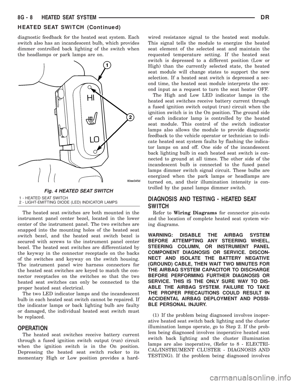
diagnostic feedback for the heated seat system. Each
switch also has an incandescent bulb, which provides
dimmer controlled back lighting of the switch when
the headlamps or park lamps are on.
The heated seat switches are both mounted in the
instrument panel center bezel, located in the lower
center of the instrument panel. The two switches are
snapped into the mounting holes of the heated seat
switch bezel, and the heated seat switch bezel is
secured with screws to the instrument panel center
bezel. The heated seat switches are differentiated by
the keyway in the connector receptacle on the backs
of the switches and keyway on the switch housing.
The instrument panel wire harness connectors for
the heated seat switches are keyed to match the con-
nector receptacles on the switches so that the two
heated seat switches can only be connected to the
proper heated seat electrical.
The two LED indicator lamps and the incandescent
bulb in each heated seat switch cannot be repaired. If
the indicator lamps or back lighting bulb are faulty
or damaged, the individual heated seat switch must
be replaced.
OPERATION
The heated seat switches receive battery current
through a fused ignition switch output (run) circuit
when the ignition switch is in the On position.
Depressing the heated seat switch rocker to its
momentary High or Low position provides a hard-wired resistance signal to the heated seat module.
This signal tells the module to energize the heated
seat element of the selected seat and maintain the
requested temperature setting. If the heated seat
switch is depressed to a different position (Low or
High) than the currently selected state, the heated
seat module will change states to support the new
selection. If a heated seat switch is depressed a sec-
ond time, the heated seat module interprets the sec-
ond input as a request to turn the seat heater OFF.
The High and Low LED indicator lamps in the
heated seat switches receive battery current through
a fused ignition switch output (run) circuit when the
ignition switch is in the On position. The ground side
of each indicator lamp is controlled by the heated
seat module. This control of the switch indicator
lamps also allows the module to provide diagnostic
feedback to the vehicle operator or technician to indi-
cate heated seat system faults by flashing the indica-
tor lamps on and off. One side of the incandescent
back lighting bulb in each heated seat switch is con-
nected to ground at all times. The other side of the
incandescent bulb is connected to the fused panel
lamps dimmer switch signal circuit. These bulbs are
energized when the park lamps or headlamps are
turned on, and their illumination intensity is con-
trolled by the panel lamps dimmer switch.
DIAGNOSIS AND TESTING - HEATED SEAT
SWITCH
Refer toWiring Diagramsfor connector pin-outs
and the location of complete heated seat system wir-
ing diagrams.
WARNING: DISABLE THE AIRBAG SYSTEM
BEFORE ATTEMPTING ANY STEERING WHEEL,
STEERING COLUMN, OR INSTRUMENT PANEL
COMPONENT DIAGNOSIS OR SERVICE. DISCON-
NECT AND ISOLATE THE BATTERY NEGATIVE
(GROUND) CABLE, THEN WAIT TWO MINUTES FOR
THE AIRBAG SYSTEM CAPACITOR TO DISCHARGE
BEFORE PERFORMING FURTHER DIAGNOSIS OR
SERVICE. THIS IS THE ONLY SURE WAY TO DIS-
ABLE THE AIRBAG SYSTEM. FAILURE TO TAKE
THE PROPER PRECAUTIONS COULD RESULT IN
ACCIDENTAL AIRBAG DEPLOYMENT AND POSSI-
BLE PERSONAL INJURY.
(1) If the problem being diagnosed involves inoper-
ative heated seat switch back lighting and the cluster
illumination lamps operate, go to Step 2. If the prob-
lem being diagnosed involves inoperative heated seat
switch back lighting and the cluster illumination
lamps are also inoperative, (Refer to 8 - ELECTRI-
CAL/INSTRUMENT CLUSTER - DIAGNOSIS AND
TESTING). If the problem being diagnosed involves
Fig. 4 HEATED SEAT SWITCH
1 - HEATED SEAT SWITCH
2 - LIGHT-EMITTING DIODE (LED) INDICATOR LAMPS
8G - 8 HEATED SEAT SYSTEMDR
HEATED SEAT SWITCH (Continued)
Page 454 of 2895

inoperative heated seat switch indicator lamps and
the heated seat elements do not heat, proceed. If the
problem being diagnosed involves inoperative heated
seat switch indicator lamps and the heated seat ele-
ments do heat, go to Step 6. If the problem being
diagnosed involves a heated seat switch indicator
lamp that remains illuminated after the heated seat
has been turned Off, (Refer to 8 - ELECTRICAL/
ELECTRONIC CONTROL MODULES/MEMORY
HEATED SEAT/MIRROR MODULE - DIAGNOSIS
AND TESTING).
(2) Disconnect and isolate the battery negative
cable. Remove the heated seat switch and bezel unit
from the instrument panel. Disconnect the heated
seat switch to be tested. Check for continuity
between the ground circuit cavity of the heated seat
switch and a good ground. There should be continu-
ity. If OK, go to Step 3. If not OK, repair the open
ground circuit to ground as required.
(3) Reconnect the battery negative cable. Turn the
park lamps on with the headlamp switch. Rotate the
panel lamps dimmer thumb wheel on the headlamp
switch upward to just before the interior lamps
detent. Check for battery voltage at the fused panel
lamps dimmer circuit cavity of the heated seat
switch. If OK, go to Step 4. If not OK, repair the
open fused panel lamps dimmer switch signal circuit
to the fuse in the Integrated Power Module as
required.
(4) Turn the ignition switch to the On position.
Check for battery voltage at the fused ignition switch
output (run) circuit cavity of the heated seat switch.
If OK, go to Step 5. If not OK, repair the open fused
ignition switch output (run) circuit as required.
(5) Check the continuity and resistance values of
the heated seat switch in the Neutral, Low and High
positions as shown in the Heated Seat Switch Conti-
nuity chart. If OK, refer to Step 6. If not OK, replace
the faulty heated seat switch.
HEATED SEAT SWITCH CONTINUITY
Switch PositionContinuity
BetweenResistance
Neutral 4 & 6 2.2 Kilohms
Low 4 & 6 .415 Kilohms
High 4 & 6 33 Ohms(6) Replace the inoperative heated seat switch
with a known good unit and test the operation of the
switch indicator lamps. If OK, discard the faulty
heated seat switch. If not OK, (Refer to 8 - ELEC-
TRICAL/ELECTRONIC CONTROL MODULES/
MEMORY HEATED SEAT/MIRROR MODULE -
DIAGNOSIS AND TESTING).
REMOVAL
(1) Disconnect and isolate the negative battery
cable.
(2) Wait two minutes for the system reserve capac-
itor to discharge before beginning any airbag or
instrument panel service.
(3) Remove the center bezel from the instrument
panel (Refer to 23 - BODY/INSTRUMENT PANEL/
INSTRUMENT PANEL CENTER BEZEL - REMOV-
AL).
(4) Remove the screws that secure the heated seat
switch bezel to the instrument panel center bezel.
(5) Remove the heated seat switch bezel and both
switches from the instrument panel as a unit.
(6) From the back of the heated seat switch bezel,
gently pry the switch free and push the heated seat
switch out through the front of the bezel.
INSTALLATION
NOTE: When installing the heated seat switches, be
certain they are installed in the proper mounting
holes of the heated seat switch bezel. The heated
seat switches are differentiated by the keyway in
the connector receptacle on the backs of the
switches and keyway on the switch housing (Fig.
4).
(1) From the back of the heated seat switch bezel,
gently push the heated seat switch in through the
front of the bezel.
(2) Position the heated seat switch bezel to the
instrument panel center bezel and install the retain-
ing screws.
(3) Install the center bezel on the instrument
panel (Refer to 23 - BODY/INSTRUMENT PANEL/
INSTRUMENT PANEL CENTER BEZEL - INSTAL-
LATION).
(4) Connect the battery negative cable.
(5) Verify vehicle and system operation.
DRHEATED SEAT SYSTEM 8G - 9
HEATED SEAT SWITCH (Continued)