2003 DODGE RAM door lock
[x] Cancel search: door lockPage 503 of 2895

²Driver Door Lock Switch MUX - with
Power Locks
²Fused B(+) - Ignition-Off Draw
²Fused B(+) - Power Lock Feed - with Power
Locks
²Fused Ignition Switch Output (Accessory-
Run)
²Fused Ignition Switch Output (Off-Run-
Start)
²Fused Ignition Switch Output (Run-Start)
²Headlamp Dimmer Switch MUX
²Headlamp Switch MUX
²Horn Relay Control
²Key-In Ignition Switch Sense
²Left Rear Door Ajar Switch Sense
²Panel Lamps Dimmer Switch Signal
²Park Brake Switch Sense
²Passenger Door Ajar Switch Sense
²Passenger Door Lock Switch MUX - with
Power Locks
²Radio Control MUX
²Right Rear Door Ajar Switch Sense
²RKE Supply - with RKE
²Seat Belt Switch Sense
²Transmission Range Sensor MUX - with
Auto Trans
²Turn/Hazard Switch MUX
²Washer/Beam Select Switch MUX
²Wiper Switch MUX
Refer to the appropriate wiring information for
additional details.
HARD WIRED OUTPUTS
The hard wired outputs of the EMIC include the
following:
²Accessory Switch Bank Illumination Driver
²BTSI Driver - with Auto Trans
²Cargo Lamp Driver
²Dome/Overhead Lamp Driver
²Driver Door Unlock Driver - with Power
Locks
²Headlamp Switch Illumination Driver
²Heated Seat Switch Indicator Driver - with
Heated Seats
²Heater-A/C Control Illumination Driver
²Left Door Lock Driver - with Power Locks
²Left Rear Door Unlock Driver - with Power
Locks
²Map/Glove Box Lamp Driver²Radio Illumination Driver
²Right Door Lock Driver - with Power Locks
²Right Door Unlock Driver - with Power
Locks
²Transfer Case Switch Illumination Driver -
with Four-Wheel Drive
Refer to the appropriate wiring information for
additional details.
GROUNDS
The EMIC receives and supplies a ground path to
several switches and sensors through the following
hard wired circuits:
²Ground - Illumination (2 Circuits)
²Ground - Power Lock - with Power Locks
²Ground - Signal
²Headlamp Switch Return
²Multi-Function Switch Return
²Transmission Range Sensor Return - with
Auto Trans
Refer to the appropriate wiring information for
additional details.
COMMUNICATION
The EMIC has provisions for the following commu-
nication circuits:
²PCI Data Bus
²RKE Program Serial Data - with RKE
²RKE Transmit Serial Data - with RKE
Refer to the appropriate wiring information for
additional details.
DIAGNOSIS AND TESTING - INSTRUMENT
CLUSTER
If all of the instrument cluster gauges and/or indi-
cators are inoperative, refer to PRELIMINARY
DIAGNOSIS. If an individual gauge or Programma-
ble Communications Interface (PCI) data bus mes-
sage-controlled indicator is inoperative, refer to
ACTUATOR TEST. If an individual hard wired indi-
cator is inoperative, refer to the diagnosis and testing
information for that specific indicator.
Refer to the appropriate wiring information. The
wiring information includes wiring diagrams, proper
wire and connector repair procedures, details of wire
harness routing and retention, connector pin-out
information and location views for the various wire
harness connectors, splices and grounds.
8J - 10 INSTRUMENT CLUSTERDR
INSTRUMENT CLUSTER (Continued)
Page 506 of 2895
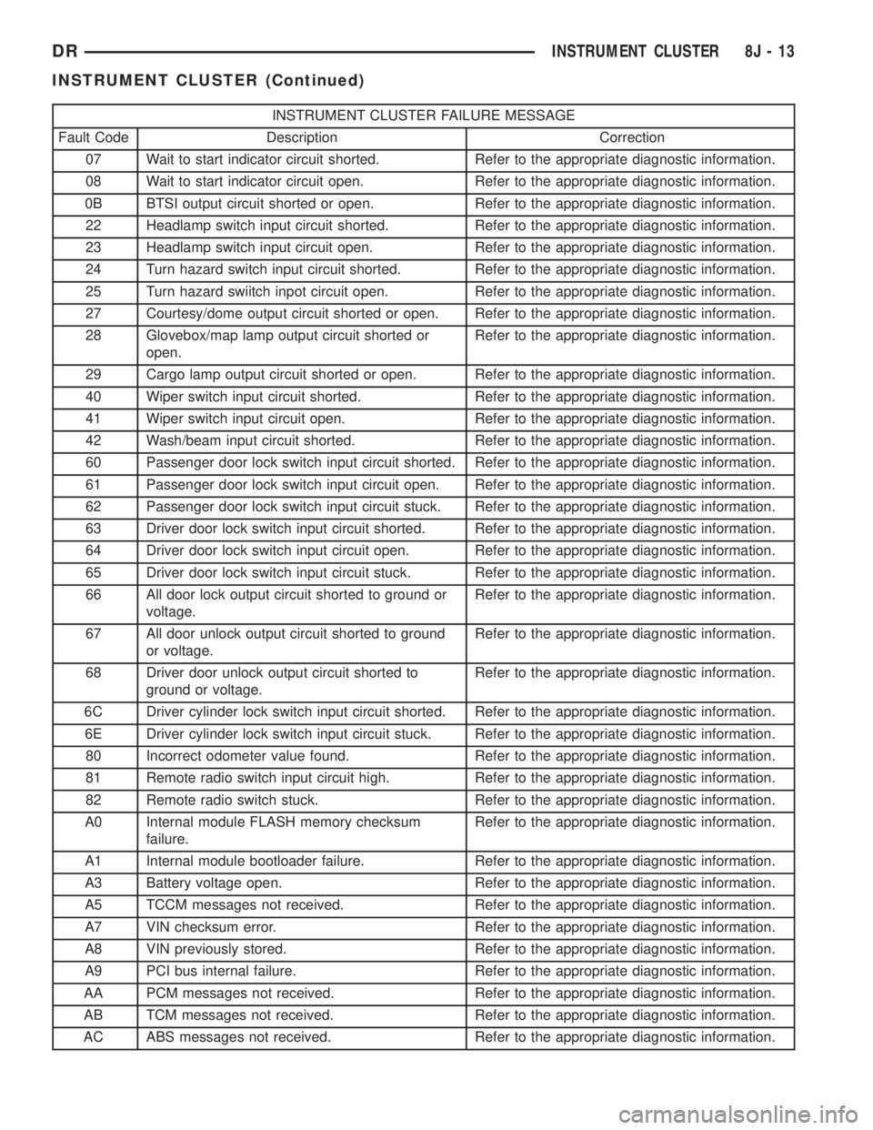
INSTRUMENT CLUSTER FAILURE MESSAGE
Fault Code Description Correction
07 Wait to start indicator circuit shorted. Refer to the appropriate diagnostic information.
08 Wait to start indicator circuit open. Refer to the appropriate diagnostic information.
0B BTSI output circuit shorted or open. Refer to the appropriate diagnostic information.
22 Headlamp switch input circuit shorted. Refer to the appropriate diagnostic information.
23 Headlamp switch input circuit open. Refer to the appropriate diagnostic information.
24 Turn hazard switch input circuit shorted. Refer to the appropriate diagnostic information.
25 Turn hazard swiitch inpot circuit open. Refer to the appropriate diagnostic information.
27 Courtesy/dome output circuit shorted or open. Refer to the appropriate diagnostic information.
28 Glovebox/map lamp output circuit shorted or
open.Refer to the appropriate diagnostic information.
29 Cargo lamp output circuit shorted or open. Refer to the appropriate diagnostic information.
40 Wiper switch input circuit shorted. Refer to the appropriate diagnostic information.
41 Wiper switch input circuit open. Refer to the appropriate diagnostic information.
42 Wash/beam input circuit shorted. Refer to the appropriate diagnostic information.
60 Passenger door lock switch input circuit shorted. Refer to the appropriate diagnostic information.
61 Passenger door lock switch input circuit open. Refer to the appropriate diagnostic information.
62 Passenger door lock switch input circuit stuck. Refer to the appropriate diagnostic information.
63 Driver door lock switch input circuit shorted. Refer to the appropriate diagnostic information.
64 Driver door lock switch input circuit open. Refer to the appropriate diagnostic information.
65 Driver door lock switch input circuit stuck. Refer to the appropriate diagnostic information.
66 All door lock output circuit shorted to ground or
voltage.Refer to the appropriate diagnostic information.
67 All door unlock output circuit shorted to ground
or voltage.Refer to the appropriate diagnostic information.
68 Driver door unlock output circuit shorted to
ground or voltage.Refer to the appropriate diagnostic information.
6C Driver cylinder lock switch input circuit shorted. Refer to the appropriate diagnostic information.
6E Driver cylinder lock switch input circuit stuck. Refer to the appropriate diagnostic information.
80 Incorrect odometer value found. Refer to the appropriate diagnostic information.
81 Remote radio switch input circuit high. Refer to the appropriate diagnostic information.
82 Remote radio switch stuck. Refer to the appropriate diagnostic information.
A0 Internal module FLASH memory checksum
failure.Refer to the appropriate diagnostic information.
A1 Internal module bootloader failure. Refer to the appropriate diagnostic information.
A3 Battery voltage open. Refer to the appropriate diagnostic information.
A5 TCCM messages not received. Refer to the appropriate diagnostic information.
A7 VIN checksum error. Refer to the appropriate diagnostic information.
A8 VIN previously stored. Refer to the appropriate diagnostic information.
A9 PCI bus internal failure. Refer to the appropriate diagnostic information.
AA PCM messages not received. Refer to the appropriate diagnostic information.
AB TCM messages not received. Refer to the appropriate diagnostic information.
AC ABS messages not received. Refer to the appropriate diagnostic information.
DRINSTRUMENT CLUSTER 8J - 13
INSTRUMENT CLUSTER (Continued)
Page 539 of 2895
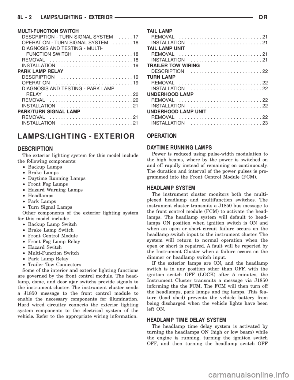
MULTI-FUNCTION SWITCH
DESCRIPTION - TURN SIGNAL SYSTEM.....17
OPERATION - TURN SIGNAL SYSTEM.......18
DIAGNOSIS AND TESTING - MULTI-
FUNCTION SWITCH...................18
REMOVAL.............................18
INSTALLATION.........................19
PARK LAMP RELAY
DESCRIPTION.........................19
OPERATION...........................19
DIAGNOSIS AND TESTING - PARK LAMP
RELAY..............................20
REMOVAL.............................20
INSTALLATION.........................21
PARK/TURN SIGNAL LAMP
REMOVAL.............................21
INSTALLATION.........................21TAIL LAMP
REMOVAL.............................21
INSTALLATION.........................21
TAIL LAMP UNIT
REMOVAL.............................21
INSTALLATION.........................21
TRAILER TOW WIRING
DESCRIPTION.........................22
TURN LAMP
REMOVAL.............................22
INSTALLATION.........................22
UNDERHOOD LAMP
REMOVAL.............................22
INSTALLATION.........................22
UNDERHOOD LAMP UNIT
REMOVAL.............................22
INSTALLATION.........................23
LAMPS/LIGHTING - EXTERIOR
DESCRIPTION
The exterior lighting system for this model include
the following components:
²Backup Lamps
²Brake Lamps
²Daytime Running Lamps
²Front Fog Lamps
²Hazard Warning Lamps
²Headlamps
²Park Lamps
²Turn Signal Lamps
Other components of the exterior lighting system
for this model include:
²Backup Lamp Switch
²Brake Lamp Switch
²Front Control Module
²Front Fog Lamp Relay
²Hazard Switch
²Multi-Function Switch
²Park Lamp Relay
²Trailer Tow Connectors
Some of the interior and exterior lighting functions
are governed by the front control module. The head-
lamp, dome, and door ajar switchs provide signals to
the instrument cluster. The instrument cluster sends
a J1850 message to the front control module to
enable the necessary components for illumination.
Hard wired circuitry connects the exterior lighting
system components to the electrical system of the
vehicle. Refer to the appropriate wiring information.
OPERATION
DAYTIME RUNNING LAMPS
Power is reduced using pulse-width modulation to
the high beams, where by the power is switched on
and off rapidly instead of remaining on continuously.
The duration and interval of the power pulses is pro-
grammed into the Front Control Module (FCM).
HEADLAMP SYSTEM
The instrument cluster monitors both the multi-
plexed headlamp and multifunction switches. The
instrument cluster transmits a J1850 bus message to
the front control module (FCM) to activate the head-
lamps. The headlamp system will default to head-
lamps ON position when ignition switch is ON and
when an open or short circuit failure occurs on the
headlamp switch input to the instrument cluster. The
system will return to normal operation when the
open or short is repaired. A fault will be reported by
the Instrument Cluster when a failure occurs on the
dimmer or headlamp switch input.
If the exterior lamps are ON, and the headlamp
switch is in any position other than OFF, with the
ignition switch OFF (LOCK) after 5 minutes, the
Instrument Cluster transmits a message via J1850
informing the the FCM. The FCM will then turn off
the headlamps, park lamps and fog lamps. This fea-
ture (load shed) prevents the vehicle battery from
being discharged when the vehicle lights have been
left ON.
HEADLAMP TIME DELAY SYSTEM
The headlamp time delay system is activated by
turning the headlamps ON (high or low beam) while
the engine is running, turning the ignition switch
OFF, and then turning the headlamp switch OFF
8L - 2 LAMPS/LIGHTING - EXTERIORDR
Page 561 of 2895

LAMPS/LIGHTING - INTERIOR
TABLE OF CONTENTS
page page
DOME LAMP
DESCRIPTION.........................24
OPERATION...........................24
REMOVAL.............................24
INSTALLATION.........................24
DOOR AJAR SWITCH
DESCRIPTION.........................25
OPERATION...........................25GLOVE BOX LAMP/SWITCH
REMOVAL.............................25
INSTALLATION.........................25
READING LAMP
DESCRIPTION.........................26
OPERATION...........................26
REMOVAL.............................26
INSTALLATION.........................26
DOME LAMP
DESCRIPTION
The dome lamp is controlled by the instrument
cluster which provides power at all times, regardless
of the ignition switch position. The ground circuit for
the lamp is switched through the integral dome lamp
switch or through the door ajar switches via the
instrument cluster.
The dome lamp lens and bulb are available for ser-
vice replacement. If either of the lamp switch or bulb
holders is faulty or damaged, the dome lamp assem-
bly must be replaced.
For service of the dome lamp bulb, refer to the
appropriate wiring information.
OPERATION
The dome lamp is activated by the door ajar
switches via the instrument cluster. When all of the
doors are closed, the lamp can be activated by
depressing the lens. When any door is open, depress-
ing the lamp lense to activate the lamp switch will
not turn the lamps off.
The instrument cluster monitors the door ajar
switches. When a door is open the instrument cluster
grounds the low side drivers to turn on the lamp.
Upon closing all doors, the instrument cluster ini-
tiates a 30 second timer. If any of the doors are
opened during the ªtime outº cycle, the instrument
cluster will reset the timer until all doors are closed.
The instrument cluster will faid to off when the doors
are closed and the ignition is turned ON, the time
out expires or the power locks are activated.
REMOVAL
(1) Using a small flat blade, pry the left side (driv-
er's side) of the dome lamp lens downward from
dome lamp.(2) Allow the lens to hang down (Fig. 1), this will
disengage the right side of the lamp (passenger's
side) from the headliner.
(3) Pull the right side of the lamp down and slide
the lamp to the right (Fig. 2).
(4) Separate the lamp from the headliner.
(5) Disengage dome lamp wire connector from body
wire harness.
(6) Separate dome lamp from vehicle.
INSTALLATION
(1) Position dome lamp at headliner.
(2) Connect dome lamp wire connector to body
wire harness.
(3) Position the left side of the lamp in the head-
liner opening and slide lamp to the left (Fig. 1).
(4) Push the right side of the lamp in the head-
liner opening and push the lamp lens up into the
lamp to secure (Fig. 1).
Fig. 1 Dome Lamp Lens
1 - HEADLINER
2 - CONNECTOR
3 - DOME LAMP
4 - LENS
5 - BULB
8L - 24 LAMPS/LIGHTING - INTERIORDR
Page 563 of 2895

(4) Push the glove box lamp and switch unit into
the hole in the mounting bracket on the instrument
panel glove box opening upper reinforcement.
(5) Install the glove box onto the instrument panel.
(Refer to 23 - BODY/INSTRUMENT PANEL/GLOVE
BOX - INSTALLATION) for the procedures.
(6) Close the glove box.
(7) Reconnect the battery negative cable.
READING LAMP
DESCRIPTION
The overhead console in this vehicle is equipped
with two individual reading and courtesy lamps. The
lamp lenses are the only visible components of these
lamps. Each lamp has its own switch, bulb, reflector
and lens within the overhead console.
The overhead console reading and courtesy lamps
are controlled by the instrument cluster which pro-
vides power at all times, regardless of the ignition
switch position. The ground circuit for the lamps is
switched through the integral reading and courtesy
lamp switches or through the door ajar switches.
Each lamp is designed and aimed to provide illumi-
nation that will be directed only to that side of the
vehicle on which the lamp is located.
The reading and courtesy lamp lenses and bulbs
are available for service replacement. The reading
and courtesy lamp switches, bulb holders and wiring
are only available as part of the overhead console
wire harness. If either of the lamp switches or bulb
holders is faulty or damaged, the entire overhead
console wire harness assembly must be replaced.
For service of the reading and courtesy lamp bulbs,
refer to the appropriate wiring information.
OPERATION
All reading and courtesy lamps located in the over-
head console are activated by the door ajar switches
via the instrument cluster. When all of the doors are
closed, these lamps can be individually activated by
depressing the corresponding lens. When any door is
open, depressing the lamp lenses to activate the lamp
switches will not turn the lamps off.
The instrument cluster monitors the door ajar
switches. When a door is open the instrument cluster
grounds the low side drivers to turn on the lamps.
Upon closing all doors, the instrument cluster ini-
tiates a 30 second timer. If any of the doors are
opened during the ªtime outº cycle, the instrument
cluster will reset the timer until all doors are closed.
The instrument cluster will faid to off when the doors
are closed and the ignition is turned ON, the time
out expires or the power locks are activated.
REMOVAL
(1) Disconnect and isolate the battery negative
cable.
(2) Insert a long, narrow, flat-bladed tool between
the curved (outboard) edge of the reading and cour-
tesy lamp lens and the overhead console housing
(Fig. 4).
(3) Gently pry inward and downward against the
lens until the latch tab in the center of the outboard
edge of the reading and courtesy lamp lens is disen-
gaged from the overhead console housing.
(4)
Pull firmly on the lens toward the outboard side
of the vehicle to disengage the two pivot tabs on the
inboard edge of the reading and courtesy lamp lens
are disengaged from the overhead console housing.
(5) Remove the reading and courtesy lamp lens
from the overhead console housing.
INSTALLATION
(1) Position the reading and courtesy lamp lens
onto the overhead console housing.
(2) Align the two pivot tabs on the inboard edge of
the reading and courtesy lamp lens with the two
pivot holes in the overhead console housing.
(3) Push firmly on the lens toward the inboard
side of the vehicle to insert the two pivot tabs on the
inboard edge of the reading and courtesy lamp lens
into the two pivot holes in the overhead console hous-
ing.
(4) Pivot the lens back up into position and press
upward firmly until the latch tab in the center of the
outboard edge of the reading and courtesy lamp lens
snaps back into the overhead console housing.
(5) Reconnect the battery negative cable.
Fig. 4 Overhead Console Reading Lamp Bulb
Removal
1 - LENS
2 - FLAT BLADE
3 - CONSOLE
8L - 26 LAMPS/LIGHTING - INTERIORDR
GLOVE BOX LAMP/SWITCH (Continued)
Page 572 of 2895

(2) Momentarily depress and release the Menu
push button to step through the programmable fea-
tures list. Each programmable feature and its cur-
rently selected option will appear on the EVIC
display in the sequence shown in the Programmable
Features list that follows.
(3) Momentarily depress and release the Step push
button to step through the available options for the
programmable feature being displayed.
(4) The option that last appears in the display
with a programmable feature before exiting the pro-
gramming mode, becomes the newly selected pro-
grammable feature option.
(5) The EVIC exits the programming mode and
returns to its normal operating mode when the C/T
push button is depressed or when the end of the pro-
grammable features menu list is reached, whichever
occurs first.
PROGRAMMABLE FEATURES
²LANGUAGE?- The options include English,
Francaise, Deutsch, Italiana, or Espanol. The default
is English. All EVIC display nomenclature, including
the trip computer functions, warning messages and
the programmable features appear in the selected
language.
²DISPLAY U.S. OR METRIC?- The options
include U.S. and M. The default is U.S. This feature
toggles the trip computer temperature, fuel economy
and odometer display readings between U.S. and
metric units of measure.
²SERVICE INTV. =- The options include from
3200 to 12000 kilometers in 800 kilometer incre-
ments (2000 to 6000 miles in 500 mile increments).
The default is 12000 kilometers (6000 miles). The
selected distance becomes the interval at which the
Perform Service warning message will be displayed
by the EVIC. If a new distance is selected, a second
programmable feature appears,RESET SERVICE
DISTANCE?- The options include No and Yes. The
default is Yes. When Yes is selected, the accumulated
distance since the last previous Perform Service
warning message will be reset to zero because the
service interval has been changed. When No is
selected, the distance until the next Perform Service
warning message is reduced by the accumulated dis-
tance since the last previous message.
²AUTO DOOR LOCKS?- The options include
Yes and No. The default is Yes. When Yes is selected,
all doors lock automatically when vehicle speed
reaches 25 kilometers-per-hour (15 miles-per-hour). If
YES is selected, a second programmable feature
appears,AUTO UNLOCK ON EXIT?- The options
again include Yes and No. The default is No. When
Yes is selected, following each Auto Door Lock event
all doors will automatically unlock when the driverdoor is opened, if the vehicle is stopped and the
transmission gear selector is in Park or Neutral. The
Auto Door Unlock event will only occur once follow-
ing each Auto Door Lock event.
²REMOTE UNLOCK- The options include
Driver Door 1st and All Doors. The default is Driver
Door 1st. When Diver Door 1st is selected, only the
driver door unlocks when the Unlock button of the
Remote Keyless Entry (RKE) transmitter is
depressed once. The Unlock button of the RKE trans-
mitter must be depressed twice to unlock all doors.
When All Doors is selected, all doors unlock when the
Unlock button of the RKE transmitter is depressed
once.
²SOUND HORN ON LOCK?- The options
include On and Off. The default is No. When Yes is
selected, a short horn chirp will provide an audible
confirmation when the RKE receiver recognizes a
valid Lock signal from an RKE transmitter. When No
is selected, no horn chirp will occur with the RKE
Lock event. This feature may be selected indepen-
dent of theFLASH LIGHTS WITH LOCKS?pro-
grammable feature.
²FLASH LIGHTS WITH LOCKS?- The options
include Yes and No. The default is Yes. When Yes is
selected, a single flash of the hazard warning lamps
will provide an optical confirmation when the RKE
receiver recognizes a valid Lock signal from an RKE
transmitter, and two flashes of the same lamps will
occur when the RKE receiver recognizes a valid
Unlock signal from an RKE transmitter. When No is
selected, no lamp flash will occur with the RKE Lock
or Unlock event. This feature may be selected inde-
pendent of theSOUND HORN ON LOCK?pro-
grammable feature.
²HEADLAMP DELAY =- The options include
Off, 30 Sec, 60 Sec, and 90 Sec. The default is 90 Sec.
When a time interval is selected, the headlamps will
remain on for that length of time when the head-
lamps are turned off after the ignition is turned off,
or if the Auto mode is selected on vehicles with the
Auto Headlamps option. When Off is selected, the
headlamp delay feature is disabled.
²TRAIN REMOTE- When this feature is
selected the driver can choose to train up to four
remote keyless entry transmitters. The options
include Yes and No. The default is No. When Yes is
selected and the MENU button is pressed the EVIC
will display ªPRESS REMOTE LOCK & UNLOCK
THEN PRESS UNLOCKº, followed by a chime to
indicate the training sequence can commence. You
have approximately 30 seconds to train up to four
transmitters, after each transmitter is trained a
chime will sound indicating that the training was
successful. If remote link to memory is ªYESº , the
first transmitter trained will be associated with
DRMESSAGE SYSTEMS 8M - 9
ELECTRONIC VEHICLE INFO CENTER (Continued)
Page 578 of 2895

POWER SYSTEMS
TABLE OF CONTENTS
page page
POWER LOCKS............................ 1
POWER MIRRORS........................ 11POWER SEATS........................... 14
POWER WINDOWS........................ 21
POWER LOCKS
TABLE OF CONTENTS
page page
POWER LOCKS
DESCRIPTION..........................1
OPERATION............................2
DIAGNOSIS AND TESTING - POWER LOCKS . . 3
POWER LOCK SWITCH
DIAGNOSIS AND TESTING - POWER LOCK
SWITCH.............................4
REMOVAL.............................4
INSTALLATION..........................4
DOOR LOCK MOTOR
DESCRIPTION..........................5
OPERATION............................5
DIAGNOSIS AND TESTING - DOOR LOCK
MOTOR ..............................5
DRIVER DOOR MODULE
DESCRIPTION..........................5
OPERATION............................5
DIAGNOSIS AND TESTING - DRIVER DOOR
MODULE.............................6
REMOVAL.............................7
INSTALLATION..........................7REMOTE KEYLESS ENTRY MODULE
DESCRIPTION..........................7
OPERATION............................8
DIAGNOSIS AND TESTING - REMOTE
KEYLESS ENTRY MODULE...............8
REMOVAL.............................8
INSTALLATION..........................8
REMOTE KEYLESS ENTRY TRANSMITTER
DIAGNOSIS AND TESTING - REMOTE
KEYLESS ENTRY TRANSMITTER..........8
STANDARD PROCEDURE
STANDARD PROCEDURE - RKE
TRANSMITTER BATTERIES..............9
STANDARD PROCEDURE - RKE
TRANSMITTER CUSTOMER
PREFERENCES.......................9
STANDARD PROCEDURE - RKE
TRANSMITTER PROGRAMING...........10
SPECIFICATIONS - REMOTE KEYLESS
ENTRY TRANSMITTER.................10
POWER LOCKS
DESCRIPTION
POWER LOCKS
A power operated door lock system is available fac-
tory-installed equipment on this model. The power
lock system allows all of the doors to be locked or
unlocked electrically by operating a switch on either
front door trim panel. The power lock system receives
non-switched battery current through a fuse in the
Integrated Power Module (IPM), so that the powerlocks remain operational, regardless of the ignition
switch position.
The instrument cluster locks the doors automati-
cally when the vehicle is driven beyond the speed of
25.7 Km/h (15 mph), all doors are closed and the
accelerator pedal is depressed. The rolling door lock
feature can be disabled if desired.
This vehicle also offers several customer program-
mable features, which allows the selection of several
optional electronic features to suit individual prefer-
ences.
The power lock system for this vehicle can also be
operated remotely using the available Remote Key-
DRPOWER SYSTEMS 8N - 1
Page 579 of 2895

less Entry (RKE) system radio frequency transmit-
ters, if equipped.
Certain functions and features of the power lock
system rely upon resources shared with other elec-
tronic modules in the vehicle over the Programmable
Communications Interface (PCI) data bus network.
For proper diagnosis of these electronic modules or of
the PCI data bus network, the use of a DRB IIIt
scan tool and the appropriate diagnostic information
are required.
CENTRAL LOCKING/UNLOCKING
The instrument cluster will lock all doors when a
cylinder lock switch is activated in the ªlockº posi-
tion. When the instrument cluster receives an unlock
command from one of the cylinder lock switches, it
will unlock only that door. If the instrument cluster
receives a second command within a 5 second period,
it will unlock all the remaining doors. The illumi-
nated entry will activate during door unlock.
ENHANCED ACCIDENT RESPONSE
Upon detection of an airbag deployment by way of
the PCI bus, the instrument cluster will:
²Immediately disable the power door lock output.
²Unlock all doors by activating the door unlock
output for approximately 300 milliseconds.
²After actuating the door unlock output, allow
the door lock motors to be activated if the door lock
input has been inactive (not erratic) for 2 seconds
since the reception of the airbag deployment mes-
sage.
REMOTE KEYLESS ENTRY
A Radio Frequency (RF) type Remote Keyless
Entry (RKE) system is an available factory-installed
option on this model. The RKE system allows the use
of a remote battery-powered radio transmitter to sig-
nal the instrument cluster to actuate the power lock
system. The RKE receiver operates on non-switched
battery current through a fuse in the Integrated
Power Module (IPM), so that the system remains
operational, regardless of the ignition switch position.
The RKE transmitters are also equipped with a
Panic button. If the Panic button on the RKE trans-
mitter is depressed, the horn will sound and the
exterior lights will flash on the vehicle for about
three minutes, or until the Panic button is depressed
a second time. A vehicle speed of about 25.7 kilome-
ters-per-hour (15 miles-per-hour) will also cancel the
panic event.
The RKE system can also perform other functions
on this vehicle. If the vehicle is equipped with the
optional Vehicle Theft Security System (VTSS), the
RKE transmitter will arm the VTSS when the Lockbutton is depressed, and disarm the VTSS when the
Unlock button is depressed.
The RKE system includes two transmitters when
the vehicle is shipped from the factory, but the sys-
tem can retain the vehicle access codes of up to a
total of four transmitters. The transmitter codes are
retained in the RKE module memory, even if the bat-
tery is disconnected. If an RKE transmitter is faulty
or lost, new transmitter vehicle access codes can be
programmed into the system using a DRB IIItscan
tool.
This vehicle also offers several customer program-
mable features, which allows the selection of several
optional electronic features to suit individual prefer-
ences. Customer programmable feature options
affecting the RKE system include:
²Remote Unlock Sequence- Allows the option
of having only the driver side front door unlock when
the RKE transmitter Unlock button is depressed the
first time. The remaining doors unlock when the but-
ton is depressed a second time within 5 seconds of
the first unlock press. Another option is having all
doors unlock upon the first depression of the RKE
transmitter Unlock button.
²Sound Horn on Lock- Allows the option of
having the horn sound a short chirp as an audible
verification that the RKE system received a valid
Lock request from the RKE transmitter, or having no
audible verification.
²Flash Lights with Lock and Unlock- Allows
the option of having the park lamps flash as an opti-
cal verification that the RKE system received a valid
Lock request or Unlock request from the RKE trans-
mitter, or having no optical verification.
²Programming Additional Transmitters-
Allows up to a total of four transmitter vehicle access
codes to be stored in the receiver memory.
Certain functions and features of the RKE system
rely upon resources shared with other electronic
modules in the vehicle over the Programmable Com-
munications Interface (PCI) data bus network. The
PCI data bus network allows the sharing of sensor
information. This helps to reduce wire harness com-
plexity, internal controller hardware, and component
sensor current loads. For diagnosis of these electronic
modules or of the PCI data bus network, the use of a
DRB IIItscan tool and the appropriate diagnostic
information are required.
OPERATION
POWER LOCKS
The instrument cluster locks or unlocks the doors
when an actuation input signal from a door lock
switch or Remote Keyless Entry Module (RKE) is
received. The instrument cluster turns on the output
8N - 2 POWER LOCKSDR
POWER LOCKS (Continued)