2003 DODGE RAM cruise control
[x] Cancel search: cruise controlPage 504 of 2895

CAUTION: Instrument clusters used in this model
automatically configure themselves for compatibil-
ity with the features and optional equipment in the
vehicle in which they are initially installed. The
instrument cluster is programmed to do this by
embedding the Vehicle Identification Number (VIN)
and other information critical to proper cluster
operation into electronic memory. This embedded
information is learned through electronic messages
received from other electronic modules in the vehi-
cle over the Programmable Communications Inter-
face (PCI) data bus, and through certain hard wired
inputs received when the cluster is connected to
the vehicle electrically. Once configured, the instru-
ment cluster memory may be irreparably damaged
and certain irreversible configuration errors may
occur if the cluster is connected electrically to
another vehicle; or, if an electronic module from
another vehicle is connected that provides data to
the instrument cluster (including odometer values)
that conflicts with that which was previously
learned and stored. Therefore, the practice of
exchanging (swapping) instrument clusters and
other electronic modules in this vehicle with those
removed from another vehicle must always be
avoided. Failure to observe this caution may result
in instrument cluster damage, which is not reim-
bursable under the terms of the product warranty.
Service replacement instrument clusters are pro-
vided with the correct VIN, and the certified odom-
eter and engine hours values embedded into cluster
memory, but will otherwise be automatically config-
ured for compatibility with the features and optional
equipment in the vehicle in which they are initially
installed.
NOTE: Certain indicators in this instrument cluster
are automatically configured. This feature allows
those indicators to be activated or deactivated for
compatibility with certain optional equipment. If the
problem being diagnosed involves improper illumi-
nation of the cruise indicator, the electronic throttle
control indicator, the overdrive-off indicator, the
service four-wheel drive indicator, the transmission
overtemp indicator, the upshift indicator, the secu-
rity indicator or the gear selector indicator, discon-
nect and isolate the battery negative cable. After
about five minutes, reconnect the battery negative
cable and turn the ignition switch to the On posi-
tion. The instrument cluster should automatically
relearn the equipment in the vehicle and properly
configure the configurable indicators accordingly.PRELIMINARY DIAGNOSIS
WARNING: ON VEHICLES EQUIPPED WITH AIR-
BAGS, DISABLE THE SUPPLEMENTAL RESTRAINT
SYSTEM BEFORE ATTEMPTING ANY STEERING
WHEEL, STEERING COLUMN, DRIVER AIRBAG,
PASSENGER AIRBAG, SEAT BELT TENSIONER,
SIDE CURTAIN AIRBAG, OR INSTRUMENT PANEL
COMPONENT DIAGNOSIS OR SERVICE. DISCON-
NECT AND ISOLATE THE BATTERY NEGATIVE
(GROUND) CABLE, THEN WAIT TWO MINUTES FOR
THE SYSTEM CAPACITOR TO DISCHARGE BEFORE
PERFORMING FURTHER DIAGNOSIS OR SERVICE.
THIS IS THE ONLY SURE WAY TO DISABLE THE
SUPPLEMENTAL RESTRAINT SYSTEM. FAILURE TO
TAKE THE PROPER PRECAUTIONS COULD
RESULT IN ACCIDENTAL AIRBAG DEPLOYMENT
AND POSSIBLE PERSONAL INJURY.
(1) Check the fused B(+) fuse (Fuse 28 - 10
ampere) in the Integrated Power Module (IPM). If
OK, go to Step 2. If not OK, repair the shorted circuit
or component as required and replace the faulty fuse.
(2) Check for battery voltage at the fused B(+) fuse
(Fuse 28 - 10 ampere) in the IPM. If OK, go to Step
3. If not OK, repair the open fused B(+) circuit
between the IPM and the battery as required.
(3) Disconnect and isolate the battery negative
cable. Remove the instrument cluster. Reconnect the
battery negative cable. Check for battery voltage at
the fused B(+) circuit cavity of the instrument panel
wire harness connector (Connector C1) for the instru-
ment cluster. If OK, go to Step 4. If not OK, repair
the open fused B(+) circuit between the instrument
cluster and the IPM as required.
(4) Check for continuity between the signal ground
circuit cavity of the instrument panel wire harness
connector (Connector C1) for the instrument cluster
and a good ground. There should be continuity. If
OK, refer to ACTUATOR TEST. If not OK, repair the
open ground circuit to ground (G202) as required.
DRINSTRUMENT CLUSTER 8J - 11
INSTRUMENT CLUSTER (Continued)
Page 510 of 2895

NOTE: Certain indicators in this instrument cluster
are automatically configured. This feature allows
those indicators to be activated or deactivated for
compatibility with certain optional equipment. If the
problem being diagnosed involves improper illumi-
nation of the cruise indicator, the electronic throttle
control indicator, the overdrive-off indicator, the
service four-wheel drive indicator, the transmission
overtemp indicator, the upshift indicator, the secu-
rity indicator or the gear selector indicator, discon-
nect and isolate the battery negative cable. After
about five minutes, reconnect the battery negative
cable and turn the ignition switch to the On posi-
tion. The instrument cluster should automatically
relearn the equipment in the vehicle and properly
configure the configurable indicators accordingly.
ABS INDICATOR
DESCRIPTION
An Antilock Brake System (ABS) indicator is stan-
dard equipment on all instrument clusters. However,
the instrument cluster can be programmed to disable
this indicator on vehicles that are not equipped with
the ABS or Rear Wheel Anti-Lock (RWAL) brake sys-
tems, which are not available in some markets. On
vehicles equipped with a gasoline engine, the ABS
indicator is located near the lower edge of the instru-
ment cluster, between the tachometer and the speed-
ometer. On vehicles equipped with a diesel engine,
the ABS indicator is located on the right side of the
instrument cluster, to the right of the engine temper-
ature gauge. The ABS indicator consists of a stencil-
like cutout of the International Control and Display
Symbol icon for ªFailure of Anti-lock Braking Sys-
temº in the opaque layer of the instrument cluster
overlay. The dark outer layer of the overlay prevents
the indicator from being clearly visible when it is not
illuminated. An amber Light Emitting Diode (LED)
behind the cutout in the opaque layer of the overlay
causes the icon to appear in amber through the
translucent outer layer of the overlay when the indi-
cator is illuminated from behind by the LED, which
is soldered onto the instrument cluster electronic cir-
cuit board. The ABS indicator is serviced as a unit
with the instrument cluster.
OPERATION
The ABS indicator gives an indication to the vehi-
cle operator when the ABS system is faulty or inop-
erative. This indicator is controlled by a transistor on
the instrument cluster circuit board based upon clus-
ter programming and electronic messages received by
the cluster from the Controller Antilock Brake (CAB)over the Programmable Communications Interface
(PCI) data bus. The ABS indicator Light Emitting
Diode (LED) is completely controlled by the instru-
ment cluster logic circuit, and that logic will only
allow this indicator to operate when the instrument
cluster receives a battery current input on the fused
ignition switch output (run-start) circuit. Therefore,
the LED will always be off when the ignition switch
is in any position except On or Start. The LED only
illuminates when it is provided a path to ground by
the instrument cluster transistor. The instrument
cluster will turn on the ABS indicator for the follow-
ing reasons:
²Bulb Test- Each time the ignition switch is
turned to the On position the ABS indicator is illu-
minated by the cluster for about two seconds as a
bulb test.
²ABS Lamp-On Message- Each time the clus-
ter receives a lamp-on message from the CAB, the
ABS indicator will be illuminated. The indicator
remains illuminated until the cluster receives a
lamp-off message from the CAB, or until the ignition
switch is turned to the Off position, whichever occurs
first.
²Communication Error- If the cluster receives
no lamp-on or lamp-off messages from the CAB for
three consecutive seconds, the ABS indicator is illu-
minated. The indicator remains illuminated until the
cluster receives a valid message from the CAB, or
until the ignition switch is turned to the Off position,
whichever occurs first.
²Actuator Test- Each time the instrument clus-
ter is put through the actuator test, the ABS indica-
tor will be turned on, then off again during the bulb
check portion of the test to confirm the functionality
of the LED and the cluster control circuitry.
²ABS Diagnostic Test- The ABS indicator is
blinked on and off by lamp-on and lamp-off messages
from the CAB during the performance of the ABS
diagnostic tests.
The CAB continually monitors the ABS circuits
and sensors to decide whether the system is in good
operating condition. The CAB then sends the proper
lamp-on or lamp-off messages to the instrument clus-
ter. If the CAB sends a lamp-on message after the
bulb test, it indicates that the CAB has detected a
system malfunction and/or that the ABS system has
become inoperative. The CAB will store a Diagnostic
Trouble Code (DTC) for any malfunction it detects.
Each time the ABS indicator fails to light due to an
open or short in the cluster ABS indicator circuit, the
cluster sends a message notifying the CAB of the
condition, then the instrument cluster and the CAB
will each store a DTC. For proper diagnosis of the
antilock brake system, the CAB, the PCI data bus, or
the electronic message inputs to the instrument clus-
DRINSTRUMENT CLUSTER 8J - 17
INSTRUMENT CLUSTER (Continued)
Page 515 of 2895
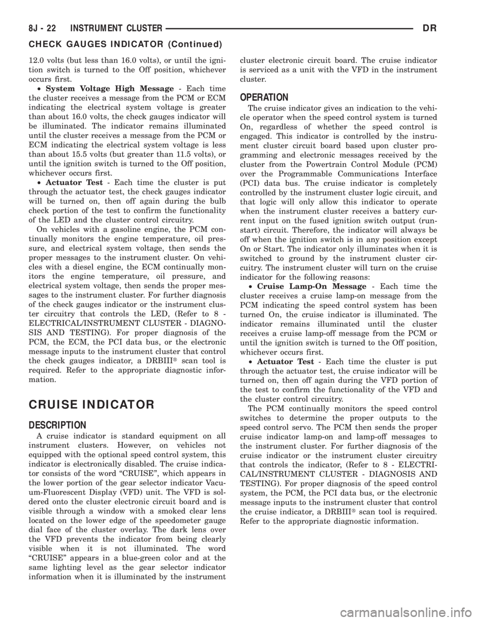
12.0 volts (but less than 16.0 volts), or until the igni-
tion switch is turned to the Off position, whichever
occurs first.
²System Voltage High Message- Each time
the cluster receives a message from the PCM or ECM
indicating the electrical system voltage is greater
than about 16.0 volts, the check gauges indicator will
be illuminated. The indicator remains illuminated
until the cluster receives a message from the PCM or
ECM indicating the electrical system voltage is less
than about 15.5 volts (but greater than 11.5 volts), or
until the ignition switch is turned to the Off position,
whichever occurs first.
²Actuator Test- Each time the cluster is put
through the actuator test, the check gauges indicator
will be turned on, then off again during the bulb
check portion of the test to confirm the functionality
of the LED and the cluster control circuitry.
On vehicles with a gasoline engine, the PCM con-
tinually monitors the engine temperature, oil pres-
sure, and electrical system voltage, then sends the
proper messages to the instrument cluster. On vehi-
cles with a diesel engine, the ECM continually mon-
itors the engine temperature, oil pressure, and
electrical system voltage, then sends the proper mes-
sages to the instrument cluster. For further diagnosis
of the check gauges indicator or the instrument clus-
ter circuitry that controls the LED, (Refer to 8 -
ELECTRICAL/INSTRUMENT CLUSTER - DIAGNO-
SIS AND TESTING). For proper diagnosis of the
PCM, the ECM, the PCI data bus, or the electronic
message inputs to the instrument cluster that control
the check gauges indicator, a DRBIIItscan tool is
required. Refer to the appropriate diagnostic infor-
mation.
CRUISE INDICATOR
DESCRIPTION
A cruise indicator is standard equipment on all
instrument clusters. However, on vehicles not
equipped with the optional speed control system, this
indicator is electronically disabled. The cruise indica-
tor consists of the word ªCRUISEº, which appears in
the lower portion of the gear selector indicator Vacu-
um-Fluorescent Display (VFD) unit. The VFD is sol-
dered onto the cluster electronic circuit board and is
visible through a window with a smoked clear lens
located on the lower edge of the speedometer gauge
dial face of the cluster overlay. The dark lens over
the VFD prevents the indicator from being clearly
visible when it is not illuminated. The word
ªCRUISEº appears in a blue-green color and at the
same lighting level as the gear selector indicator
information when it is illuminated by the instrumentcluster electronic circuit board. The cruise indicator
is serviced as a unit with the VFD in the instrument
cluster.
OPERATION
The cruise indicator gives an indication to the vehi-
cle operator when the speed control system is turned
On, regardless of whether the speed control is
engaged. This indicator is controlled by the instru-
ment cluster circuit board based upon cluster pro-
gramming and electronic messages received by the
cluster from the Powertrain Control Module (PCM)
over the Programmable Communications Interface
(PCI) data bus. The cruise indicator is completely
controlled by the instrument cluster logic circuit, and
that logic will only allow this indicator to operate
when the instrument cluster receives a battery cur-
rent input on the fused ignition switch output (run-
start) circuit. Therefore, the indicator will always be
off when the ignition switch is in any position except
On or Start. The indicator only illuminates when it is
switched to ground by the instrument cluster cir-
cuitry. The instrument cluster will turn on the cruise
indicator for the following reasons:
²Cruise Lamp-On Message- Each time the
cluster receives a cruise lamp-on message from the
PCM indicating the speed control system has been
turned On, the cruise indicator is illuminated. The
indicator remains illuminated until the cluster
receives a cruise lamp-off message from the PCM or
until the ignition switch is turned to the Off position,
whichever occurs first.
²Actuator Test- Each time the cluster is put
through the actuator test, the cruise indicator will be
turned on, then off again during the VFD portion of
the test to confirm the functionality of the VFD and
the cluster control circuitry.
The PCM continually monitors the speed control
switches to determine the proper outputs to the
speed control servo. The PCM then sends the proper
cruise indicator lamp-on and lamp-off messages to
the instrument cluster. For further diagnosis of the
cruise indicator or the instrument cluster circuitry
that controls the indicator, (Refer to 8 - ELECTRI-
CAL/INSTRUMENT CLUSTER - DIAGNOSIS AND
TESTING). For proper diagnosis of the speed control
system, the PCM, the PCI data bus, or the electronic
message inputs to the instrument cluster that control
the cruise indicator, a DRBIIItscan tool is required.
Refer to the appropriate diagnostic information.
8J - 22 INSTRUMENT CLUSTERDR
CHECK GAUGES INDICATOR (Continued)
Page 2872 of 2895
HIGH-PRESSURE FUEL LINE LEAKS -
DIAGNOSIS AND TESTING.............14-69
HINGE - INSTALLATION.....23-16,23-22,23-31,
23-46
HINGE - INSTALLATION, CENTER SEAT
BACK..............................23-80
HINGE - REMOVAL....23-16,23-22,23-31,23-46
HINGE - REMOVAL, CENTER SEAT BACK . . 23-79
HINGE COVER - INSTALLATION, CENTER
SEAT BACK INERTIA..................23-78
HINGE COVER - REMOVAL, CENTER
SEAT BACK INERTIA..................23-78
HITCH - INSTALLATION, TRAILER........13-25
HITCH - REMOVAL, TRAILER...........13-25
HOAT COOLANT - DESCRIPTION..........7-37
HOISTING - STANDARD PROCEDURE......0-14
HOLDDOWN - DESCRIPTION, BATTERY . . . 8F-14
HOLDDOWN - INSTALLATION, BATTERY . . . 8F-14
HOLDDOWN - OPERATION, BATTERY.....8F-14
HOLDDOWN - REMOVAL, BATTERY......8F-14
HOLDER - INSTALLATION, CUP.........23-52
HOLDER - REMOVAL, CUP.............23-52
HOLDING CLUTCHES - DESCRIPTION....21-546
HOLDING CLUTCHES - OPERATION.....21-546
HOLE PLUG - INSTALLATION, CAMSHAFT
CORE..............................9-201
HOLE PLUG - REMOVAL, CAMSHAFT
CORE..............................9-200
HOLE REPAIR - DESCRIPTION,
THREADED........................Intro.-9
HONING - STANDARD PROCEDURE,
CYLINDER BORE.......9-126,9-233,9-360,9-37
HOOD - INSTALLATION................23-47
HOOD - REMOVAL....................23-47
HOOK - INSTALLATION, COAT...........23-67
HOOK - REMOVAL, COAT..............23-67
HOOK ASSEMBLY - INSTALLATION,
FRONT TOW........................13-26
HOOK ASSEMBLY - REMOVAL, FRONT
TOW ..............................13-26
HORN - DIAGNOSIS AND TESTING.......8H-1
HORN - INSTALLATION.................8H-2
HORN - REMOVAL....................8H-2
HORN SWITCH - DESCRIPTION..........8H-2
HORN SWITCH - DIAGNOSIS AND
TESTING............................8H-2
HORN SYSTEM - DESCRIPTION..........8H-1
HORN SYSTEM - DIAGNOSIS AND
TESTING............................8H-1
HORN SYSTEM - OPERATION............8H-1
HOSE - GEAR TO COOLER -
INSTALLATION, RETURN..........19-43,19-44
HOSE - GEAR TO COOLER - REMOVAL,
RETURN............................19-43
HOSE - INSTALLATION, FRONT BRAKE......5-9
HOSE - INSTALLATION, PRESSURE . 19-43,19-44
HOSE - INSTALLATION, REAR BRAKE.......5-9
HOSE - REMOVAL, FRONT...............5-9
HOSE - REMOVAL, PRESSURE.....19-43,19-44
HOSE - REMOVAL, REAR BRAKE..........5-8
HOSE - RESERVOIR TO COOLER -
INSTALLATION, RETURN..........19-43,19-44
HOSE - RESERVOIR TO COOLER -
REMOVAL, RETURN.............19-43,19-44
HOSE ASSEMBLY - INSTALLATION, REAR
TUBE................................5-9
HOSE ASSEMBLY - REMOVAL, REAR
TUBE................................5-8
HOSE CLAMPS - DESCRIPTION...........7-3
HOSE CLAMPS - OPERATION.............7-5
HOSE WITH AIR CONDITIONING -
INSTALLATION, WATER PUMP BYPASS....7-70
HOSE WITH AIR CONDITIONING -
REMOVAL, WATER PUMP BYPASS........7-68
HOSE WITHOUT AIR CONDITIONING -
INSTALLATION, WATER PUMP BYPASS....7-70
HOSE WITHOUT AIR CONDITIONING -
REMOVAL, WATER PUMP BYPASS........7-69
HOSES/LINES/TUBES PRECAUTIONS -
CAUTION, REFRIGERANT..............24-33
HOSES/TUBES - DESCRIPTION, WASHER . 8R-11
HOSES/TUBES - OPERATION, WASHER . . . 8R-11
HOUSING - ASSEMBLY, HVAC
...........24-28
HOUSING - DIAGNOSIS AND TESTING,
CLUTCH
..............................6-8
HOUSING - DISASSEMBLY, HVAC
........24-28
HOUSING - INSTALLATION, CLUTCH
......6-10
HOUSING - INSTALLATION, GEAR
........9-349HOUSING - INSTALLATION, HVAC........24-29
HOUSING - INSTALLATION, ROCKER.....9-304
HOUSING - REMOVAL, CLUTCH..........6-10
HOUSING - REMOVAL, GEAR...........9-348
HOUSING - REMOVAL, HVAC...........24-27
HOUSING - REMOVAL, ROCKER.........9-304
HOUSING BUSHING - INSTALLATION,
EXTENSION........................21-200
HOUSING BUSHING - REMOVAL,
EXTENSION........................21-200
HOUSING BUSHING AND SEAL -
INSTALLATION, EXTENSION.....21-616,21-682
HOUSING BUSHING AND SEAL -
REMOVAL, EXTENSION.........21-616,21-682
HOUSING COVER - INSTALLATION, GEAR . 9-350
HOUSING COVER - REMOVAL, GEAR.....9-349
HOUSING FLUID LEAK - DIAGNOSIS AND
TESTING, CONVERTER . . . 21-143,21-324,21-495
HOUSING SEAL - INSTALLATION,
ADAPTER...............21-127,21-539,21-83
HOUSING SEAL - INSTALLATION,
EXTENSION.......21-127,21-200,21-380,21-83
HOUSING SEAL - REMOVAL, ADAPTER . . 21-127,
21-539,21-83
HOUSING SEAL - REMOVAL,
EXTENSION.......21-127,21-200,21-380,21-83
HOUSING SEAL AND DUST BOOT -
INSTALLATION, EXTENSION.....21-652,21-716
HOUSING SEAL AND DUST BOOT -
REMOVAL, EXTENSION.........21-652,21-716
HOW TO USE WIRING DIAGRAMS -
DESCRIPTION.....................8W-01-1
H-SECTION REPLACEMENT - STANDARD
PROCEDURE, REAR FRAME............13-15
HUB / BEARING - INSTALLATION.........2-31
HUB / BEARING - REMOVAL.............2-30
HVAC HOUSING - ASSEMBLY...........24-28
HVAC HOUSING - DISASSEMBLY........24-28
HVAC HOUSING - INSTALLATION........24-29
HVAC HOUSING - REMOVAL............24-27
HYDRAULIC BOOSTER - DIAGNOSIS
AND TESTING........................5-25
HYDRAULIC LASH ADJUSTER -
DIAGNOSIS AND TESTING.........9-124,9-31
HYDRAULIC LIFTERS - CLEANING . . 9-260,9-388
HYDRAULIC LIFTERS - INSTALLATION . . . 9-260,
9-388
HYDRAULIC LIFTERS - REMOVAL . . . 9-259,9-387
HYDRAULIC PRESSURE TEST -
DIAGNOSIS AND TESTING......21-140,21-321,
21-493
HYDRAULIC SCHEMATICS, SCHEMATICS
AND DIAGRAMS........21-175,21-355,21-513
HYDRAULIC TAPPETS - DIAGNOSIS AND
TESTING......................9-258,9-386
HYDROBOOST - INSTALLATION..........5-22
HYDROBOOST - INSTALLATION, ALL
EXCEPT.............................5-22
HYDROBOOST - REMOVAL..............5-21
HYDROBOOST - REMOVAL, ALL EXCEPT . . . 5-21
HYDRO-BOOST BRAKE BOOSTER -
INSTALLATION........................5-27
HYDRO-BOOST BRAKE BOOSTER -
REMOVAL...........................5-27
HYDROFORM FENDER RAIL REPAIR -
STANDARD PROCEDURE...............13-12
HYDROSTATIC LOCK - STANDARD
PROCEDURE.........9-186,9-232,9-290,9-361
IDENTIFICATION - DESCRIPTION,
FASTENER.........................Intro.-6
IDENTIFICATION AND INFORMATION -
DESCRIPTION, SECTION.............8W-01-6
IDENTIFICATION NUMBER -
DESCRIPTION, VEHICLE..............Intro.-2
IDLE AIR CONTROL MOTOR -
DESCRIPTION.......................14-33
IDLE AIR CONTROL MOTOR -
INSTALLATION.......................14-35
IDLE AIR CONTROL MOTOR -
OPERATION.........................14-33
IDLE AIR CONTROL MOTOR - REMOVAL . . 14-34
IDLER SHAFT - INSTALLATION......9-175,9-80
IDLER SHAFT - REMOVAL
..........9-175,9-79
IGNITION - SPECIFICATIONS, TORQUE
.....8I-3
IGNITION CIRCUIT SENSE -
DESCRIPTION
.......................8E-10
IGNITION CIRCUIT SENSE - OPERATION
. . 8E-12
IGNITION COIL - DESCRIPTION
..........8I-19IGNITION COIL - INSTALLATION.........8I-24
IGNITION COIL - OPERATION............8I-20
IGNITION COIL - REMOVAL.............8I-23
IGNITION COIL CAPACITOR -
DESCRIPTION........................8I-33
IGNITION COIL CAPACITOR -
INSTALLATION.......................8I-33
IGNITION COIL CAPACITOR - OPERATION . . 8I-33
IGNITION COIL CAPACITOR - REMOVAL . . . 8I-33
IGNITION COIL RESISTANCE, 3.7L V-6.....8I-6
IGNITION COIL RESISTANCE, 4.7L V-8.....8I-6
IGNITION COIL RESISTANCE, 5.7L V-8.....8I-6
IGNITION COIL RESISTANCE, 5.9L.........8I-6
IGNITION COIL RESISTANCE, 8.0L V-10
ENGINE..............................8I-6
IGNITION CONTROL - DESCRIPTION.......8I-1
IGNITION SWITCH - DESCRIPTION........19-9
IGNITION SWITCH - DESCRIPTION,
KEY-IN.............................19-11
IGNITION SWITCH - DIAGNOSIS AND
TESTING............................19-9
IGNITION SWITCH - INSTALLATION......19-11
IGNITION SWITCH - OPERATION.........19-9
IGNITION SWITCH - REMOVAL..........19-10
IGNITION SWITCH AND KEY LOCK
CYLINDER - DIAGNOSIS AND TESTING . . . 19-11
IGNITION TIMING, SPECIFICATIONS.......8I-6
IGNITION-OFF DRAW TEST - STANDARD
PROCEDURE..........................8F-11
IMMOBILIZER MODULE - DESCRIPTION,
SENTRY KEY........................8E-13
IMMOBILIZER MODULE - INSTALLATION,
SENTRY KEY........................8E-15
IMMOBILIZER MODULE - OPERATION,
SENTRY KEY........................8E-13
IMMOBILIZER MODULE - REMOVAL,
SENTRY KEY........................8E-15
IMMOBILIZER SYSTEM INDICATOR
LAMP - DESCRIPTION, SENTRY KEY......8Q-5
IMMOBILIZER SYSTEM INDICATOR
LAMP - OPERATION, SENTRY KEY........8Q-5
IMMOBILIZER SYSTEM INITIALIZATION,
STANDARD PROCEDURE - SENTRY
KEY................................8Q-3
IMMOBILIZER SYSTEM (SKIS),
DESCRIPTION - SENTRY KEY............8Q-1
IMMOBILIZER SYSTEM TRANSPONDER
PROGRAMMING, STANDARD
PROCEDURE - SENTRY KEY.............8Q-4
IMPACT AIRBAG CONTROL MODULE -
DESCRIPTION, SIDE..................8O-53
IMPACT AIRBAG CONTROL MODULE -
OPERATION, SIDE....................8O-54
INCORRECT FLUID LEVEL - DIAGNOSIS
AND TESTING, EFFECTS OF.....21-201,21-381,
21-541
INDEPENDENT FRONT SUSPENSION -
DESCRIPTION, GEAR..................19-16
INDEPENDENT FRONT SUSPENSION -
INSTALLATION, GEAR.................19-17
INDEPENDENT FRONT SUSPENSION -
REMOVAL, GEAR.....................19-16
INDICATOR - DESCRIPTION, ABS........8J-17
INDICATOR - DESCRIPTION, AIRBAG.....8J-18
INDICATOR - DESCRIPTION, BRAKE/
PARK BRAKE........................8J-18
INDICATOR - DESCRIPTION, CARGO
LAMP..............................8J-20
INDICATOR - DESCRIPTION, CHECK
GAUGES............................8J-21
INDICATOR - DESCRIPTION, CRUISE.....8J-22
INDICATOR - DESCRIPTION, DOOR AJAR . . 8J-23
INDICATOR - DESCRIPTION, ETC........8J-24
INDICATOR - DESCRIPTION, GEAR
SELECTOR..........................8J-26
INDICATOR - DESCRIPTION, HIGH BEAM . . 8J-27
INDICATOR - DESCRIPTION, LAMP OUT . . . 8J-28
INDICATOR - DESCRIPTION, LOW FUEL . . . 8J-29
INDICATOR - DESCRIPTION, OVERDRIVE
OFF ...............................8J-33
INDICATOR - DESCRIPTION, SEATBELT
. . . 8J-34
INDICATOR - DESCRIPTION, SECURITY
. . . 8J-34
INDICATOR - DESCRIPTION, SERVICE
4WD
...............................8J-35
INDICATOR - DESCRIPTION, TRANS
TEMP
..............................8J-38
INDICATOR - DESCRIPTION, TURN
SIGNAL
............................8J-39
DRINDEX 17
Description Group-Page Description Group-Page Description Group-Page