2003 CHRYSLER VOYAGER transmission oil
[x] Cancel search: transmission oilPage 1268 of 2177
INSTALLATION - ENGINE ASSEMBLY
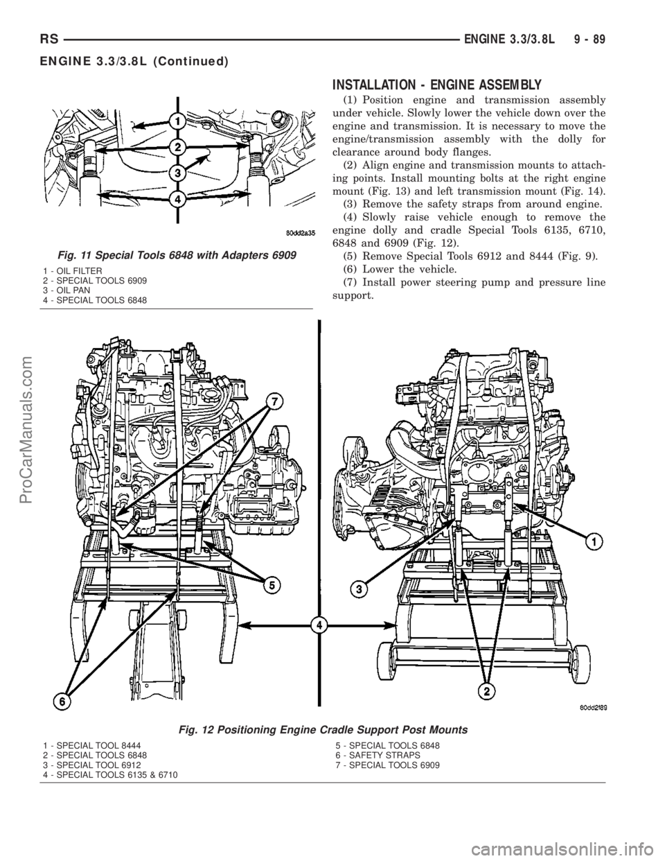
(1) Position engine and transmission assembly
under vehicle. Slowly lower the vehicle down over the
engine and transmission. It is necessary to move the
engine/transmission assembly with the dolly for
clearance around body flanges.
(2)
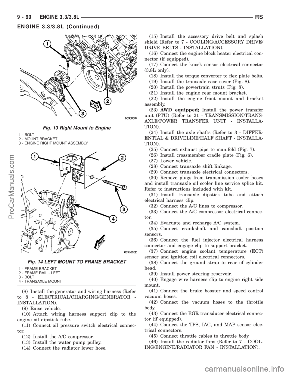
Align engine and transmission mounts to attach-
ing points. Install mounting bolts at the right engine
mount (Fig. 13) and left transmission mount (Fig. 14).
(3) Remove the safety straps from around engine.
(4) Slowly raise vehicle enough to remove the
engine dolly and cradle Special Tools 6135, 6710,
6848 and 6909 (Fig. 12).
(5) Remove Special Tools 6912 and 8444 (Fig. 9).
(6) Lower the vehicle.
(7) Install power steering pump and pressure line
support.
Fig. 11 Special Tools 6848 with Adapters 6909
1 - OIL FILTER
2 - SPECIAL TOOLS 6909
3 - OIL PAN
4 - SPECIAL TOOLS 6848
Fig. 12 Positioning Engine Cradle Support Post Mounts
1 - SPECIAL TOOL 8444
2 - SPECIAL TOOLS 6848
3 - SPECIAL TOOL 6912
4 - SPECIAL TOOLS 6135 & 67105 - SPECIAL TOOLS 6848
6 - SAFETY STRAPS
7 - SPECIAL TOOLS 6909
RSENGINE 3.3/3.8L9-89
ENGINE 3.3/3.8L (Continued)
ProCarManuals.com
Page 1269 of 2177
(8) Install the generator and wiring harness (Refer
to 8 - ELECTRICAL/CHARGING/GENERATOR -
INSTALLATION).
(9) Raise vehicle.
(10) Attach wiring harness support clip to the
engine oil dipstick tube.
(11) Connect oil pressure switch electrical connec-
tor.
(12) Install the A/C compressor.
(13) Install the water pump pulley.
(14) Connect the radiator lower hose.(15) Install the accessory drive belt and splash
shield (Refer to 7 - COOLING/ACCESSORY DRIVE/
DRIVE BELTS - INSTALLATION).
(16) Connect the engine block heater electrical con-
nector (if equipped).
(17) Connect the knock sensor electrical connector
(3.8L only).
(18) Install the torque converter to flex plate bolts.
(19) Install the transaxle case cover (Fig. 8).
(20) Install the powertrain struts (Fig. 8).
(21) Install the engine rear mount bracket.
(22) Install the engine front mount and bracket
assembly.
(23)AWD equipped;Install the power transfer
unit (PTU) (Refer to 21 - TRANSMISSION/TRANS-
AXLE/POWER TRANSFER UNIT - INSTALLA-
TION).
(24) Install the axle shafts (Refer to 3 - DIFFER-
ENTIAL & DRIVELINE/HALF SHAFT - INSTALLA-
TION).
(25) Connect exhaust pipe to manifold (Fig. 7).
(26) Install crossmember cradle plate (Fig. 6).
(27) Lower vehicle.
(28) Connect transaxle shift linkage.
(29) Connect transaxle electrical connectors.
(30) Remove plugs from transmission cooler hoses
and install transaxle oil cooler line service splice kit.
Refer to instructions included with kit.
(31) Install transaxle dipstick tube and attach
electrical harness clip.
(32) Connect the A/C lines to compressor.
(33) Connect the A/C compressor electrical connec-
tor.
(34) Evacuate and recharge A/C system.
(35) Connect crankshaft and camshaft position
sensors.
(36) Connect the fuel injector electrical harness
connector and engage clip to support bracket.
(37) Connect engine coolant temperature (ECT)
sensor and ignition coil electrical connectors.
(38) Connect the ground strap to rear of cylinder
head.
(39) Install power steering reservoir.
(40) Engage wire harness clip to engine right side
mount.
(41) Connect the brake booster and speed control
vacuum hoses.
(42) Connect the vacuum hoses to the throttle
body.
(43) Connect the EGR transducer electrical connec-
tor (if equipped).
(44) Connect the TPS, IAC, and MAP sensor elec-
trical connectors.
(45) Connect throttle cables to throttle body.
(46) Install the radiator fans (Refer to 7 - COOL-
ING/ENGINE/RADIATOR FAN - INSTALLATION).
Fig. 13 Right Mount to Engine
1 - BOLT
2 - MOUNT BRACKET
3 - ENGINE RIGHT MOUNT ASSEMBLY
Fig. 14 LEFT MOUNT TO FRAME BRACKET
1 - FRAME BRACKET
2 - FRAME RAIL - LEFT
3 - BOLT
4 - TRANSAXLE MOUNT
9 - 90 ENGINE 3.3/3.8LRS
ENGINE 3.3/3.8L (Continued)
ProCarManuals.com
Page 1270 of 2177
(47) Connect the radiator upper hose.
(48) Connect the heater hoses. Remove pinch-off
pliers from the rear heater hoses (if equipped).
(49) Install the radiator upper support crossmem-
ber (Refer to 23 - BODY/EXTERIOR/GRILLE OPEN-
ING REINFORCEMENT - INSTALLATION).
(50) Install the wiper module (Refer to 8 - ELEC-
TRICAL/WIPERS/WASHERS/WIPER MODULE -
INSTALLATION).
(51) Connect the fuel line to fuel rail (Refer to 14 -
FUEL SYSTEM/FUEL DELIVERY/FUEL LINES -
STANDARD PROCEDURE).
(52) Install the air cleaner and hoses.
(53) Install new oil filter. Fill engine crankcase
with proper oil to correct level.
(54) Connect negative cable to battery.
(55) Fill the cooling system (Refer to 7 - COOLING
- STANDARD PROCEDURE).
(56) Start engine and run until operating temper-
ature is reached.
(57) Adjust transmission linkage, if necessary.
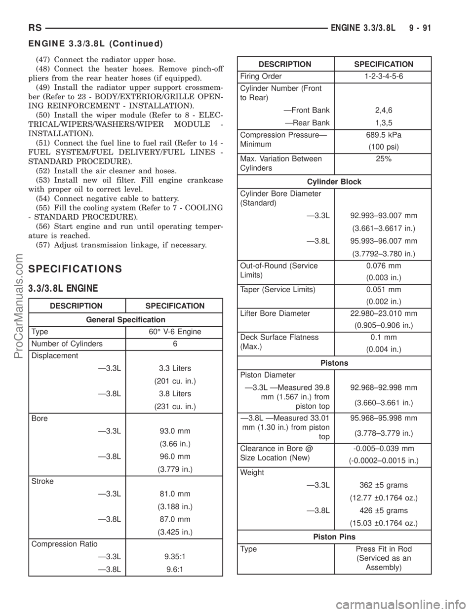
SPECIFICATIONS
3.3/3.8L ENGINE
DESCRIPTION SPECIFICATION
General Specification
Type 60É V-6 Engine
Number of Cylinders 6
Displacement
Ð3.3L 3.3 Liters
(201 cu. in.)
Ð3.8L 3.8 Liters
(231 cu. in.)
Bore
Ð3.3L 93.0 mm
(3.66 in.)
Ð3.8L 96.0 mm
(3.779 in.)
Stroke
Ð3.3L 81.0 mm
(3.188 in.)
Ð3.8L 87.0 mm
(3.425 in.)
Compression Ratio
Ð3.3L 9.35:1
Ð3.8L 9.6:1
DESCRIPTION SPECIFICATION
Firing Order 1-2-3-4-5-6
Cylinder Number (Front
to Rear)
ÐFront Bank 2,4,6
ÐRear Bank 1,3,5
Compression PressureÐ
Minimum689.5 kPa
(100 psi)
Max. Variation Between
Cylinders25%
Cylinder Block
Cylinder Bore Diameter
(Standard)
Ð3.3L 92.993±93.007 mm
(3.661±3.6617 in.)
Ð3.8L 95.993±96.007 mm
(3.7792±3.780 in.)
Out-of-Round (Service
Limits)0.076 mm
(0.003 in.)
Taper (Service Limits) 0.051 mm
(0.002 in.)
Lifter Bore Diameter 22.980±23.010 mm
(0.905±0.906 in.)
Deck Surface Flatness
(Max.)0.1 mm
(0.004 in.)
Pistons
Piston Diameter
Ð3.3L ÐMeasured 39.8
mm (1.567 in.) from
piston top92.968±92.998 mm
(3.660±3.661 in.)
Ð3.8L ÐMeasured 33.01
mm (1.30 in.) from piston
top95.968±95.998 mm
(3.778±3.779 in.)
Clearance in Bore @
Size Location (New)-0.005±0.039 mm
(-0.0002±0.0015 in.)
Weight
Ð3.3L 362 5 grams
(12.77 0.1764 oz.)
Ð3.8L 426 5 grams
(15.03 0.1764 oz.)
Piston Pins
Type Press Fit in Rod
(Serviced as an
Assembly)
RSENGINE 3.3/3.8L9-91
ENGINE 3.3/3.8L (Continued)
ProCarManuals.com
Page 1291 of 2177
REMOVAL
(1) Remove the valve springs. (Refer to 9 -
ENGINE/CYLINDER HEAD/VALVE SPRINGS -
REMOVAL)
(2) Remove the valve stem seal (Fig. 43).
INSTALLATION
(1) Install the valve stem seal squarely over the
valve guide, using the valve stem as a guide (Fig.
43). Do not force the seal against top of the valve
guide.
(2) Install the valve spring. (Refer to 9 - ENGINE/
CYLINDER HEAD/VALVE SPRINGS - INSTALLA-
TION)
ENGINE BLOCK
DESCRIPTION
The cylinder block is made of cast iron and is a
deep skirt design.
STANDARD PROCEDURE - CYLINDER BORE
HONING
(1) Used carefully, the cylinder bore resizing hone,
recommended tool C-823 or equivalent, equipped
with 220 grit stones, is the best tool for this honing
procedure. In addition to deglazing, it will reduce
taper and out-of-round as well as removing light
scuffing, scoring or scratches. Usually a few strokes
will clean up a bore and maintain the required lim-
its.
(2) Deglazing of the cylinder walls may be done
using a cylinder surfacing hone, recommended tool
C-3501 or equivalent, equipped with 280 grit stones,
if the cylinder bore is straight and round. 20±60
strokes depending on the bore condition, will be suf-
ficient to provide a satisfactory surface. Use a light
honing oil.Do not use engine or transmission oil,
mineral spirits or kerosene.Inspect cylinder walls
after each 20 strokes.
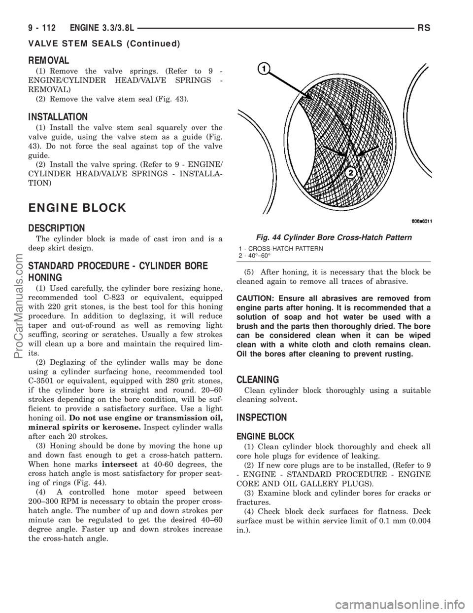
(3) Honing should be done by moving the hone up
and down fast enough to get a cross-hatch pattern.
When hone marksintersectat 40-60 degrees, the
cross hatch angle is most satisfactory for proper seat-
ing of rings (Fig. 44).
(4) A controlled hone motor speed between
200±300 RPM is necessary to obtain the proper cross-
hatch angle. The number of up and down strokes per
minute can be regulated to get the desired 40±60
degree angle. Faster up and down strokes increase
the cross-hatch angle.(5) After honing, it is necessary that the block be
cleaned again to remove all traces of abrasive.
CAUTION: Ensure all abrasives are removed from
engine parts after honing. It is recommended that a
solution of soap and hot water be used with a
brush and the parts then thoroughly dried. The bore
can be considered clean when it can be wiped
clean with a white cloth and cloth remains clean.
Oil the bores after cleaning to prevent rusting.
CLEANING
Clean cylinder block thoroughly using a suitable
cleaning solvent.
INSPECTION
ENGINE BLOCK
(1) Clean cylinder block thoroughly and check all
core hole plugs for evidence of leaking.
(2) If new core plugs are to be installed, (Refer to 9
- ENGINE - STANDARD PROCEDURE - ENGINE
CORE AND OIL GALLERY PLUGS).
(3) Examine block and cylinder bores for cracks or
fractures.
(4) Check block deck surfaces for flatness. Deck
surface must be within service limit of 0.1 mm (0.004
in.).
Fig. 44 Cylinder Bore Cross-Hatch Pattern
1 - CROSS-HATCH PATTERN
2 - 40ɱ60É
9 - 112 ENGINE 3.3/3.8LRS
VALVE STEM SEALS (Continued)
ProCarManuals.com
Page 1370 of 2177
REMOVAL
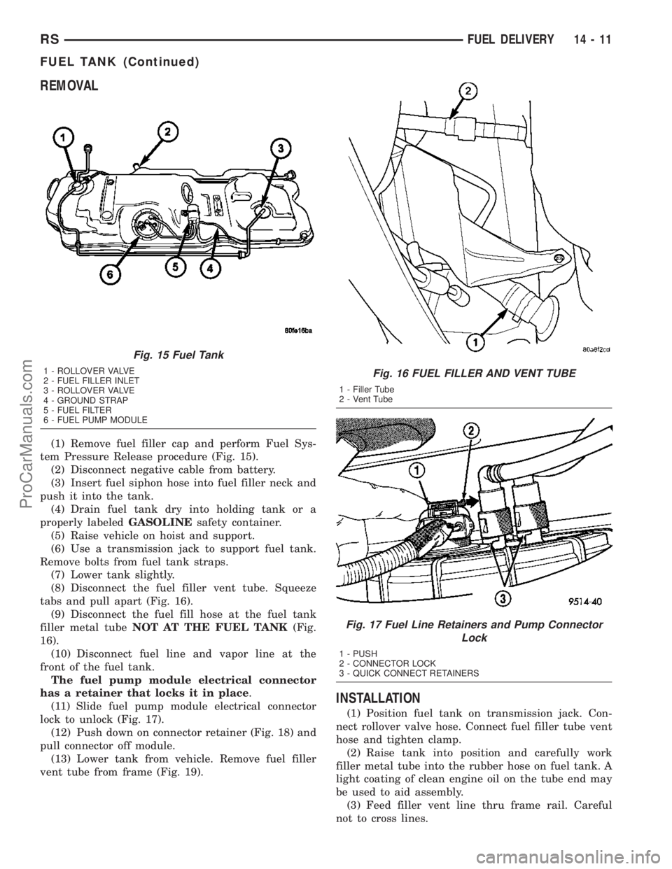
(1) Remove fuel filler cap and perform Fuel Sys-
tem Pressure Release procedure (Fig. 15).
(2) Disconnect negative cable from battery.
(3) Insert fuel siphon hose into fuel filler neck and
push it into the tank.
(4) Drain fuel tank dry into holding tank or a
properly labeledGASOLINEsafety container.
(5) Raise vehicle on hoist and support.
(6) Use a transmission jack to support fuel tank.
Remove bolts from fuel tank straps.
(7) Lower tank slightly.
(8) Disconnect the fuel filler vent tube. Squeeze
tabs and pull apart (Fig. 16).
(9) Disconnect the fuel fill hose at the fuel tank
filler metal tubeNOT AT THE FUEL TANK(Fig.
16).
(10) Disconnect fuel line and vapor line at the
front of the fuel tank.
The fuel pump module electrical connector
has a retainer that locks it in place.
(11) Slide fuel pump module electrical connector
lock to unlock (Fig. 17).
(12) Push down on connector retainer (Fig. 18) and
pull connector off module.
(13) Lower tank from vehicle. Remove fuel filler
vent tube from frame (Fig. 19).
INSTALLATION
(1) Position fuel tank on transmission jack. Con-
nect rollover valve hose. Connect fuel filler tube vent
hose and tighten clamp.
(2) Raise tank into position and carefully work
filler metal tube into the rubber hose on fuel tank. A
light coating of clean engine oil on the tube end may
be used to aid assembly.
(3) Feed filler vent line thru frame rail. Careful
not to cross lines.
Fig. 15 Fuel Tank
1 - ROLLOVER VALVE
2 - FUEL FILLER INLET
3 - ROLLOVER VALVE
4 - GROUND STRAP
5 - FUEL FILTER
6 - FUEL PUMP MODULEFig. 16 FUEL FILLER AND VENT TUBE
1 - Filler Tube
2 - Vent Tube
Fig. 17 Fuel Line Retainers and Pump Connector
Lock
1 - PUSH
2 - CONNECTOR LOCK
3 - QUICK CONNECT RETAINERS
RSFUEL DELIVERY14-11
FUEL TANK (Continued)
ProCarManuals.com
Page 1371 of 2177
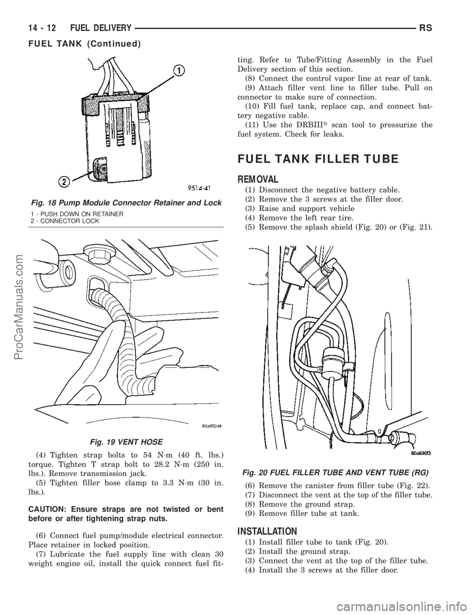
(4) Tighten strap bolts to 54 N´m (40 ft. lbs.)
torque. Tighten T strap bolt to 28.2 N´m (250 in.
lbs.). Remove transmission jack.
(5) Tighten filler hose clamp to 3.3 N´m (30 in.
lbs.).
CAUTION: Ensure straps are not twisted or bent
before or after tightening strap nuts.
(6) Connect fuel pump/module electrical connector.
Place retainer in locked position.
(7) Lubricate the fuel supply line with clean 30
weight engine oil, install the quick connect fuel fit-ting. Refer to Tube/Fitting Assembly in the Fuel
Delivery section of this section.
(8) Connect the control vapor line at rear of tank.
(9) Attach filler vent line to filler tube. Pull on
connector to make sure of connection.
(10) Fill fuel tank, replace cap, and connect bat-
tery negative cable.
(11) Use the DRBIIItscan tool to pressurize the
fuel system. Check for leaks.
FUEL TANK FILLER TUBE
REMOVAL
(1) Disconnect the negative battery cable.
(2) Remove the 3 screws at the filler door.
(3) Raise and support vehicle
(4) Remove the left rear tire.
(5) Remove the splash shield (Fig. 20) or (Fig. 21).
(6) Remove the canister from filler tube (Fig. 22).
(7) Disconnect the vent at the top of the filler tube.
(8) Remove the ground strap.
(9) Remove filler tube at tank.
INSTALLATION
(1) Install filler tube to tank (Fig. 20).
(2) Install the ground strap.
(3) Connect the vent at the top of the filler tube.
(4) Install the 3 screws at the filler door.
Fig. 18 Pump Module Connector Retainer and Lock
1 - PUSH DOWN ON RETAINER
2 - CONNECTOR LOCK
Fig. 19 VENT HOSE
Fig. 20 FUEL FILLER TUBE AND VENT TUBE (RG)
14 - 12 FUEL DELIVERYRS
FUEL TANK (Continued)
ProCarManuals.com
Page 1448 of 2177
TRANSMISSION/TRANSAXLE
TABLE OF CONTENTS
page page
POWER TRANSFER UNIT..................1
T850 MANUAL TRANSAXLE...............2141TE AUTOMATIC TRANSAXLE............116
POWER TRANSFER UNIT
TABLE OF CONTENTS
page page
POWER TRANSFER UNIT
DESCRIPTION..........................1
OPERATION............................3
DIAGNOSIS AND TESTING
SEAL IDENTIFICATION..................3
FLUID LEAK DIAGNOSIS................3
STANDARD PROCEDURE
STANDARD PROCEDURE - FLUID LEVEL
INSPECTION..........................4
STANDARD PROCEDURE - PTU FLUID
CHANGE.............................5
REMOVAL.............................5
INSTALLATION..........................6
ADJUSTMENTS
OUTPUT FLANGE SHIM SELECTION.......7
SPECIFICATIONS
TORQUE.............................7
SPECIAL TOOLS
SDP POWER TRANSFER UNIT............8
DIFFERENTIAL CARRIER SEAL
REMOVAL.............................9
INSTALLATION..........................9
END COVER BALL BEARING
REMOVAL.............................9INSTALLATION.........................10
END COVER SEAL
REMOVAL.............................11
INSTALLATION.........................11
HALF SHAFT INNER SEAL
REMOVAL.............................12
INSTALLATION.........................12
INPUT SHAFT COVER SEAL
REMOVAL.............................13
INSTALLATION.........................14
INPUT SHAFT END SEAL
REMOVAL.............................15
INSTALLATION.........................16
INPUT SHAFT SEAL
REMOVAL.............................17
INSTALLATION.........................18
OUTER HALF SHAFT SEAL
REMOVAL.............................19
INSTALLATION.........................19
REAR COVER O-RING
REMOVAL.............................19
INSTALLATION.........................20
POWER TRANSFER UNIT
DESCRIPTION
The Power Transfer Unit (P.T.U.) is attached to a
modified automatic transaxle case where the right
half shaft extension housing would normally be
located.
The Power Transfer Unit is sealed from the trans-
axle and has its own oil sump. The Unit uses MopartSAE 80W-90 Gear and Axle Lubricant (MS-9020) and
holds 1.15 liters (1.22 quarts).
Service of the Power Transfer Unit is limited to:
²Fluid Change
²Seals
²Gaskets
²One ball bearing
²Output flange
If the ring gear and pinion, any tapered roller
bearings, case, covers, or pinion carrier fail the entire
unit must be replaced.
RSTRANSMISSION/TRANSAXLE21-1
ProCarManuals.com
Page 1450 of 2177
OPERATION
The Transfer Unit provides the power to the rear
wheels through a hypoid ring gear and pinion set.
DIAGNOSIS AND TESTING
SEAL IDENTIFICATION
For accurate seal diagnosis, repair seal name and
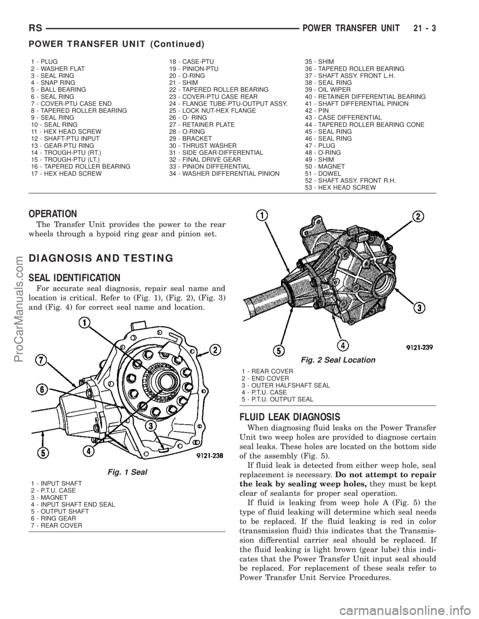
location is critical. Refer to (Fig. 1), (Fig. 2), (Fig. 3)
and (Fig. 4) for correct seal name and location.
FLUID LEAK DIAGNOSIS
When diagnosing fluid leaks on the Power Transfer
Unit two weep holes are provided to diagnose certain
seal leaks. These holes are located on the bottom side
of the assembly (Fig. 5).
If fluid leak is detected from either weep hole, seal
replacement is necessary.Do not attempt to repair
the leak by sealing weep holes,they must be kept
clear of sealants for proper seal operation.
If fluid is leaking from weep hole A (Fig. 5) the
type of fluid leaking will determine which seal needs
to be replaced. If the fluid leaking is red in color
(transmission fluid) this indicates that the Transmis-
sion differential carrier seal should be replaced. If
the fluid leaking is light brown (gear lube) this indi-
cates that the Power Transfer Unit input seal should
be replaced. For replacement of these seals refer to
Power Transfer Unit Service Procedures.
1 - PLUG 18 - CASE-PTU 35 - SHIM
2 - WASHER FLAT 19 - PINION-PTU 36 - TAPERED ROLLER BEARING
3 - SEAL RING 20 - O-RING 37 - SHAFT ASSY. FRONT L.H.
4 - SNAP RING 21 - SHIM 38 - SEAL RING
5 - BALL BEARING 22 - TAPERED ROLLER BEARING 39 - OIL WIPER
6 - SEAL RING 23 - COVER-PTU CASE REAR 40 - RETAINER DIFFERENTIAL BEARING
7 - COVER-PTU CASE END 24 - FLANGE TUBE-PTU-OUTPUT ASSY. 41 - SHAFT DIFFERENTIAL PINION
8 - TAPERED ROLLER BEARING 25 - LOCK NUT-HEX FLANGE 42 - PIN
9 - SEAL RING 26 - O- RING 43 - CASE DIFFERENTIAL
10 - SEAL RING 27 - RETAINER PLATE 44 - TAPERED ROLLER BEARING CONE
11 - HEX HEAD SCREW 28 - O-RING 45 - SEAL RING
12 - SHAFT-PTU INPUT 29 - BRACKET 46 - SEAL RING
13 - GEAR-PTU RING 30 - THRUST WASHER 47 - PLUG
14 - TROUGH-PTU (RT.) 31 - SIDE GEAR-DIFFERENTIAL 48 - O-RING
15 - TROUGH-PTU (LT.) 32 - FINAL DRIVE GEAR 49 - SHIM
16 - TAPERED ROLLER BEARING 33 - PINION DIFFERENTIAL 50 - MAGNET
17 - HEX HEAD SCREW 34 - WASHER DIFFERENTIAL PINION 51 - DOWEL
52 - SHAFT ASSY. FRONT R.H.
53 - HEX HEAD SCREW
Fig. 1 Seal
1 - INPUT SHAFT
2 - P.T.U. CASE
3 - MAGNET
4 - INPUT SHAFT END SEAL
5 - OUTPUT SHAFT
6 - RING GEAR
7 - REAR COVER
Fig. 2 Seal Location
1 - REAR COVER
2 - END COVER
3 - OUTER HALFSHAFT SEAL
4 - P.T.U. CASE
5 - P.T.U. OUTPUT SEAL
RSPOWER TRANSFER UNIT21-3
POWER TRANSFER UNIT (Continued)
ProCarManuals.com