2003 CHRYSLER VOYAGER transmission oil
[x] Cancel search: transmission oilPage 1696 of 2177
Since there are four switches, there are 16 possible
combinations of open and closed switches (codes).
Seven of these codes are related to gear position and
three are recognized as ªbetween gearº codes. This
results in six codes which should never occur. These
are called ªinvalidº codes. An invalid code will result
in a DTC, and the PCM/TCM will then determine the
shift lever position based on pressure switch data.
This allows reasonably normal transmission opera-
tion with a TRS failure.
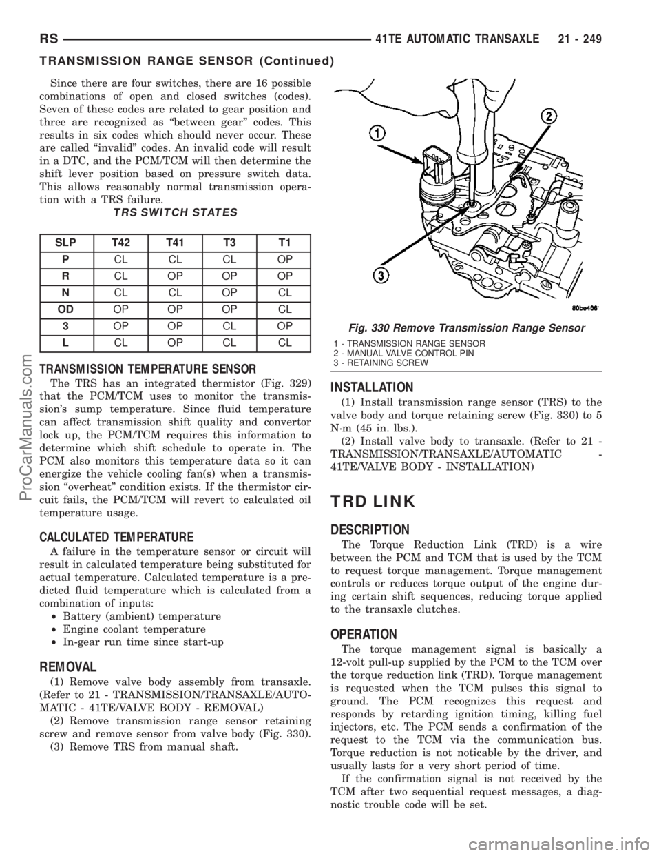
TRS SWITCH STATES
SLP T42 T41 T3 T1
PCL CL CL OP
RCL OP OP OP
NCL CL OP CL
ODOP OP OP CL
3OP OP CL OP
LCL OP CL CL
TRANSMISSION TEMPERATURE SENSOR
The TRS has an integrated thermistor (Fig. 329)
that the PCM/TCM uses to monitor the transmis-
sion's sump temperature. Since fluid temperature
can affect transmission shift quality and convertor
lock up, the PCM/TCM requires this information to
determine which shift schedule to operate in. The
PCM also monitors this temperature data so it can
energize the vehicle cooling fan(s) when a transmis-
sion ªoverheatº condition exists. If the thermistor cir-
cuit fails, the PCM/TCM will revert to calculated oil
temperature usage.
CALCULATED TEMPERATURE
A failure in the temperature sensor or circuit will
result in calculated temperature being substituted for
actual temperature. Calculated temperature is a pre-
dicted fluid temperature which is calculated from a
combination of inputs:
²Battery (ambient) temperature
²Engine coolant temperature
²In-gear run time since start-up
REMOVAL
(1) Remove valve body assembly from transaxle.
(Refer to 21 - TRANSMISSION/TRANSAXLE/AUTO-
MATIC - 41TE/VALVE BODY - REMOVAL)
(2) Remove transmission range sensor retaining
screw and remove sensor from valve body (Fig. 330).
(3) Remove TRS from manual shaft.
INSTALLATION
(1) Install transmission range sensor (TRS) to the
valve body and torque retaining screw (Fig. 330) to 5
N´m (45 in. lbs.).
(2) Install valve body to transaxle. (Refer to 21 -
TRANSMISSION/TRANSAXLE/AUTOMATIC -
41TE/VALVE BODY - INSTALLATION)
TRD LINK
DESCRIPTION
The Torque Reduction Link (TRD) is a wire
between the PCM and TCM that is used by the TCM
to request torque management. Torque management
controls or reduces torque output of the engine dur-
ing certain shift sequences, reducing torque applied
to the transaxle clutches.
OPERATION
The torque management signal is basically a
12-volt pull-up supplied by the PCM to the TCM over
the torque reduction link (TRD). Torque management
is requested when the TCM pulses this signal to
ground. The PCM recognizes this request and
responds by retarding ignition timing, killing fuel
injectors, etc. The PCM sends a confirmation of the
request to the TCM via the communication bus.
Torque reduction is not noticable by the driver, and
usually lasts for a very short period of time.
If the confirmation signal is not received by the
TCM after two sequential request messages, a diag-
nostic trouble code will be set.
Fig. 330 Remove Transmission Range Sensor
1 - TRANSMISSION RANGE SENSOR
2 - MANUAL VALVE CONTROL PIN
3 - RETAINING SCREW
RS41TE AUTOMATIC TRANSAXLE21 - 249
TRANSMISSION RANGE SENSOR (Continued)
ProCarManuals.com
Page 1697 of 2177
VALVE BODY
DESCRIPTION
The valve body assembly consists of a cast alumi-
num valve body, a separator plate, and transfer
plate. The valve body contains valves and check balls
that control fluid delivery to the torque converter
clutch, solenoid/pressure switch assembly, and fric-
tional clutches. The valve body contains the following
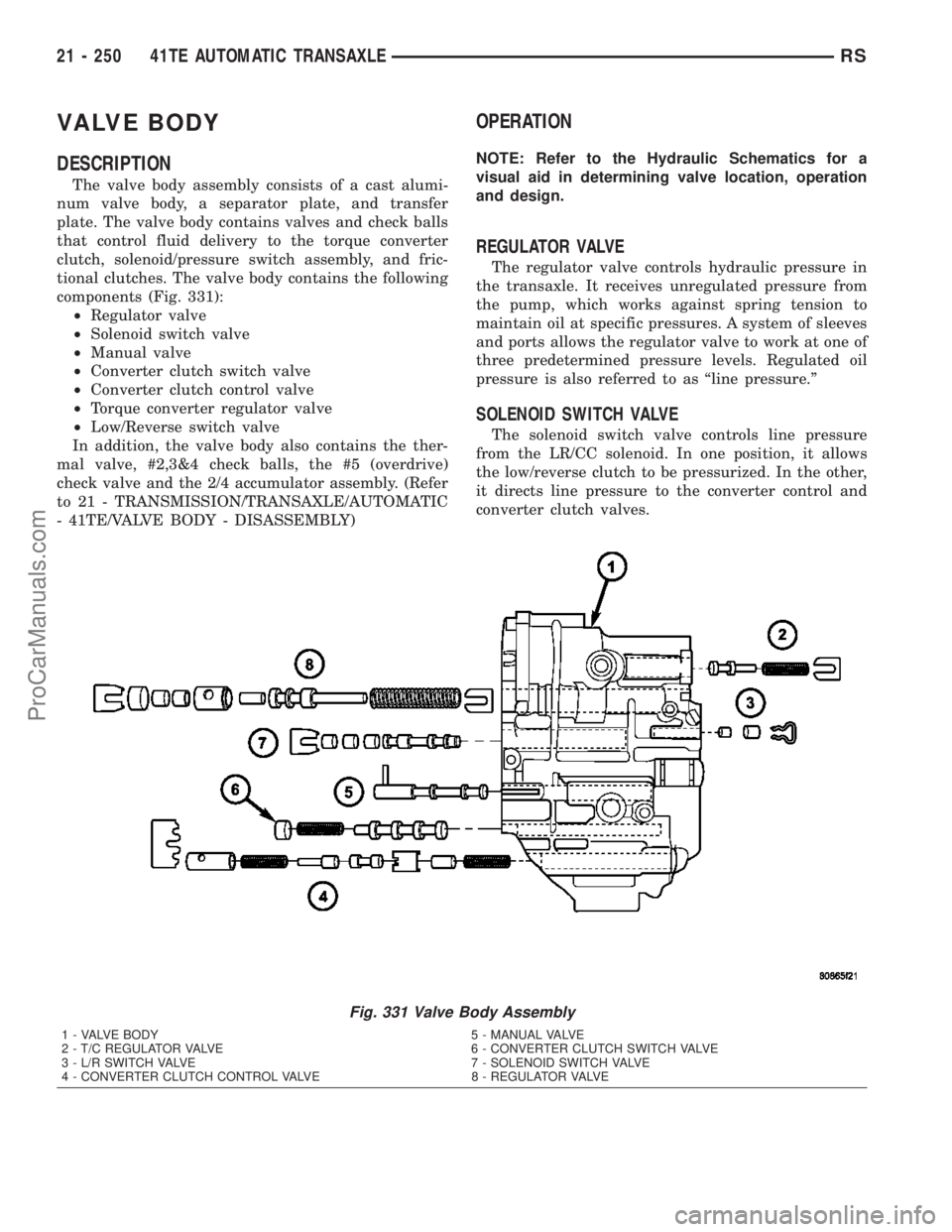
components (Fig. 331):
²Regulator valve
²Solenoid switch valve
²Manual valve
²Converter clutch switch valve
²Converter clutch control valve
²Torque converter regulator valve
²Low/Reverse switch valve
In addition, the valve body also contains the ther-
mal valve, #2,3&4 check balls, the #5 (overdrive)
check valve and the 2/4 accumulator assembly. (Refer
to 21 - TRANSMISSION/TRANSAXLE/AUTOMATIC
- 41TE/VALVE BODY - DISASSEMBLY)
OPERATION
NOTE: Refer to the Hydraulic Schematics for a
visual aid in determining valve location, operation
and design.
REGULATOR VALVE
The regulator valve controls hydraulic pressure in
the transaxle. It receives unregulated pressure from
the pump, which works against spring tension to
maintain oil at specific pressures. A system of sleeves
and ports allows the regulator valve to work at one of
three predetermined pressure levels. Regulated oil
pressure is also referred to as ªline pressure.º
SOLENOID SWITCH VALVE
The solenoid switch valve controls line pressure
from the LR/CC solenoid. In one position, it allows
the low/reverse clutch to be pressurized. In the other,
it directs line pressure to the converter control and
converter clutch valves.
Fig. 331 Valve Body Assembly
1 - VALVE BODY 5 - MANUAL VALVE
2 - T/C REGULATOR VALVE 6 - CONVERTER CLUTCH SWITCH VALVE
3 - L/R SWITCH VALVE 7 - SOLENOID SWITCH VALVE
4 - CONVERTER CLUTCH CONTROL VALVE 8 - REGULATOR VALVE
21 - 250 41TE AUTOMATIC TRANSAXLERS
ProCarManuals.com
Page 1698 of 2177
MANUAL VALVE
The manual valve is operated by the mechanical
shift linkage. Its primary responsibility is to send
line pressure to the appropriate hydraulic circuits
and solenoids. The valve has three operating ranges
or positions.
CONVERTER CLUTCH SWITCH VALVE
The main responsibility of the converter clutch
switch valve is to control hydraulic pressure applied
to the front (off) side of the converter clutch piston.
Line pressure from the regulator valve is fed to the
torque converter regulator valve, where it passes
through the valve, and is slightly regulated. The
pressure is then directed to the converter clutch
switch valve and to the front side of the converter
clutch piston. This pressure pushes the piston back
and disengages the converter clutch.
CONVERTER CLUTCH CONTROL VALVE
The converter clutch control valve controls the
back (on) side of the torque converter clutch. When
the PCM/TCM energizes or modulates the LR/CC
solenoid to apply the converter clutch piston, both
the converter clutch control valve and the converter
control valve move, allowing pressure to be applied to
the back side of the clutch.
T/C REGULATOR VALVE
The torque converter regulator valve slightly regu-
lates the flow of fluid to the torque converter.
LOW/REVERSE SWITCH VALVE
The low/reverse clutch is applied from different
sources, depending on whether low (1st) gear or
reverse is selected. The low/reverse switch valve
alternates positions depending on from which direc-
tion fluid pressure is applied. By design, when the
valve is shifted by fluid pressure from one channel,
the opposing channel is blocked. The switch valve
alienates the possibility of a sticking ball check, thus
providing consistent application of the low/reverse
clutch under all operating conditions.
REMOVAL
NOTE: If valve body is replaced or reconditioned,
the TCM Quick Learn Procedure must be per-
formed. (Refer to 8 - ELECTRICAL/ELECTRONIC
CONTROL MODULES/TRANSMISSION CONTROL
MODULE - STANDARD PROCEDURE)(1) Disconnect battery negative cable.
(2) Disconnect gearshift cable from manual valve
lever.
(3) Remove manual valve lever from manual shaft.
(4) Raise vehicle on hoist.
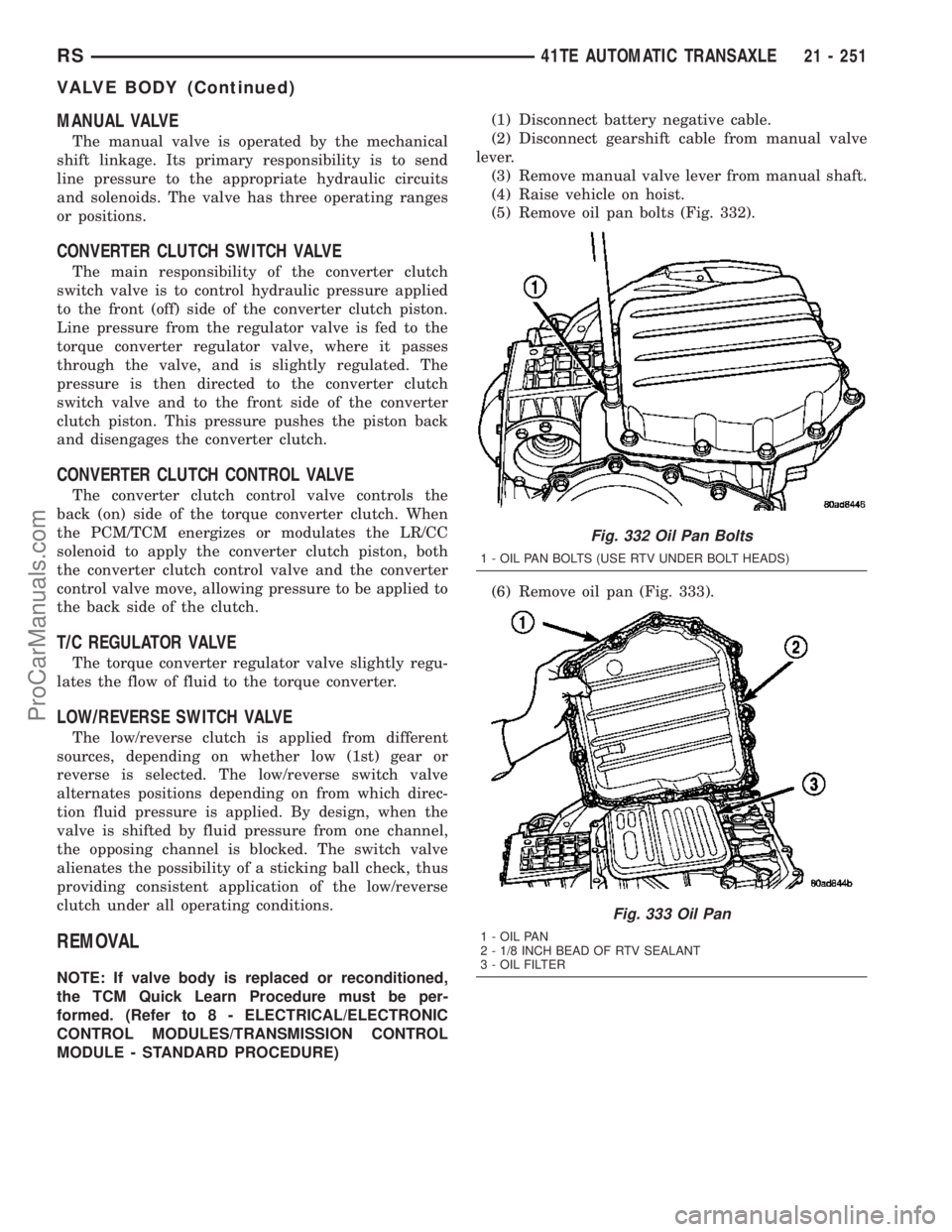
(5) Remove oil pan bolts (Fig. 332).
(6) Remove oil pan (Fig. 333).
Fig. 332 Oil Pan Bolts
1 - OIL PAN BOLTS (USE RTV UNDER BOLT HEADS)
Fig. 333 Oil Pan
1 - OIL PAN
2 - 1/8 INCH BEAD OF RTV SEALANT
3 - OIL FILTER
RS41TE AUTOMATIC TRANSAXLE21 - 251
VALVE BODY (Continued)
ProCarManuals.com
Page 1699 of 2177
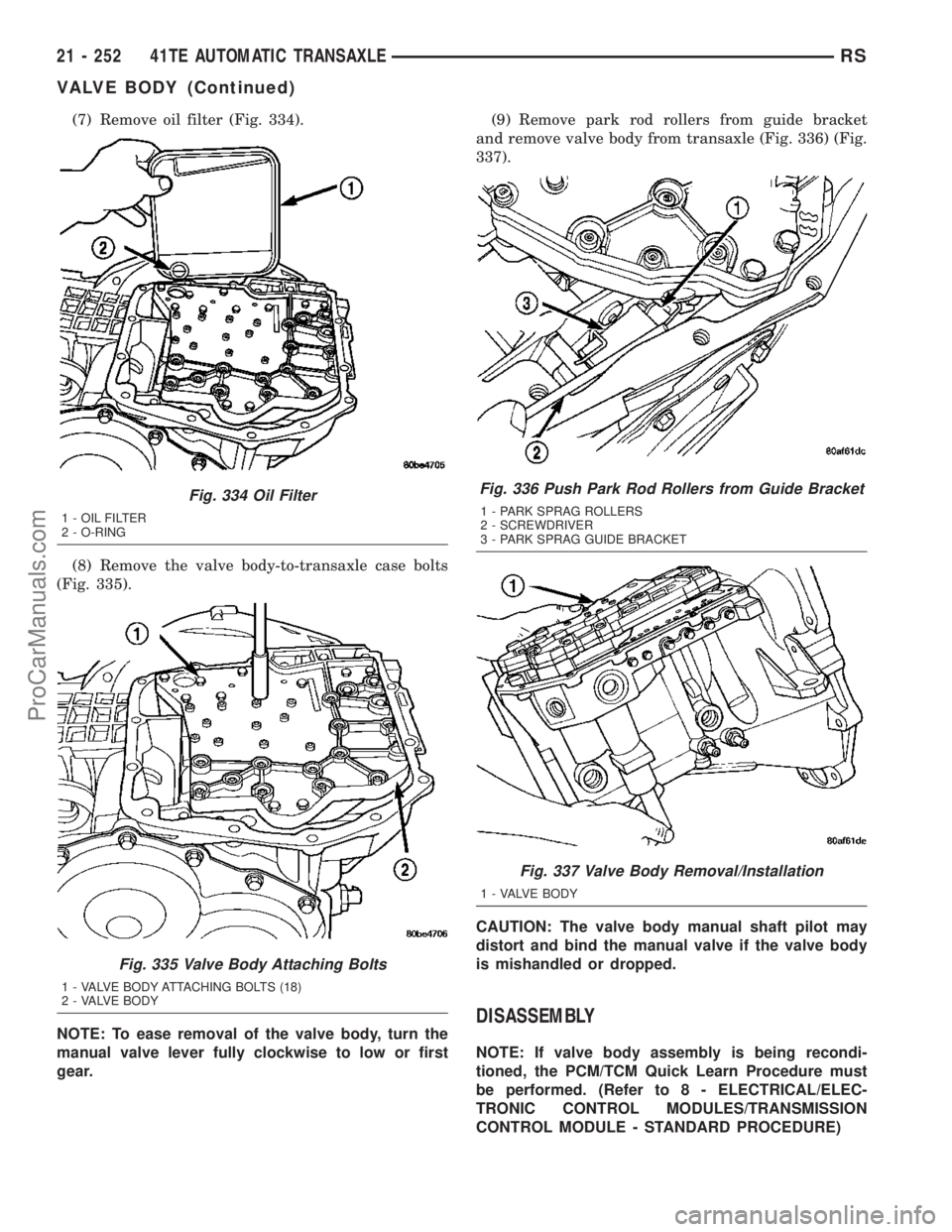
(7) Remove oil filter (Fig. 334).
(8) Remove the valve body-to-transaxle case bolts
(Fig. 335).
NOTE: To ease removal of the valve body, turn the
manual valve lever fully clockwise to low or first
gear.(9) Remove park rod rollers from guide bracket
and remove valve body from transaxle (Fig. 336) (Fig.
337).
CAUTION: The valve body manual shaft pilot may
distort and bind the manual valve if the valve body
is mishandled or dropped.
DISASSEMBLY
NOTE: If valve body assembly is being recondi-
tioned, the PCM/TCM Quick Learn Procedure must
be performed. (Refer to 8 - ELECTRICAL/ELEC-
TRONIC CONTROL MODULES/TRANSMISSION
CONTROL MODULE - STANDARD PROCEDURE)
Fig. 334 Oil Filter
1 - OIL FILTER
2 - O-RING
Fig. 335 Valve Body Attaching Bolts
1 - VALVE BODY ATTACHING BOLTS (18)
2 - VALVE BODY
Fig. 336 Push Park Rod Rollers from Guide Bracket
1 - PARK SPRAG ROLLERS
2 - SCREWDRIVER
3 - PARK SPRAG GUIDE BRACKET
Fig. 337 Valve Body Removal/Installation
1 - VALVE BODY
21 - 252 41TE AUTOMATIC TRANSAXLERS
VALVE BODY (Continued)
ProCarManuals.com
Page 1709 of 2177
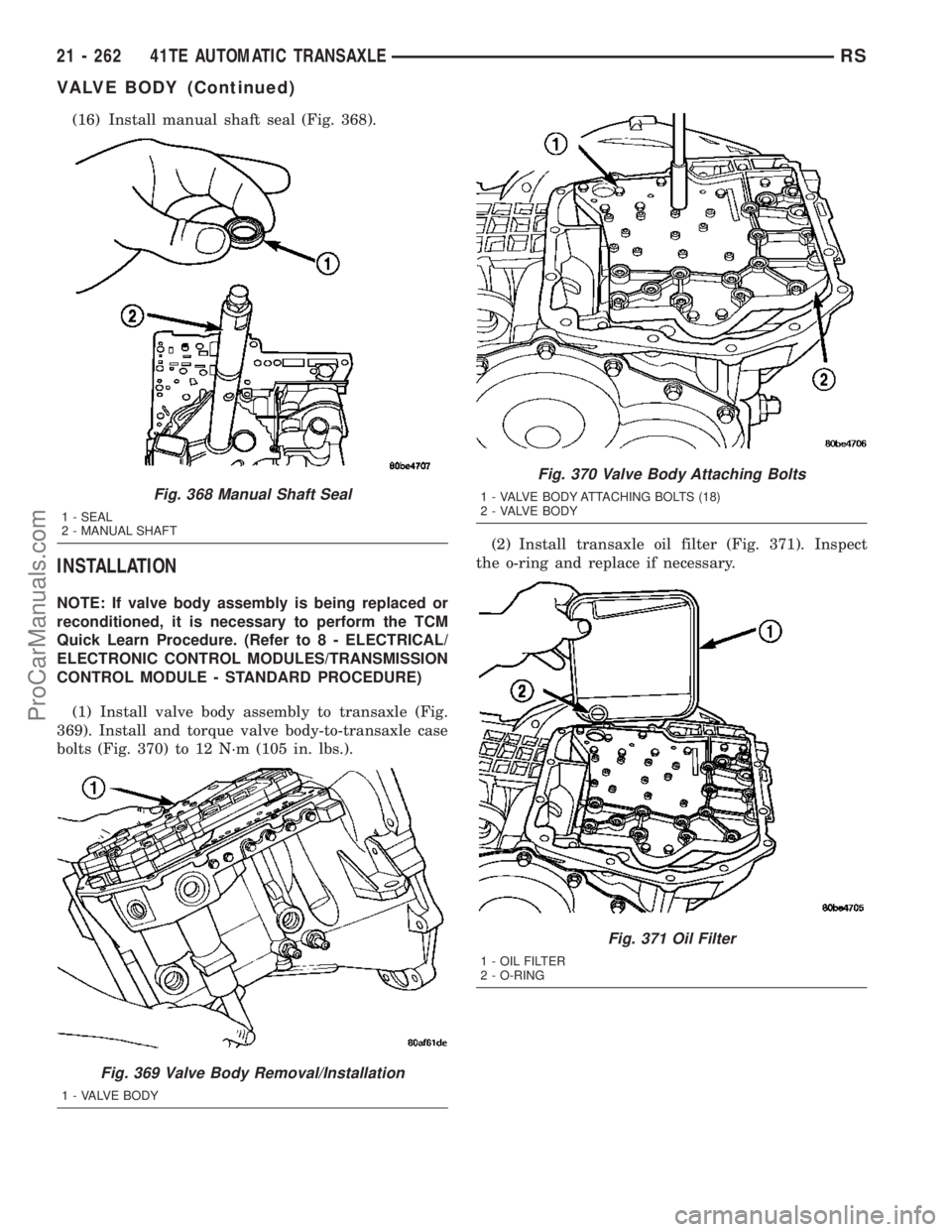
(16) Install manual shaft seal (Fig. 368).
INSTALLATION
NOTE: If valve body assembly is being replaced or
reconditioned, it is necessary to perform the TCM
Quick Learn Procedure. (Refer to 8 - ELECTRICAL/
ELECTRONIC CONTROL MODULES/TRANSMISSION
CONTROL MODULE - STANDARD PROCEDURE)
(1) Install valve body assembly to transaxle (Fig.
369). Install and torque valve body-to-transaxle case
bolts (Fig. 370) to 12 N´m (105 in. lbs.).(2) Install transaxle oil filter (Fig. 371). Inspect
the o-ring and replace if necessary.
Fig. 368 Manual Shaft Seal
1 - SEAL
2 - MANUAL SHAFT
Fig. 369 Valve Body Removal/Installation
1 - VALVE BODY
Fig. 370 Valve Body Attaching Bolts
1 - VALVE BODY ATTACHING BOLTS (18)
2 - VALVE BODY
Fig. 371 Oil Filter
1 - OIL FILTER
2 - O-RING
21 - 262 41TE AUTOMATIC TRANSAXLERS
VALVE BODY (Continued)
ProCarManuals.com
Page 1710 of 2177
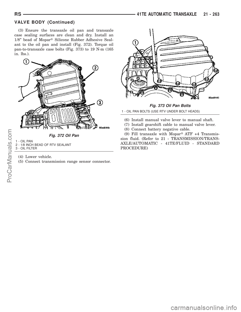
(3) Ensure the transaxle oil pan and transaxle
case sealing surfaces are clean and dry. Install an
1/8º bead of MopartSilicone Rubber Adhesive Seal-
ant to the oil pan and install (Fig. 372). Torque oil
pan-to-transaxle case bolts (Fig. 373) to 19 N´m (165
in. lbs.).
(4) Lower vehicle.
(5) Connect transmission range sensor connector.(6) Install manual valve lever to manual shaft.
(7) Install gearshift cable to manual valve lever.
(8) Connect battery negative cable.
(9) Fill transaxle with MopartATF +4 Transmis-
sion fluid. (Refer to 21 - TRANSMISSION/TRANS-
AXLE/AUTOMATIC - 41TE/FLUID - STANDARD
PROCEDURE)
Fig. 372 Oil Pan
1 - OIL PAN
2 - 1/8 INCH BEAD OF RTV SEALANT
3 - OIL FILTER
Fig. 373 Oil Pan Bolts
1 - OIL PAN BOLTS (USE RTV UNDER BOLT HEADS)
RS41TE AUTOMATIC TRANSAXLE21 - 263
VALVE BODY (Continued)
ProCarManuals.com
Page 2064 of 2177
crossmember and move the latch out of the way over
the top of the crossmember. Mark the location of
latch for reinstallation.
(6) Disconnect the hoses from the transmission oil
cooler fittings on the left side of the cooling module.
(Refer to 7 - COOLING/TRANSMISSION/TRANS
COOLER LINES - REMOVAL).
(7) Remove the nut that secures the discharge line
fitting to the condenser on the right side of the cool-
ing module.
(8) Disconnect the discharge line fitting from the
condenser inlet port.
(9) Remove the seals from the discharge line fit-
ting and discard.
(10) Install plugs in, or tape over the opened dis-
charge line fitting and the condenser inlet port.
(11) Remove the nut that secures the liquid line
fitting to the condenser on the right side of the cool-
ing module.
(12) Disconnect the liquid line fitting from the con-
denser outlet port.
(13) Remove the seals from the liquid line fitting
and discard.
(14) Install plugs in, or tape over the opened liquid
line fitting and the condenser outlet port.
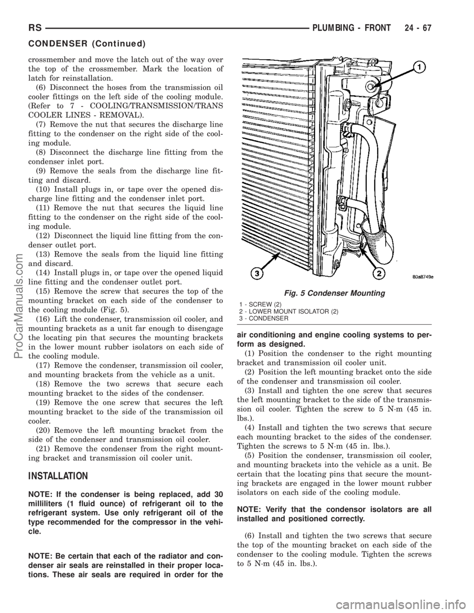
(15) Remove the screw that secures the top of the
mounting bracket on each side of the condenser to
the cooling module (Fig. 5).
(16) Lift the condenser, transmission oil cooler, and
mounting brackets as a unit far enough to disengage
the locating pin that secures the mounting brackets
in the lower mount rubber isolators on each side of
the cooling module.
(17) Remove the condenser, transmission oil cooler,
and mounting brackets from the vehicle as a unit.
(18) Remove the two screws that secure each
mounting bracket to the sides of the condenser.
(19) Remove the one screw that secures the left
mounting bracket to the side of the transmission oil
cooler.
(20) Remove the left mounting bracket from the
side of the condenser and transmission oil cooler.
(21) Remove the condenser from the right mount-
ing bracket and transmission oil cooler unit.
INSTALLATION
NOTE: If the condenser is being replaced, add 30
milliliters (1 fluid ounce) of refrigerant oil to the
refrigerant system. Use only refrigerant oil of the
type recommended for the compressor in the vehi-
cle.
NOTE: Be certain that each of the radiator and con-
denser air seals are reinstalled in their proper loca-
tions. These air seals are required in order for theair conditioning and engine cooling systems to per-
form as designed.
(1) Position the condenser to the right mounting
bracket and transmission oil cooler unit.
(2) Position the left mounting bracket onto the side
of the condenser and transmission oil cooler.
(3) Install and tighten the one screw that secures
the left mounting bracket to the side of the transmis-
sion oil cooler. Tighten the screw to 5 N´m (45 in.
lbs.).
(4) Install and tighten the two screws that secure
each mounting bracket to the sides of the condenser.
Tighten the screws to 5 N´m (45 in. lbs.).
(5) Position the condenser, transmission oil cooler,
and mounting brackets into the vehicle as a unit. Be
certain that the locating pins that secure the mount-
ing brackets are engaged in the lower mount rubber
isolators on each side of the cooling module.
NOTE: Verify that the condensor isolators are all
installed and positioned correctly.
(6) Install and tighten the two screws that secure
the top of the mounting bracket on each side of the
condenser to the cooling module. Tighten the screws
to 5 N´m (45 in. lbs.).
Fig. 5 Condenser Mounting
1 - SCREW (2)
2 - LOWER MOUNT ISOLATOR (2)
3 - CONDENSER
RSPLUMBING - FRONT24-67
CONDENSER (Continued)
ProCarManuals.com
Page 2065 of 2177
(7) Remove the tape or plugs from the condenser
outlet port and the liquid line fitting.
(8) Lubricate a new rubber O-ring seal with clean
refrigerant oil and install it on the liquid line fitting.
(9) Install a new dual plan seal and reconnect the
liquid line fitting to the condenser outlet port on the
right side of the cooling module.
(10) Install and tighten the nut that secures the
liquid line fitting to the condenser. Tighten the nut to
23 N´m (17 ft. lbs.).
(11) Remove the tape or plugs from the condenser
inlet port and the discharge line fitting.
(12) Lubricate a new rubber O-ring seal with clean
refrigerant oil and install it on the discharge line fit-
ting.
(13) Install a new dual plan seal and reconnect the
discharge line fitting to the condenser inlet port on
the right side of the cooling module.
(14) Install and tighten the nut that secures the
discharge line fitting to the condenser. Tighten the
nut to 23 N´m (17 ft. lbs.).
(15) Reconnect the hoses to the transmission oil
cooler fittings on the left side of the cooling module.
(Refer to 7 - COOLING/TRANSMISSION/TRANS
COOLER LINES - INSTALLATION).
(16) Reposition the hood latch unit to the front of
the radiator closure panel crossmember.
(17) Install and tighten the two screws that secure
the hood latch unit to the front of the radiator clo-
sure panel crossmember. Check and adjust the hood
latch as needed. Tighten the screws to 14 N´m (123
in. lbs.).
(18) Position the radiator sight shield onto the
radiator closure panel crossmember.
(19) Install and tighten the five small screws that
secure the front fascia grille inserts to the radiator
sight shield. Tighten the screws to 2 N´m (18 in. lbs.).
(20) Install and tighten the two large screws that
secure the front fascia and the outboard ends of the
radiator sight shield to the radiator closure panel
crossmember. Tighten the screws to 6 N´m (53 in.
lbs.).
(21) Evacuate the refrigerant system. (Refer to 24
- HEATING & AIR CONDITIONING/PLUMBING -
FRONT/REFRIGERANT - STANDARD PROCE-
DURE - REFRIGERANT SYSTEM EVACUATE).
(22) Charge the refrigerant system. (Refer to 24 -
HEATING & AIR CONDITIONING/PLUMBING -
FRONT/REFRIGERANT - STANDARD PROCE-
DURE - REFRIGERANT SYSTEM CHARGE).DISCHARGE LINE
REMOVAL
WARNING: REFER TO THE APPLICABLE WARN-
INGS AND CAUTIONS FOR THIS SYSTEM BEFORE
PERFORMING THE FOLLOWING OPERATION.
(Refer to 24 - HEATING & AIR CONDITIONING/
PLUMBING - FRONT - WARNING - A/C PLUMBING)
and (Refer to 24 - HEATING & AIR CONDITIONING/
PLUMBING - FRONT - CAUTION - A/C PLUMBING).
(1) Recover the refrigerant from the refrigerant
system. (Refer to 24 - HEATING & AIR CONDI-
TIONING/PLUMBING - FRONT/REFRIGERANT -
STANDARD PROCEDURE - REFRIGERANT
RECOVERY).
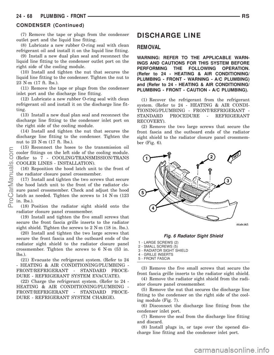
(2) Remove the two large screws that secure the
front fascia and the outboard ends of the radiator
sight shield to the radiator closure panel crossmem-
ber (Fig. 6).
(3) Remove the five small screws that secure the
front fascia grille inserts to the radiator sight shield.
(4) Remove the radiator sight shield from the radi-
ator closure panel crossmember.
(5) Remove the nut that secures the discharge line
fitting to the condenser on the right side of the cool-
ing module (Fig. 7).
(6) Disconnect the discharge line fitting from the
condenser inlet port.
(7) Remove the seal from the discharge line fitting
and discard.
(8) Install plugs in, or tape over the opened dis-
charge line fitting and the condenser inlet port.
Fig. 6 Radiator Sight Shield
1 - LARGE SCREWS (2)
2 - SMALL SCREWS (5)
3 - RADIATOR SIGHT SHIELD
4 - GRILLE INSERTS
5 - FRONT FASCIA
24 - 68 PLUMBING - FRONTRS
CONDENSER (Continued)
ProCarManuals.com