2003 CHRYSLER VOYAGER Crankshaft timing
[x] Cancel search: Crankshaft timingPage 1332 of 2177
VALVE TIMING
STANDARD PROCEDURE
STANDARD PROCEDURE - VALVE TIMING
VERIFICATION
(1) Remove front cylinder head cover and all 6
spark plugs.
(2) Rotate engine until the #2 piston is at TDC of
the compression stroke.
(3) Install a degree wheel on the crankshaft pulley.
(4) With proper adaptor, install a dial indicator
into #2 spark plug hole. Using the indicator find TDC
on the compression stroke.
(5) Position the degree wheel to zero.
(6) Remove dial indicator from spark plug hole.
(7) Place a 5.08 mm (0.200 in.) spacer between the
valve stem tip of #2 intake valve and rocker arm pad.
Allow tappet to bleed down to give a solid tappet
effect.
(8) Install a dial indicator so plunger contacts the
#2 intake valve spring retainer as nearly perpendic-
ular as possible. Zero the indicator.
(9) Rotate the engine clockwise until the intake
valve has lifted .254 mm (0.010 in.).
CAUTION: Do not turn crankshaft any further clock-
wise as intake valve might bottom and result in
serious damage.
(10) Degree wheel should read 6 degrees BTDC to
6 degrees ATDC.
STANDARD PROCEDURE - MEASURING
TIMING CHAIN WEAR
NOTE: This procedure must be performed with the
timing chain cover removed (Refer to 9 - ENGINE/
VALVE TIMING/TIMING CHAIN COVER - REMOVAL).
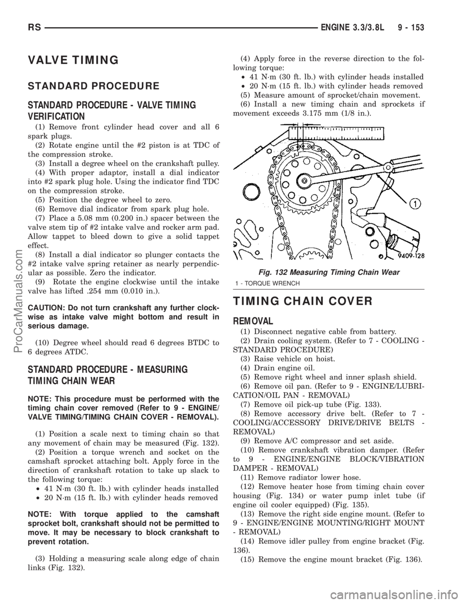
(1) Position a scale next to timing chain so that
any movement of chain may be measured (Fig. 132).
(2) Position a torque wrench and socket on the
camshaft sprocket attaching bolt. Apply force in the
direction of crankshaft rotation to take up slack to
the following torque:
²41 N´m (30 ft. lb.) with cylinder heads installed
²20 N´m (15 ft. lb.) with cylinder heads removed
NOTE: With torque applied to the camshaft
sprocket bolt, crankshaft should not be permitted to
move. It may be necessary to block crankshaft to
prevent rotation.
(3) Holding a measuring scale along edge of chain
links (Fig. 132).(4) Apply force in the reverse direction to the fol-
lowing torque:
²41 N´m (30 ft. lb.) with cylinder heads installed
²20 N´m (15 ft. lb.) with cylinder heads removed
(5) Measure amount of sprocket/chain movement.
(6) Install a new timing chain and sprockets if
movement exceeds 3.175 mm (1/8 in.).
TIMING CHAIN COVER
REMOVAL
(1) Disconnect negative cable from battery.
(2) Drain cooling system. (Refer to 7 - COOLING -
STANDARD PROCEDURE)
(3) Raise vehicle on hoist.
(4) Drain engine oil.
(5) Remove right wheel and inner splash shield.
(6) Remove oil pan. (Refer to 9 - ENGINE/LUBRI-
CATION/OIL PAN - REMOVAL)
(7) Remove oil pick-up tube (Fig. 133).
(8) Remove accessory drive belt. (Refer to 7 -
COOLING/ACCESSORY DRIVE/DRIVE BELTS -
REMOVAL)
(9) Remove A/C compressor and set aside.
(10) Remove crankshaft vibration damper. (Refer
to 9 - ENGINE/ENGINE BLOCK/VIBRATION
DAMPER - REMOVAL)
(11) Remove radiator lower hose.
(12) Remove heater hose from timing chain cover
housing (Fig. 134) or water pump inlet tube (if
engine oil cooler equipped) (Fig. 135).
(13) Remove the right side engine mount. (Refer to
9 - ENGINE/ENGINE MOUNTING/RIGHT MOUNT
- REMOVAL)
(14) Remove idler pulley from engine bracket (Fig.
136).
(15) Remove the engine mount bracket (Fig. 136).
Fig. 132 Measuring Timing Chain Wear
1 - TORQUE WRENCH
RSENGINE 3.3/3.8L9 - 153
ProCarManuals.com
Page 1334 of 2177
(17) Remove the water pump for cover removal
clearance. (Refer to 7 - COOLING/ENGINE/WATER
PUMP - REMOVAL)
(18) Remove the bolt attaching the power steering
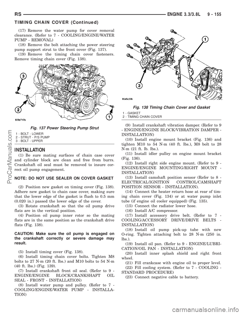
pump support strut to the front cover (Fig. 137).
(19) Remove the timing chain cover fasteners.
Remove timing chain cover (Fig. 138).
INSTALLATION
(1) Be sure mating surfaces of chain case cover
and cylinder block are clean and free from burrs.
Crankshaft oil seal must be removed to insure cor-
rect oil pump engagement.
NOTE: DO NOT USE SEALER ON COVER GASKET
(2) Position new gasket on timing cover (Fig. 138).
Adhere new gasket to chain case cover, making sure
that the lower edge of the gasket is flush to 0.5 mm
(0.020 in.) passed the lower edge of the cover.
(3) Rotate crankshaft so that the oil pump drive
flats are in the vertical position.
(4) Position oil pump inner rotor so the mating
flats are in the same position as the crankshaft drive
flats (Fig. 138).
CAUTION: Make sure the oil pump is engaged on
the crankshaft correctly or severe damage may
result.
(5) Install timing cover (Fig. 138).
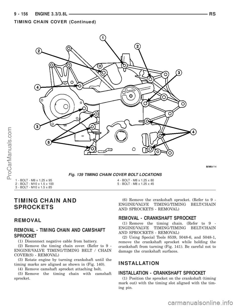
(6) Install timing chain cover bolts. Tighten M8
bolts to 27 N´m (20 ft. lbs.) and M10 bolts to 54 N´m
(40 ft. lbs.) (Fig. 139).
(7) Install crankshaft front oil seal. (Refer to 9 -
ENGINE/ENGINE BLOCK/CRANKSHAFT OIL
SEAL - FRONT - INSTALLATION)
(8) Install water pump and pulley. (Refer to 7 -
COOLING/ENGINE/WATER PUMP - INSTALLA-
TION)(9) Install crankshaft vibration damper. (Refer to 9
- ENGINE/ENGINE BLOCK/VIBRATION DAMPER -
INSTALLATION)
(10) Install engine mount bracket (Fig. 136) and
tighten M10 to 54 N´m (40 ft. lbs.), M8 bolt to 28
N´m (21 ft. lb. lbs.).
(11) Install idler pulley on engine mount bracket
(Fig. 136).
(12) Install right side engine mount. (Refer to 9 -
ENGINE/ENGINE MOUNTING/RIGHT MOUNT -
INSTALLATION)
(13) Install camshaft position sensor (Refer to 8 -
ELECTRICAL/IGNITION CONTROL/CAMSHAFT
POSITION SENSOR - INSTALLATION).
(14) Connect the heater return hose at rear of tim-
ing chain cover (Fig. 134) or at water pump inlet
tube (if engine oil cooler equipped) (Fig. 135).
(15) Connect the radiator lower hose.
(16) Install A/C compressor.
(17) Install accessory drive belt. (Refer to 7 -
COOLING/ACCESSORY DRIVE/DRIVE BELTS -
INSTALLATION)
(18) Install oil pump pick-up tube with new
O-ring. Tighten attaching bolt to 28 N´m (250 in.
lbs.).
(19) Install oil pan. (Refer to 9 - ENGINE/LUBRI-
CATION/OIL PAN - INSTALLATION)
(20) Install inner splash shield and right front
wheel.
(21) Fill crankcase with engine oil to proper level.
(22) Fill cooling system. (Refer to 7 - COOLING -
STANDARD PROCEDURE)
(23) Connect negative cable to battery.
Fig. 137 Power Steering Pump Strut
1 - BOLT - LOWER
2 - STRUT - P/S PUMP
3 - BOLT - UPPER
Fig. 138 Timing Chain Cover and Gasket
1 - GASKET
2 - TIMING CHAIN COVER
RSENGINE 3.3/3.8L9 - 155
TIMING CHAIN COVER (Continued)
ProCarManuals.com
Page 1335 of 2177
TIMING CHAIN AND
SPROCKETS
REMOVAL
REMOVAL - TIMING CHAIN AND CAMSHAFT
SPROCKET
(1) Disconnect negative cable from battery.
(2) Remove the timing chain cover. (Refer to 9 -
ENGINE/VALVE TIMING/TIMING BELT / CHAIN
COVER(S) - REMOVAL)
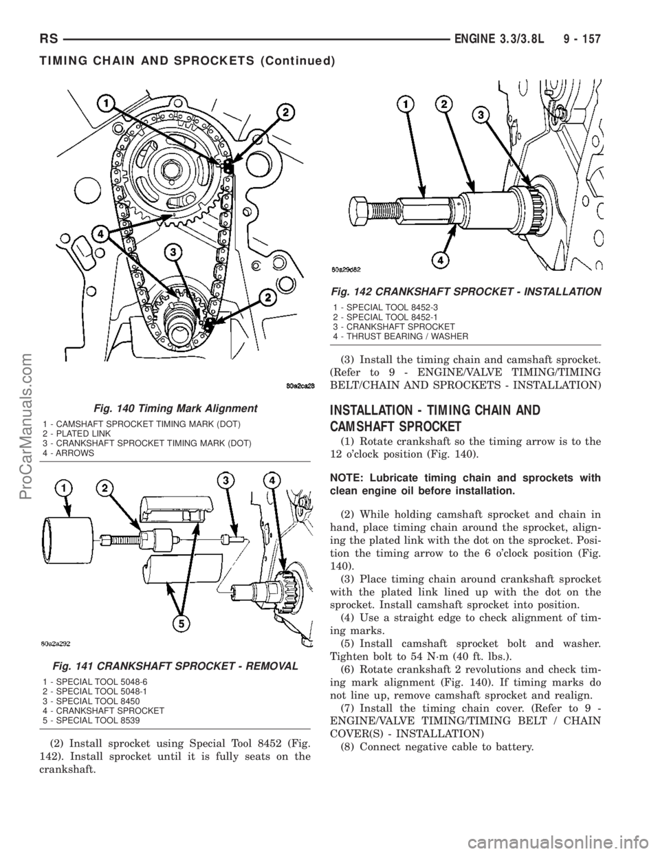
(3) Rotate engine by turning crankshaft until the
timing marks are aligned as shown in (Fig. 140).
(4) Remove camshaft sprocket attaching bolt.
(5) Remove the timing chain with camshaft
sprocket.(6) Remove the crankshaft sprocket. (Refer to 9 -
ENGINE/VALVE TIMING/TIMING BELT/CHAIN
AND SPROCKETS - REMOVAL)
REMOVAL - CRANKSHAFT SPROCKET
(1) Remove the timing chain. (Refer to 9 -
ENGINE/VALVE TIMING/TIMING BELT/CHAIN
AND SPROCKETS - REMOVAL)
(2) Using Special Tools 8539, 5048-6, and 5048-1,
remove the crankshaft sprocket while holding the
crankshaft from turning (Fig. 141). Be careful not to
damage the crankshaft surfaces.
INSTALLATION
INSTALLATION - CRANKSHAFT SPROCKET
(1) Position the sprocket on the crankshaft (timing
mark out) with the timing slot aligned with the tim-
ing pin.
Fig. 139 TIMING CHAIN COVER BOLT LOCATIONS
1 - BOLT - M8 x 1.25 x 95 4 - BOLT - M8 x 1.25 x 80
2 - BOLT - M10 x 1.5 x 100 5 - BOLT - M8 x 1.25 x 45
3 - BOLT - M10 x 1.5 x 85
9 - 156 ENGINE 3.3/3.8LRS
TIMING CHAIN COVER (Continued)
ProCarManuals.com
Page 1336 of 2177
(2) Install sprocket using Special Tool 8452 (Fig.
142). Install sprocket until it is fully seats on the
crankshaft.(3) Install the timing chain and camshaft sprocket.
(Refer to 9 - ENGINE/VALVE TIMING/TIMING
BELT/CHAIN AND SPROCKETS - INSTALLATION)
INSTALLATION - TIMING CHAIN AND
CAMSHAFT SPROCKET
(1) Rotate crankshaft so the timing arrow is to the
12 o'clock position (Fig. 140).
NOTE: Lubricate timing chain and sprockets with
clean engine oil before installation.
(2) While holding camshaft sprocket and chain in
hand, place timing chain around the sprocket, align-
ing the plated link with the dot on the sprocket. Posi-
tion the timing arrow to the 6 o'clock position (Fig.
140).
(3) Place timing chain around crankshaft sprocket
with the plated link lined up with the dot on the
sprocket. Install camshaft sprocket into position.
(4) Use a straight edge to check alignment of tim-
ing marks.
(5) Install camshaft sprocket bolt and washer.
Tighten bolt to 54 N´m (40 ft. lbs.).
(6) Rotate crankshaft 2 revolutions and check tim-
ing mark alignment (Fig. 140). If timing marks do
not line up, remove camshaft sprocket and realign.
(7) Install the timing chain cover. (Refer to 9 -
ENGINE/VALVE TIMING/TIMING BELT / CHAIN
COVER(S) - INSTALLATION)
(8) Connect negative cable to battery.
Fig. 140 Timing Mark Alignment
1 - CAMSHAFT SPROCKET TIMING MARK (DOT)
2 - PLATED LINK
3 - CRANKSHAFT SPROCKET TIMING MARK (DOT)
4 - ARROWS
Fig. 141 CRANKSHAFT SPROCKET - REMOVAL
1 - SPECIAL TOOL 5048-6
2 - SPECIAL TOOL 5048-1
3 - SPECIAL TOOL 8450
4 - CRANKSHAFT SPROCKET
5 - SPECIAL TOOL 8539
Fig. 142 CRANKSHAFT SPROCKET - INSTALLATION
1 - SPECIAL TOOL 8452-3
2 - SPECIAL TOOL 8452-1
3 - CRANKSHAFT SPROCKET
4 - THRUST BEARING / WASHER
RSENGINE 3.3/3.8L9 - 157
TIMING CHAIN AND SPROCKETS (Continued)
ProCarManuals.com
Page 1378 of 2177
1 second. Therefore, battery voltage is not supplied to
the fuel pump, ignition coil, fuel injectors and heated
oxygen sensors.
ENGINE START-UP MODE
This is an OPEN LOOP mode. If the vehicle is in
park or neutral (automatic transaxles) or the clutch
pedal is depressed (manual transaxles) the ignition
switch energizes the starter relay when the engine is
not running. The following actions occur when the
starter motor is engaged.
²If the PCM receives the camshaft position sensor
and crankshaft position sensor signals, it energizes
the Auto Shutdown (ASD) relay and fuel pump relay.
If the PCM does not receive both signals within
approximately one second, it will not energize the
ASD relay and fuel pump relay. The ASD and fuel
pump relays supply battery voltage to the fuel pump,
fuel injectors, ignition coil, (EGR solenoid and PCV
heater if equipped) and heated oxygen sensors.
²The PCM energizes the injectors (on the 69É
degree falling edge) for a calculated pulse width until
it determines crankshaft position from the camshaft
position sensor and crankshaft position sensor sig-
nals. The PCM determines crankshaft position within
1 engine revolution.
²After determining crankshaft position, the PCM
begins energizing the injectors in sequence. It adjusts
injector pulse width and controls injector synchroni-
zation by turning the individual ground paths to the
injectors On and Off.
²When the engine idles within 64 RPM of its
target RPM, the PCM compares current MAP sensor
value with the atmospheric pressure value received
during the Ignition Switch On (zero RPM) mode.
Once the ASD and fuel pump relays have been
energized, the PCM determines injector pulse width
based on the following:
²MAP
²Engine RPM
²Battery voltage
²Engine coolant temperature
²Inlet/Intake air temperature (IAT)
²Throttle position
²The number of engine revolutions since cranking
was initiated
During Start-up the PCM maintains ignition tim-
ing at 9É BTDC.
ENGINE WARM-UP MODE
This is an OPEN LOOP mode. The following inputs
are received by the PCM:
²Manifold Absolute Pressure (MAP)
²Crankshaft position (engine speed)
²Engine coolant temperature
²Inlet/Intake air temperature (IAT)²Camshaft position
²Knock sensor
²Throttle position
²A/C switch status
²Battery voltage
²Vehicle speed
²Speed control
²O2 sensors
The PCM adjusts injector pulse width and controls
injector synchronization by turning the individual
ground paths to the injectors On and Off.
The PCM adjusts ignition timing and engine idle
speed. Engine idle speed is adjusted through the idle
air control motor.
CRUISE OR IDLE MODE
When the engine is at operating temperature this
is a CLOSED LOOP mode. During cruising or idle
the following inputs are received by the PCM:
²Manifold absolute pressure
²Crankshaft position (engine speed)
²Inlet/Intake air temperature
²Engine coolant temperature
²Camshaft position
²Knock sensor
²Throttle position
²Exhaust gas oxygen content (O2 sensors)
²A/C switch status
²Battery voltage
²Vehicle speed
The PCM adjusts injector pulse width and controls
injector synchronization by turning the individual
ground paths to the injectors On and Off.
The PCM adjusts engine idle speed and ignition
timing. The PCM adjusts the air/fuel ratio according
to the oxygen content in the exhaust gas (measured
by the upstream and downstream heated oxygen sen-
sor).
The PCM monitors for engine misfire. During
active misfire and depending on the severity, the
PCM either continuously illuminates or flashes the
malfunction indicator lamp (Check Engine light on
instrument panel). Also, the PCM stores an engine
misfire DTC in memory, if 2nd trip with fault.
The PCM performs several diagnostic routines.
They include:
²Oxygen sensor monitor
²Downstream heated oxygen sensor diagnostics
during open loop operation (except for shorted)
²Fuel system monitor
²EGR monitor (if equipped)
²Purge system monitor
²Catalyst efficiency monitor
²All inputs monitored for proper voltage range,
rationality.
RSFUEL INJECTION14-19
FUEL INJECTION (Continued)
ProCarManuals.com
Page 1383 of 2177
INSTALLATION
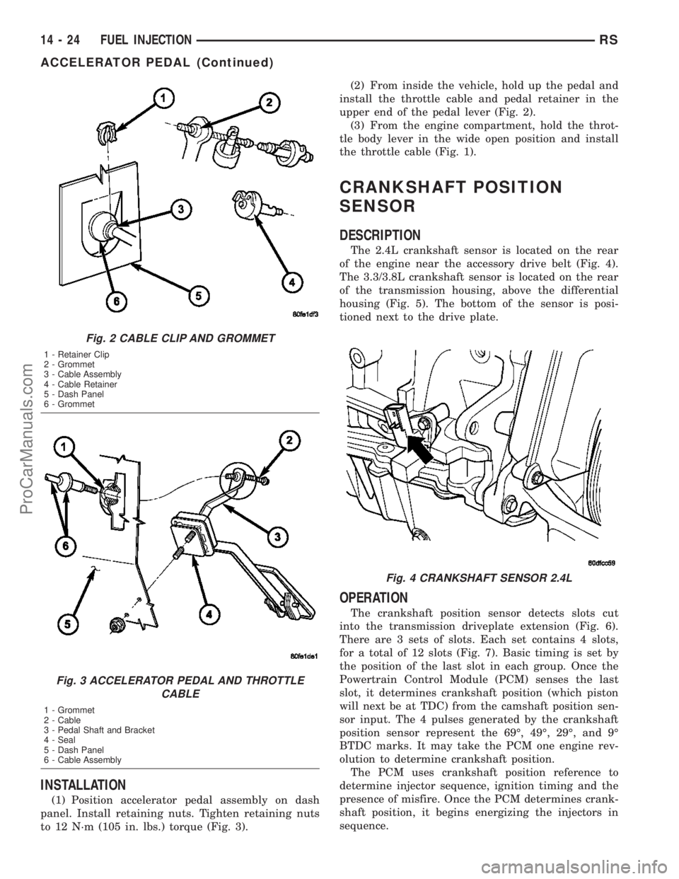
(1) Position accelerator pedal assembly on dash
panel. Install retaining nuts. Tighten retaining nuts
to 12 N´m (105 in. lbs.) torque (Fig. 3).(2) From inside the vehicle, hold up the pedal and
install the throttle cable and pedal retainer in the
upper end of the pedal lever (Fig. 2).
(3) From the engine compartment, hold the throt-
tle body lever in the wide open position and install
the throttle cable (Fig. 1).
CRANKSHAFT POSITION
SENSOR
DESCRIPTION
The 2.4L crankshaft sensor is located on the rear
of the engine near the accessory drive belt (Fig. 4).
The 3.3/3.8L crankshaft sensor is located on the rear
of the transmission housing, above the differential
housing (Fig. 5). The bottom of the sensor is posi-
tioned next to the drive plate.
OPERATION
The crankshaft position sensor detects slots cut
into the transmission driveplate extension (Fig. 6).
There are 3 sets of slots. Each set contains 4 slots,
for a total of 12 slots (Fig. 7). Basic timing is set by
the position of the last slot in each group. Once the
Powertrain Control Module (PCM) senses the last
slot, it determines crankshaft position (which piston
will next be at TDC) from the camshaft position sen-
sor input. The 4 pulses generated by the crankshaft
position sensor represent the 69É, 49É, 29É, and 9É
BTDC marks. It may take the PCM one engine rev-
olution to determine crankshaft position.
The PCM uses crankshaft position reference to
determine injector sequence, ignition timing and the
presence of misfire. Once the PCM determines crank-
shaft position, it begins energizing the injectors in
sequence.
Fig. 2 CABLE CLIP AND GROMMET
1 - Retainer Clip
2 - Grommet
3 - Cable Assembly
4 - Cable Retainer
5 - Dash Panel
6 - Grommet
Fig. 3 ACCELERATOR PEDAL AND THROTTLE
CABLE
1 - Grommet
2 - Cable
3 - Pedal Shaft and Bracket
4 - Seal
5 - Dash Panel
6 - Cable Assembly
Fig. 4 CRANKSHAFT SENSOR 2.4L
14 - 24 FUEL INJECTIONRS
ACCELERATOR PEDAL (Continued)
ProCarManuals.com
Page 1384 of 2177
REMOVAL
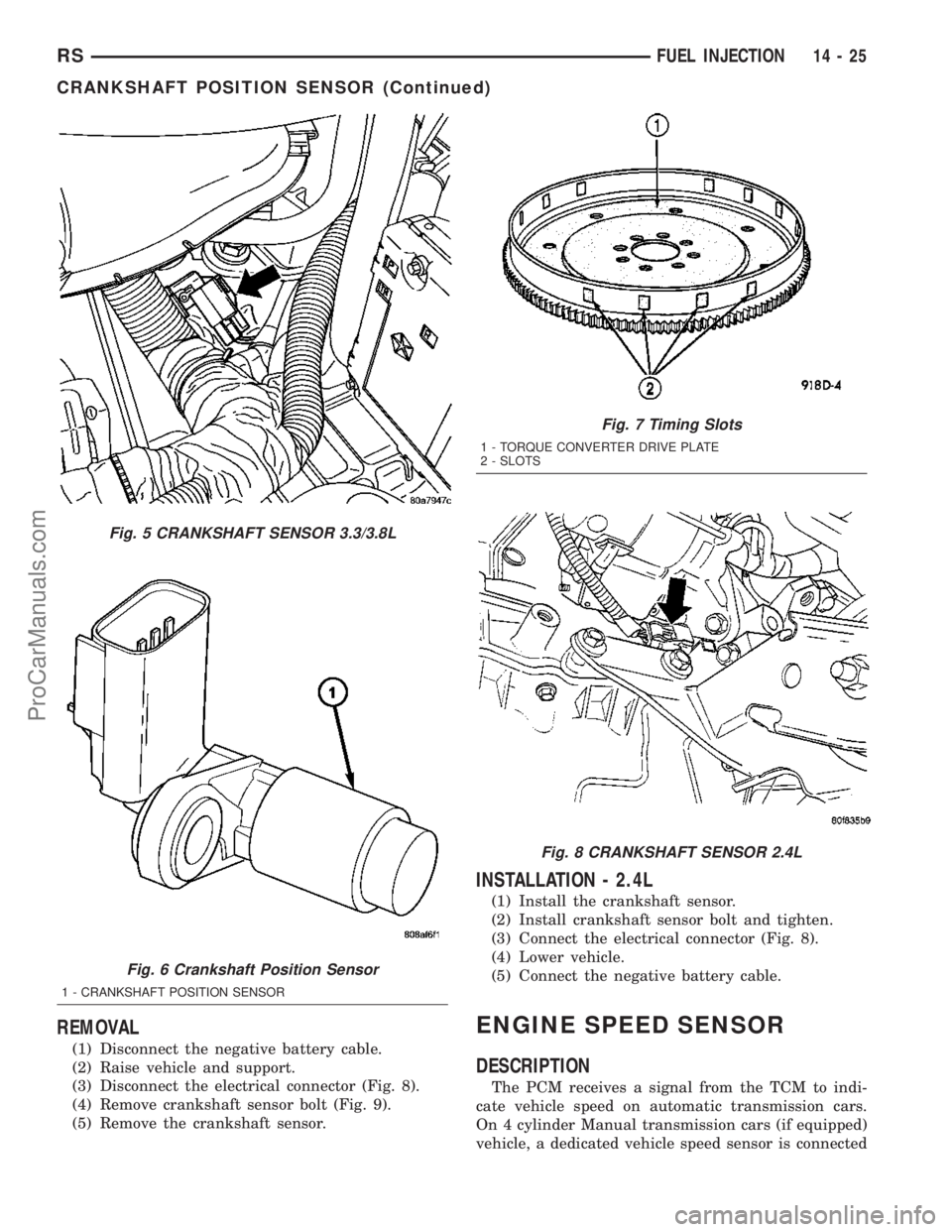
(1) Disconnect the negative battery cable.
(2) Raise vehicle and support.
(3) Disconnect the electrical connector (Fig. 8).
(4) Remove crankshaft sensor bolt (Fig. 9).
(5) Remove the crankshaft sensor.
INSTALLATION - 2.4L
(1) Install the crankshaft sensor.
(2) Install crankshaft sensor bolt and tighten.
(3) Connect the electrical connector (Fig. 8).
(4) Lower vehicle.
(5) Connect the negative battery cable.
ENGINE SPEED SENSOR
DESCRIPTION
The PCM receives a signal from the TCM to indi-
cate vehicle speed on automatic transmission cars.
On 4 cylinder Manual transmission cars (if equipped)
vehicle, a dedicated vehicle speed sensor is connected
Fig. 5 CRANKSHAFT SENSOR 3.3/3.8L
Fig. 6 Crankshaft Position Sensor
1 - CRANKSHAFT POSITION SENSOR
Fig. 7 Timing Slots
1 - TORQUE CONVERTER DRIVE PLATE
2 - SLOTS
Fig. 8 CRANKSHAFT SENSOR 2.4L
RSFUEL INJECTION14-25
CRANKSHAFT POSITION SENSOR (Continued)
ProCarManuals.com
Page 2147 of 2177
COOLANT LEVEL CHECK - STANDARD
PROCEDURE..........................7-5
COOLANT RECOVERY CONTAINER -
DESCRIPTION........................7-19
COOLANT RECOVERY CONTAINER -
INSTALLATION........................7-20
COOLANT RECOVERY CONTAINER -
OPERATION..........................7-19
COOLANT RECOVERY CONTAINER -
REMOVAL...........................7-20
COOLANT RECOVERY SYSTEM -
DIAGNOSIS AND TESTING..............7-20
COOLANT SERVICE - STANDARD
PROCEDURE.........................7-19
COOLANT TEMPERATURE SENSOR -
2.4L - DESCRIPTION, ENGINE............7-21
COOLANT TEMPERATURE SENSOR -
2.4L - INSTALLATION, ENGINE...........7-21
COOLANT TEMPERATURE SENSOR -
2.4L - REMOVAL, ENGINE...............7-21
COOLANT TEMPERATURE SENSOR -
3.3/3.8L - DESCRIPTION, ENGINE.........7-21
COOLANT TEMPERATURE SENSOR -
3.3/3.8L - INSTALLATION, ENGINE........7-22
COOLANT TEMPERATURE SENSOR -
3.3/3.8L - REMOVAL, ENGINE............7-21
COOLANT THERMOSTAT - 2.4L -
INSTALLATION, ENGINE................7-23
COOLANT THERMOSTAT - 2.4L -
REMOVAL, ENGINE....................7-23
COOLANT THERMOSTAT - 3.3/3.8L -
INSTALLATION, ENGINE................7-24
COOLANT THERMOSTAT - 3.3/3.8L -
REMOVAL, ENGINE......................7-23
COOLANT THERMOSTAT - DESCRIPTION,
ENGINE.............................7-22
COOLANT THERMOSTAT - DIAGNOSIS
AND TESTING, ENGINE.................7-23
COOLANT THERMOSTAT - OPERATION,
ENGINE.............................7-22
COOLER - DESCRIPTION, FLUID.........19-44
COOLER - DESCRIPTION,
TRANSMISSION OIL...................7-37
COOLER - INSPECTION, TRANSMISSION
OIL ................................7-37
COOLER - INSTALLATION, FLUID........19-45
COOLER - INSTALLATION,
TRANSMISSION OIL...................7-37
COOLER & LINES - DESCRIPTION, OIL . . . 9-138
COOLER & LINES - INSTALLATION, OIL . . . 9-138
COOLER & LINES - OPERATION, OIL.....9-138
COOLER & LINES - REMOVAL, OIL.......9-138
COOLER - OPERATION, FLUID..........19-44
COOLER - REMOVAL, FLUID............19-44
COOLER - REMOVAL, TRANSMISSION
OIL ................................7-37
COOLER LINES - INSTALLATION,
TRANSMISSION OIL...................7-38
COOLER LINES - REMOVAL,
TRANSMISSION OIL...................7-38
COOLING SYSTEM - DESCRIPTION........7-1
COOLING SYSTEM - DIAGNOSIS AND
TESTING, ENGINE.....................7-14
COOLING SYSTEM - OPERATION..........7-2
COOLING SYSTEM AERATION -
DIAGNOSIS AND TESTING...............7-3
COOLING SYSTEM DEAERATION -
DIAGNOSIS AND TESTING
...............7-4
COOLING SYSTEM DRAINING -
STANDARD PROCEDURE
.................7-4
COOLING SYSTEM FILLING - STANDARD
PROCEDURE
..........................7-5
COOLING SYSTEM FLOW CHECK -
DIAGNOSIS AND TESTING
...............7-3
COOLING SYSTEM LEAK TEST -
DIAGNOSIS AND TESTING
...............7-2
COOLING SYSTEM PRESSURE CAP
TESTING - DIAGNOSIS AND TESTING
......7-27
COOLING SYSTEM, SPECIAL TOOLS
.......7-6
CORE - DESCRIPTION, HEATER
....24-74,24-98
CORE - INSTALLATION, HEATER
. . . 24-100,24-78
CORE - OPERATION, HEATER
......24-74,24-98
CORE - REMOVAL, HEATER
.......24-76,24-99
CORE AND OIL GALLERY PLUGS -
STANDARD PROCEDURE, ENGINE
....9-10,9-86
CORE EXTENSION TUBES -
INSTALLATION, HEATER
...............24-77CORE EXTENSION TUBES - REMOVAL,
HEATER ............................24-75
CORE FILLING - STANDARD
PROCEDURE, HEATER.................24-98
COUPLER - DESCRIPTION, VISCOUS......3-41
COUPLER - OPERATION, VISCOUS........3-42
COURTESY LAMP - INSTALLATION.......8L-26
COURTESY LAMP - REMOVAL..........8L-26
COVER - CLEANING, CYLINDER HEAD.....9-31
COVER - DESCRIPTION, SHIFT.........21-113
COVER - DESCRIPTION, WHEEL.........22-19
COVER - INSPECTION, CYLINDER HEAD . . . 9-31
COVER - INSTALLATION, BENCH SEAT
BACK.............................23-102
COVER - INSTALLATION, CYLINDER
HEAD...............................9-31
COVER - INSTALLATION, DRIVER
AIRBAG TRIM........................8O-7
COVER - INSTALLATION, FRONT SEAT
CUSHION SIDE......................23-93
COVER - INSTALLATION, FRONT SEAT
TRACK - REAR......................23-95
COVER - INSTALLATION, FRONT
SEATBACK..........................23-92
COVER - INSTALLATION, INSTRUMENT
PANEL TOP.........................23-67
COVER - INSTALLATION, LOWER
STEERING COLUMN..................23-69
COVER - INSTALLATION, OVER
STEERING COLUMN..................23-69
COVER - INSTALLATION, TIMING CHAIN....9-155
COVER - INSTALLATION, WHEEL........22-19
COVER - LEFT - INSTALLATION,
CYLINDER HEAD.....................9-103
COVER - LEFT - REMOVAL, CYLINDER
HEAD..............................9-103
COVER - QUAD BUCKET, 50/50 SPLIT,
BENCH - INSTALLATION, SEAT
CUSHION...........................23-99
COVER - QUAD BUCKET, 50/50 SPLIT,
BENCH - REMOVAL, SEAT CUSHION......23-98
COVER - REMOVAL, BENCH SEAT BACK . . 23-102
COVER - REMOVAL, CYLINDER HEAD.....9-31
COVER - REMOVAL, DRIVER AIRBAG
TRIM...............................8O-6
COVER - REMOVAL, FRONT SEAT
CUSHION SIDE......................23-93
COVER - REMOVAL, FRONT SEAT TRACK
- REAR............................23-95
COVER - REMOVAL, FRONT SEATBACK . . . 23-92
COVER - REMOVAL, INSTRUMENT
PANEL TOP.........................23-67
COVER - REMOVAL, LOWER STEERING
COLUMN...........................23-69
COVER - REMOVAL, OVER STEERING
COLUMN...........................23-69
COVER - REMOVAL, TIMING CHAIN......9-153
COVER - REMOVAL, WHEEL............22-19
COVER - RIGHT - INSTALLATION,
CYLINDER HEAD.....................9-103
COVER - RIGHT - REMOVAL, CYLINDER
HEAD..............................9-102
COVER AND DISC RUNOUT - DIAGNOSIS
AND TESTING, CLUTCH.................6-6
COVER BACKING PLATE -
INSTALLATION, STEERING COLUMN......23-69
COVER BACKING PLATE - REMOVAL,
STEERING COLUMN..................23-69
COVER BALL BEARING - INSTALLATION,
END ...............................21-10
COVER BALL BEARING - REMOVAL, END . . . 21-9
COVER O-RING - INSTALLATION, REAR . . . 21-20
COVER O-RING - REMOVAL, REAR.......21-19
COVER SEAL - INSTALLATION, END......21-11
COVER SEAL - INSTALLATION, INPUT
SHAFT.............................21-14
COVER SEAL - REMOVAL, END..........21-11
COVER SEAL - REMOVAL, INPUT SHAFT . . 21-13
COVER(S) - DESCRIPTION, CYLINDER
HEAD
..............................9-102
COVER(S) - INSTALLATION, TIMING
BELT
...............................9-62
COVERS - QUAD BUCKET, 50/50 SPLIT,
BENCH - INSTALLATION, SEAT BACK
HINGE
............................23-100
COVERS - QUAD BUCKET, 50/50 SPLIT,
BENCH - REMOVAL, SEAT BACK HINGE
. . 23-100
COVER(S) - REMOVAL, TIMING BELT
......9-61COWL GRILLE - INSTALLATION.........23-50
COWL GRILLE - REMOVAL.............23-49
COWL TRIM - INSTALLATION...........23-75
COWL TRIM - REMOVAL...............23-75
C-PILLAR - INSTALLATION, SEAT BELT
HEIGHT ADJUSTER-BOR.............8O-12
C-PILLAR - REMOVAL, SEAT BELT
HEIGHT ADJUSTER-BOR.............8O-12
C-PILLAR TRIM - INSTALLATION........23-76
C-PILLAR TRIM - REMOVAL............23-75
CRADLE CROSSMEMBER -
DESCRIPTION, FRONT..................13-9
CRADLE CROSSMEMBER THREAD
REPAIR - DESCRIPTION, FRONT..........13-9
CRANK - INSTALLATION, WINDOW.......23-21
CRANK - REMOVAL, WINDOW..........23-21
CRANKSHAFT - INSPECTION.............9-37
CRANKSHAFT - INSTALLATION...........9-38
CRANKSHAFT - REMOVAL..............9-37
CRANKSHAFT END PLAY - STANDARD
PROCEDURE.........................9-36
CRANKSHAFT END PLAY - STANDARD
PROCEDURE, MEASURING.............9-125
CRANKSHAFT MAIN BEARINGS -
INSTALLATION.......................9-124
CRANKSHAFT MAIN BEARINGS -
REMOVAL..........................9-124
CRANKSHAFT OIL SEAL - FRONT -
INSTALLATION...................9-127,9-40
CRANKSHAFT OIL SEAL - FRONT -
REMOVAL......................9-127,9-40
CRANKSHAFT OIL SEAL - REAR -
INSTALLATION...................9-129,9-42
CRANKSHAFT OIL SEAL - REAR -
REMOVAL......................9-128,9-41
CRANKSHAFT POSITION SENSOR -
DESCRIPTION.......................14-24
CRANKSHAFT POSITION SENSOR -
OPERATION.........................14-24
CRANKSHAFT POSITION SENSOR -
REMOVAL..........................14-25
CRANKSHAFT REAR OIL SEAL RETAINER
- INSTALLATION.....................9-129
CRANKSHAFT REAR OIL SEAL RETAINER
- REMOVAL.........................9-129
CRANKSHAFT SPROCKET -
INSTALLATION...................9-156,9-65
CRANKSHAFT SPROCKET - REMOVAL....9-156,
9-64
CROSSBAR - INSTALLATION, LUGGAGE
RACK..............................23-56
CROSSBAR - REMOVAL, LUGGAGE RACK . 23-55
CROSSMEMBER - DESCRIPTION, FRONT
CRADLE.............................13-9
CROSSMEMBER MOUNT BUSHINGS -
INSTALLATION, FRONT................13-12
CROSSMEMBER MOUNT BUSHINGS -
REMOVAL, FRONT....................13-12
CROSSMEMBER THREAD REPAIR -
DESCRIPTION, FRONT CRADLE..........13-9
CROSSOVER - INSTALLATION,
GEARSHIFT CABLE...................21-76
CROSSOVER - REMOVAL, GEARSHIFT
CABLE.............................21-73
CROSS-OVER PIPE - 3.3/3.8L -
INSTALLATION
........................11-6
CROSS-OVER PIPE - 3.3/3.8L -
REMOVAL
...........................11-6
CUP HOLDER - INSTALLATION
..........23-63
CUP HOLDER - INSTALLATION, QUAD
BUCKET SEAT SIDE SHIELD - NO
........23-96
CUP HOLDER - REMOVAL
..............23-63
CUP HOLDER - REMOVAL, QUAD
BUCKET SEAT SIDE SHIELD - NO
........23-96
CURB HEIGHT MEASUREMENT -
STANDARD PROCEDURE
................2-54
CUSHION - INSTALLATION, FRONT/QUAD
SEAT
..............................23-92
CUSHION - INSTALLATION, STABILIZER
BAR
.................................2-4
CUSHION - REMOVAL, FRONT/QUAD
SEAT
..............................23-92
CUSHION - REMOVAL, STABILIZER BAR
....2-4
CUSHION COVER - QUAD BUCKET, 50/50
SPLIT, BENCH - INSTALLATION, SEAT
....23-99
CUSHION COVER - QUAD BUCKET, 50/50
SPLIT, BENCH - REMOVAL, SEAT
........23-98
8 INDEXRS
Description Group-Page Description Group-Page Description Group-Page
ProCarManuals.com