2003 CHRYSLER VOYAGER Engine timing
[x] Cancel search: Engine timingPage 1207 of 2177
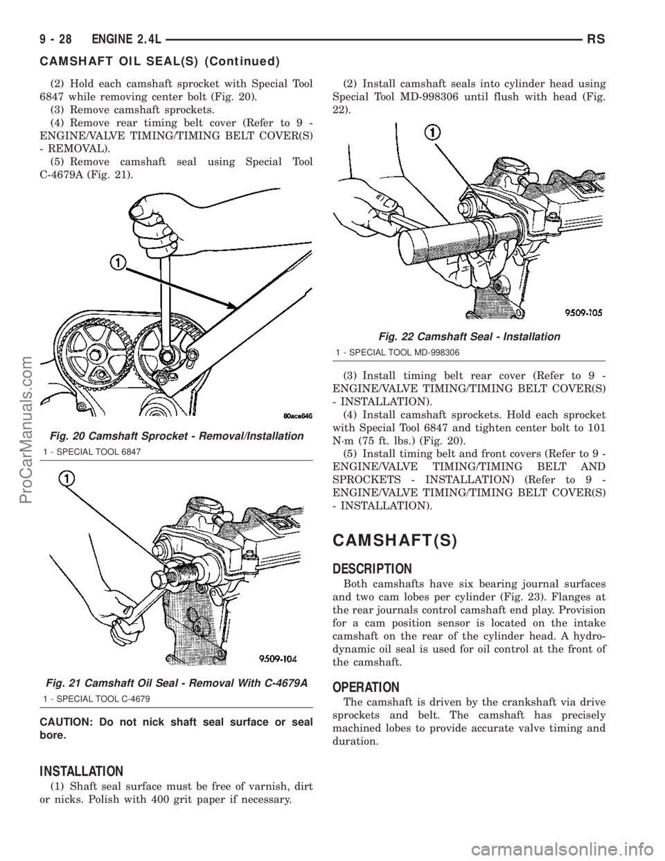
(2) Hold each camshaft sprocket with Special Tool
6847 while removing center bolt (Fig. 20).
(3) Remove camshaft sprockets.
(4) Remove rear timing belt cover (Refer to 9 -
ENGINE/VALVE TIMING/TIMING BELT COVER(S)
- REMOVAL).
(5) Remove camshaft seal using Special Tool
C-4679A (Fig. 21).
CAUTION: Do not nick shaft seal surface or seal
bore.
INSTALLATION
(1) Shaft seal surface must be free of varnish, dirt
or nicks. Polish with 400 grit paper if necessary.(2) Install camshaft seals into cylinder head using
Special Tool MD-998306 until flush with head (Fig.
22).
(3) Install timing belt rear cover (Refer to 9 -
ENGINE/VALVE TIMING/TIMING BELT COVER(S)
- INSTALLATION).
(4) Install camshaft sprockets. Hold each sprocket
with Special Tool 6847 and tighten center bolt to 101
N´m (75 ft. lbs.) (Fig. 20).
(5) Install timing belt and front covers (Refer to 9 -
ENGINE/VALVE TIMING/TIMING BELT AND
SPROCKETS - INSTALLATION) (Refer to 9 -
ENGINE/VALVE TIMING/TIMING BELT COVER(S)
- INSTALLATION).
CAMSHAFT(S)
DESCRIPTION
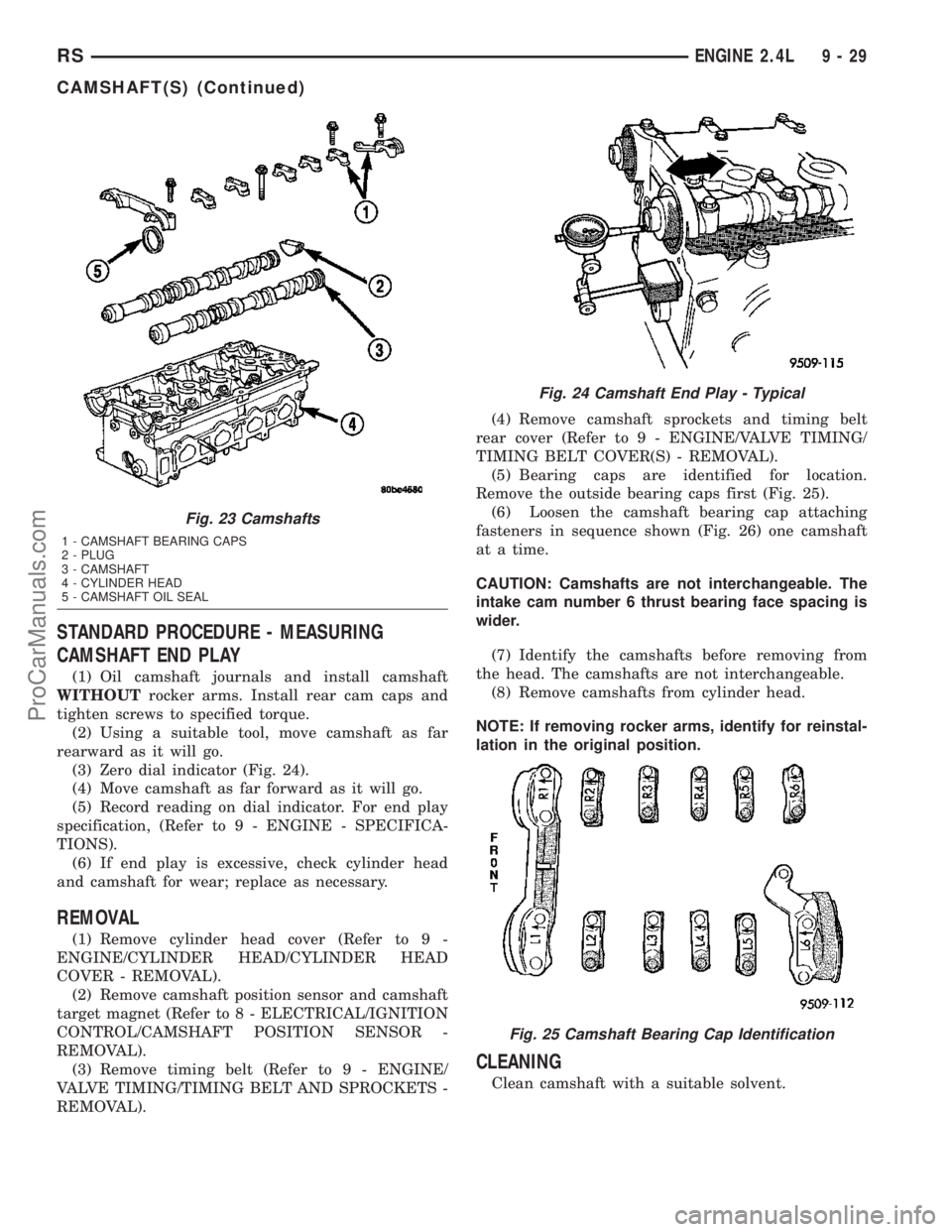
Both camshafts have six bearing journal surfaces
and two cam lobes per cylinder (Fig. 23). Flanges at
the rear journals control camshaft end play. Provision
for a cam position sensor is located on the intake
camshaft on the rear of the cylinder head. A hydro-
dynamic oil seal is used for oil control at the front of
the camshaft.
OPERATION
The camshaft is driven by the crankshaft via drive
sprockets and belt. The camshaft has precisely
machined lobes to provide accurate valve timing and
duration.
Fig. 20 Camshaft Sprocket - Removal/Installation
1 - SPECIAL TOOL 6847
Fig. 21 Camshaft Oil Seal - Removal With C-4679A
1 - SPECIAL TOOL C-4679
Fig. 22 Camshaft Seal - Installation
1 - SPECIAL TOOL MD-998306
9 - 28 ENGINE 2.4LRS
CAMSHAFT OIL SEAL(S) (Continued)
ProCarManuals.com
Page 1208 of 2177
STANDARD PROCEDURE - MEASURING
CAMSHAFT END PLAY
(1) Oil camshaft journals and install camshaft
WITHOUTrocker arms. Install rear cam caps and
tighten screws to specified torque.
(2) Using a suitable tool, move camshaft as far
rearward as it will go.
(3) Zero dial indicator (Fig. 24).
(4) Move camshaft as far forward as it will go.
(5) Record reading on dial indicator. For end play
specification, (Refer to 9 - ENGINE - SPECIFICA-
TIONS).
(6) If end play is excessive, check cylinder head
and camshaft for wear; replace as necessary.
REMOVAL
(1) Remove cylinder head cover (Refer to 9 -
ENGINE/CYLINDER HEAD/CYLINDER HEAD
COVER - REMOVAL).
(2) Remove camshaft position sensor and camshaft
target magnet (Refer to 8 - ELECTRICAL/IGNITION
CONTROL/CAMSHAFT POSITION SENSOR -
REMOVAL).
(3) Remove timing belt (Refer to 9 - ENGINE/
VALVE TIMING/TIMING BELT AND SPROCKETS -
REMOVAL).(4) Remove camshaft sprockets and timing belt
rear cover (Refer to 9 - ENGINE/VALVE TIMING/
TIMING BELT COVER(S) - REMOVAL).
(5) Bearing caps are identified for location.
Remove the outside bearing caps first (Fig. 25).
(6) Loosen the camshaft bearing cap attaching
fasteners in sequence shown (Fig. 26) one camshaft
at a time.
CAUTION: Camshafts are not interchangeable. The
intake cam number 6 thrust bearing face spacing is
wider.
(7) Identify the camshafts before removing from
the head. The camshafts are not interchangeable.
(8) Remove camshafts from cylinder head.
NOTE: If removing rocker arms, identify for reinstal-
lation in the original position.
CLEANING
Clean camshaft with a suitable solvent.
Fig. 23 Camshafts
1 - CAMSHAFT BEARING CAPS
2 - PLUG
3 - CAMSHAFT
4 - CYLINDER HEAD
5 - CAMSHAFT OIL SEAL
Fig. 24 Camshaft End Play - Typical
Fig. 25 Camshaft Bearing Cap Identification
RSENGINE 2.4L9-29
CAMSHAFT(S) (Continued)
ProCarManuals.com
Page 1210 of 2177
(7) Install cylinder head cover (Refer to 9 -
ENGINE/CYLINDER HEAD/CYLINDER HEAD
COVER - INSTALLATION).
(8) Install timing belt rear cover and camshaft
sprockets (Refer to 9 - ENGINE/VALVE TIMING/
TIMING BELT COVER(S) - INSTALLATION).
(9) Install timing belt (Refer to 9 - ENGINE/
VALVE TIMING/TIMING BELT AND SPROCKETS -
INSTALLATION).
CYLINDER HEAD COVER
REMOVAL
(1) Remove upper intake manifold. (Refer to 9 -
ENGINE/MANIFOLDS/INTAKE MANIFOLD -
REMOVAL)
(2) Remove upper manifold support bracket.
(3) Remove ignition coil and spark plug wires.
(4) Disconnect PCV and make-up air hoses from
cylinder head cover.
(5) Remove cylinder head cover bolts.
(6) Remove cylinder head cover from cylinder
head.
CLEANING
Clean cylinder head and cover mating surfaces
using a suitable solvent.
INSPECTION
Inspect cover rails for flatness.
INSTALLATION
NOTE: Replace spark plug well seals and bolt
assemblies when installing a new cylinder head
cover gasket.
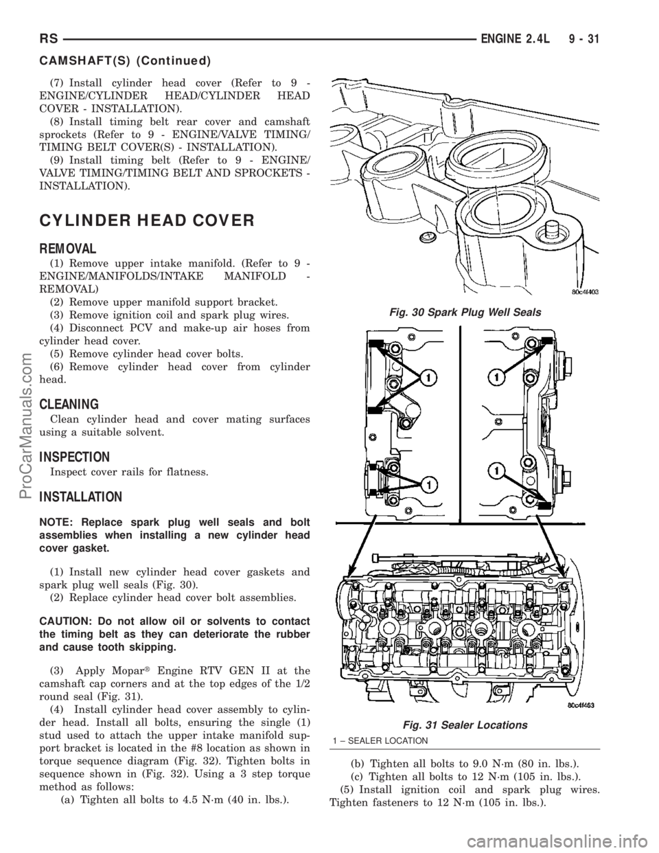
(1) Install new cylinder head cover gaskets and
spark plug well seals (Fig. 30).
(2) Replace cylinder head cover bolt assemblies.
CAUTION: Do not allow oil or solvents to contact
the timing belt as they can deteriorate the rubber
and cause tooth skipping.
(3) Apply MopartEngine RTV GEN II at the
camshaft cap corners and at the top edges of the 1/2
round seal (Fig. 31).
(4) Install cylinder head cover assembly to cylin-
der head. Install all bolts, ensuring the single (1)
stud used to attach the upper intake manifold sup-
port bracket is located in the #8 location as shown in
torque sequence diagram (Fig. 32). Tighten bolts in
sequence shown in (Fig. 32). Using a 3 step torque
method as follows:
(a) Tighten all bolts to 4.5 N´m (40 in. lbs.).(b) Tighten all bolts to 9.0 N´m (80 in. lbs.).
(c) Tighten all bolts to 12 N´m (105 in. lbs.).
(5) Install ignition coil and spark plug wires.
Tighten fasteners to 12 N´m (105 in. lbs.).
Fig. 30 Spark Plug Well Seals
Fig. 31 Sealer Locations
1 ± SEALER LOCATION
RSENGINE 2.4L9-31
CAMSHAFT(S) (Continued)
ProCarManuals.com
Page 1216 of 2177
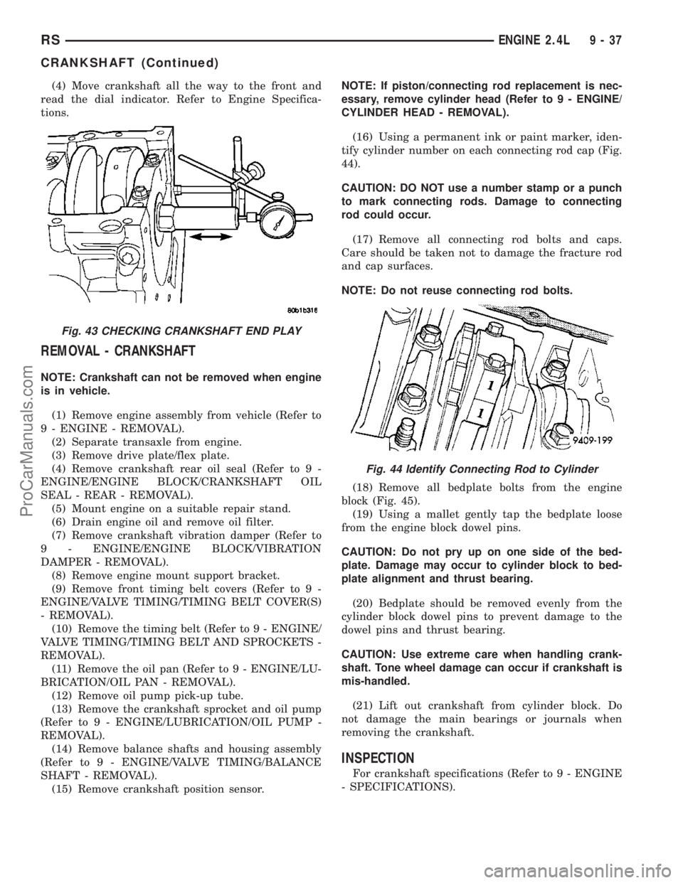
(4) Move crankshaft all the way to the front and
read the dial indicator. Refer to Engine Specifica-
tions.
REMOVAL - CRANKSHAFT
NOTE: Crankshaft can not be removed when engine
is in vehicle.
(1) Remove engine assembly from vehicle (Refer to
9 - ENGINE - REMOVAL).
(2) Separate transaxle from engine.
(3) Remove drive plate/flex plate.
(4) Remove crankshaft rear oil seal (Refer to 9 -
ENGINE/ENGINE BLOCK/CRANKSHAFT OIL
SEAL - REAR - REMOVAL).
(5) Mount engine on a suitable repair stand.
(6) Drain engine oil and remove oil filter.
(7) Remove crankshaft vibration damper (Refer to
9 - ENGINE/ENGINE BLOCK/VIBRATION
DAMPER - REMOVAL).
(8) Remove engine mount support bracket.
(9) Remove front timing belt covers (Refer to 9 -
ENGINE/VALVE TIMING/TIMING BELT COVER(S)
- REMOVAL).
(10) Remove the timing belt (Refer to 9 - ENGINE/
VALVE TIMING/TIMING BELT AND SPROCKETS -
REMOVAL).
(11) Remove the oil pan (Refer to 9 - ENGINE/LU-
BRICATION/OIL PAN - REMOVAL).
(12) Remove oil pump pick-up tube.
(13) Remove the crankshaft sprocket and oil pump
(Refer to 9 - ENGINE/LUBRICATION/OIL PUMP -
REMOVAL).
(14) Remove balance shafts and housing assembly
(Refer to 9 - ENGINE/VALVE TIMING/BALANCE
SHAFT - REMOVAL).
(15) Remove crankshaft position sensor.NOTE: If piston/connecting rod replacement is nec-
essary, remove cylinder head (Refer to 9 - ENGINE/
CYLINDER HEAD - REMOVAL).
(16) Using a permanent ink or paint marker, iden-
tify cylinder number on each connecting rod cap (Fig.
44).
CAUTION: DO NOT use a number stamp or a punch
to mark connecting rods. Damage to connecting
rod could occur.
(17) Remove all connecting rod bolts and caps.
Care should be taken not to damage the fracture rod
and cap surfaces.
NOTE: Do not reuse connecting rod bolts.
(18) Remove all bedplate bolts from the engine
block (Fig. 45).
(19) Using a mallet gently tap the bedplate loose
from the engine block dowel pins.
CAUTION: Do not pry up on one side of the bed-
plate. Damage may occur to cylinder block to bed-
plate alignment and thrust bearing.
(20) Bedplate should be removed evenly from the
cylinder block dowel pins to prevent damage to the
dowel pins and thrust bearing.
CAUTION: Use extreme care when handling crank-
shaft. Tone wheel damage can occur if crankshaft is
mis-handled.
(21) Lift out crankshaft from cylinder block. Do
not damage the main bearings or journals when
removing the crankshaft.
INSPECTION
For crankshaft specifications (Refer to 9 - ENGINE
- SPECIFICATIONS).
Fig. 43 CHECKING CRANKSHAFT END PLAY
Fig. 44 Identify Connecting Rod to Cylinder
RSENGINE 2.4L9-37
CRANKSHAFT (Continued)
ProCarManuals.com
Page 1219 of 2177
(13) After the main bearing bedplate is installed,
check the crankshaft turning torque. The turning
torque should not exceed 5.6 N´m (50 in. lbs.).
(14) Check crankshaft end play (Refer to 9 -
ENGINE/ENGINE BLOCK/CRANKSHAFT - STAN-
DARD PROCEDURE).
(15) Install connecting rod bearings and caps.Do
Not Reuse Connecting Rod Bolts.Torque connect-
ing rod bolts to 27 N´m (20 ft. lbs.) plus 1/4 turn.
(16) Install balance shafts and housing assembly
(Refer to 9 - ENGINE/VALVE TIMING/BALANCE
SHAFT - INSTALLATION).
(17) Install the oil pump (Refer to 9 - ENGINE/
LUBRICATION/OIL PUMP - INSTALLATION).
(18) Install oil pump pick-up tube. Torque fastener
to 28 N´m (20 ft.. lbs.).
(19) Install the oil pan (Refer to 9 - ENGINE/LU-
BRICATION/OIL PAN - INSTALLATION).
(20) Install crankshaft position sensor.
(21) Install cylinder head if it was removed (Refer
to 9 - ENGINE/CYLINDER HEAD - INSTALLA-
TION).
(22) Install the timing belt rear cover (Refer to 9 -
ENGINE/VALVE TIMING/TIMING BELT COVER(S)
- INSTALLATION).
(23) Install crankshaft sprocket (Refer to 9 -
ENGINE/VALVE TIMING/TIMING BELT AND
SPROCKETS - INSTALLATION).
(24) Install the timing belt (Refer to 9 - ENGINE/
VALVE TIMING/TIMING BELT AND SPROCKETS -
INSTALLATION).
(25) Install the timing belt front covers (Refer to 9
- ENGINE/VALVE TIMING/TIMING BELT COV-
ER(S) - INSTALLATION).
(26) Install engine mount support bracket.
(27) InstallNEWoil filter.
(28) Install crankshaft rear oil seal (Refer to 9 -
ENGINE/ENGINE BLOCK/CRANKSHAFT OIL
SEAL - REAR - INSTALLATION).
(29) Install flex plate. Apply MopartLock & Seal
Adhesive to bolt threads and tighten to 95 N´m (70
ft. lbs.).
(30) Attach transaxle to engine. Tighten attaching
bolts to 101 N´m (75 ft. lbs.).
(31) Install the engine assembly (Refer to 9 -
ENGINE - INSTALLATION).
CRANKSHAFT OIL SEAL -
FRONT
REMOVAL
(1) Remove the crankshaft vibration damper.
(Refer to 9 - ENGINE/ENGINE BLOCK/VIBRATION
DAMPER - REMOVAL)(2) Remove timing belt. (Refer to 9 - ENGINE/
VALVE TIMING/TIMING BELT/CHAIN AND
SPROCKETS - REMOVAL)
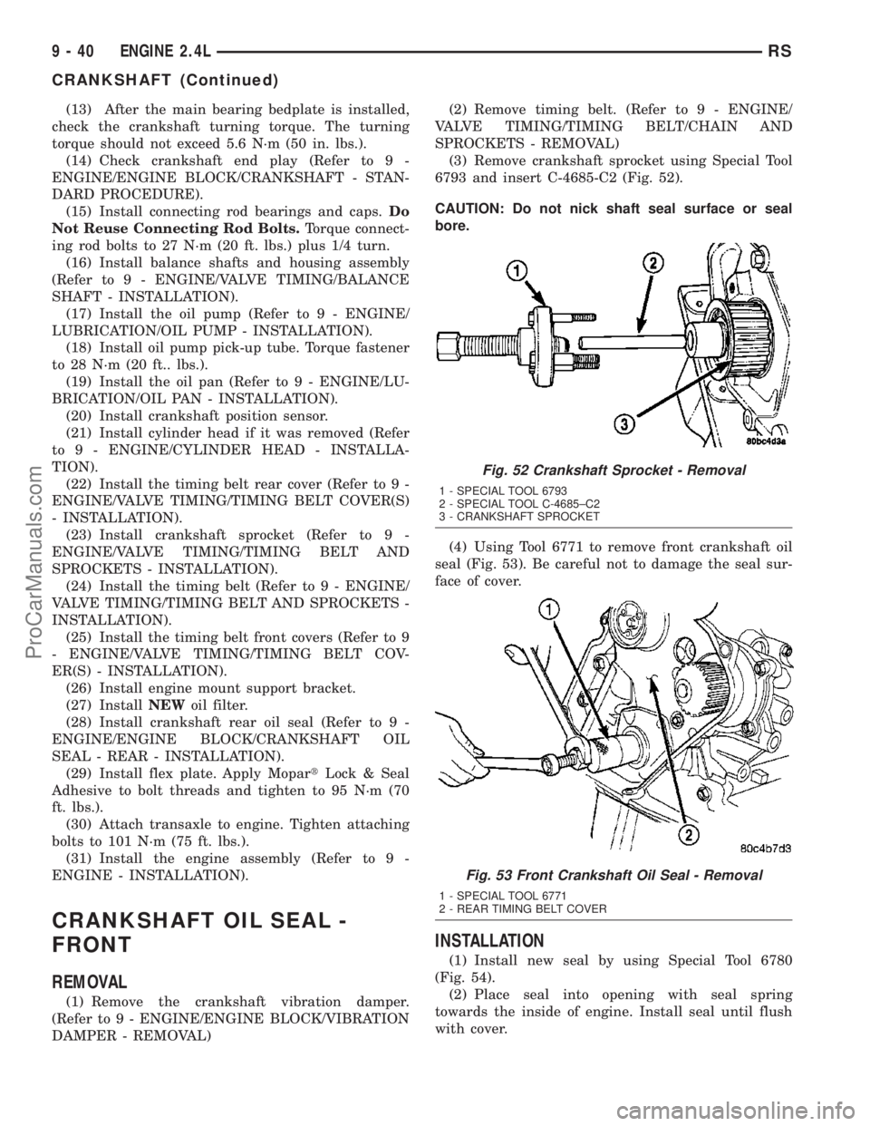
(3) Remove crankshaft sprocket using Special Tool
6793 and insert C-4685-C2 (Fig. 52).
CAUTION: Do not nick shaft seal surface or seal
bore.
(4) Using Tool 6771 to remove front crankshaft oil
seal (Fig. 53). Be careful not to damage the seal sur-
face of cover.
INSTALLATION
(1) Install new seal by using Special Tool 6780
(Fig. 54).
(2) Place seal into opening with seal spring
towards the inside of engine. Install seal until flush
with cover.
Fig. 52 Crankshaft Sprocket - Removal
1 - SPECIAL TOOL 6793
2 - SPECIAL TOOL C-4685±C2
3 - CRANKSHAFT SPROCKET
Fig. 53 Front Crankshaft Oil Seal - Removal
1 - SPECIAL TOOL 6771
2 - REAR TIMING BELT COVER
9 - 40 ENGINE 2.4LRS
CRANKSHAFT (Continued)
ProCarManuals.com
Page 1220 of 2177
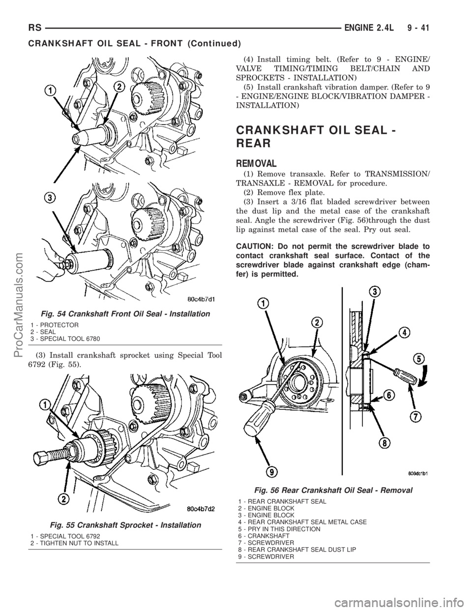
(3) Install crankshaft sprocket using Special Tool
6792 (Fig. 55).(4) Install timing belt. (Refer to 9 - ENGINE/
VALVE TIMING/TIMING BELT/CHAIN AND
SPROCKETS - INSTALLATION)
(5) Install crankshaft vibration damper. (Refer to 9
- ENGINE/ENGINE BLOCK/VIBRATION DAMPER -
INSTALLATION)
CRANKSHAFT OIL SEAL -
REAR
REMOVAL
(1) Remove transaxle. Refer to TRANSMISSION/
TRANSAXLE - REMOVAL for procedure.
(2) Remove flex plate.
(3) Insert a 3/16 flat bladed screwdriver between
the dust lip and the metal case of the crankshaft
seal. Angle the screwdriver (Fig. 56)through the dust
lip against metal case of the seal. Pry out seal.
CAUTION: Do not permit the screwdriver blade to
contact crankshaft seal surface. Contact of the
screwdriver blade against crankshaft edge (cham-
fer) is permitted.
Fig. 54 Crankshaft Front Oil Seal - Installation
1 - PROTECTOR
2 - SEAL
3 - SPECIAL TOOL 6780
Fig. 55 Crankshaft Sprocket - Installation
1 - SPECIAL TOOL 6792
2 - TIGHTEN NUT TO INSTALL
Fig. 56 Rear Crankshaft Oil Seal - Removal
1 - REAR CRANKSHAFT SEAL
2 - ENGINE BLOCK
3 - ENGINE BLOCK
4 - REAR CRANKSHAFT SEAL METAL CASE
5 - PRY IN THIS DIRECTION
6 - CRANKSHAFT
7 - SCREWDRIVER
8 - REAR CRANKSHAFT SEAL DUST LIP
9 - SCREWDRIVER
RSENGINE 2.4L9-41
CRANKSHAFT OIL SEAL - FRONT (Continued)
ProCarManuals.com
Page 1222 of 2177
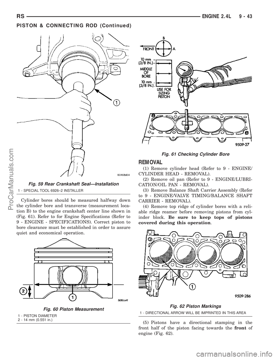
Cylinder bores should be measured halfway down
the cylinder bore and transverse (measurement loca-
tion B) to the engine crankshaft center line shown in
(Fig. 61). Refer to for Engine Specifications (Refer to
9 - ENGINE - SPECIFICATIONS). Correct piston to
bore clearance must be established in order to assure
quiet and economical operation.
REMOVAL
(1) Remove cylinder head (Refer to 9 - ENGINE/
CYLINDER HEAD - REMOVAL).
(2) Remove oil pan (Refer to 9 - ENGINE/LUBRI-
CATION/OIL PAN - REMOVAL).
(3) Remove Balance Shaft Carrier Assembly (Refer
to 9 - ENGINE/VALVE TIMING/BALANCE SHAFT
CARRIER - REMOVAL).
(4) Remove top ridge of cylinder bores with a reli-
able ridge reamer before removing pistons from cyl-
inder block.Be sure to keep tops of pistons
covered during this operation.
(5) Pistons have a directional stamping in the
front half of the piston facing towards thefrontof
engine (Fig. 62).
Fig. 59 Rear Crankshaft SealÐInstallation
1 - SPECIAL TOOL 6926±2 INSTALLER
Fig. 60 Piston Measurement
1 - PISTON DIAMETER
2 - 14 mm (0.551 in.)
Fig. 61 Checking Cylinder Bore
Fig. 62 Piston Markings
1 - DIRECTIONAL ARROW WILL BE IMPRINTED IN THIS AREA
RSENGINE 2.4L9-43
PISTON & CONNECTING ROD (Continued)
ProCarManuals.com
Page 1224 of 2177
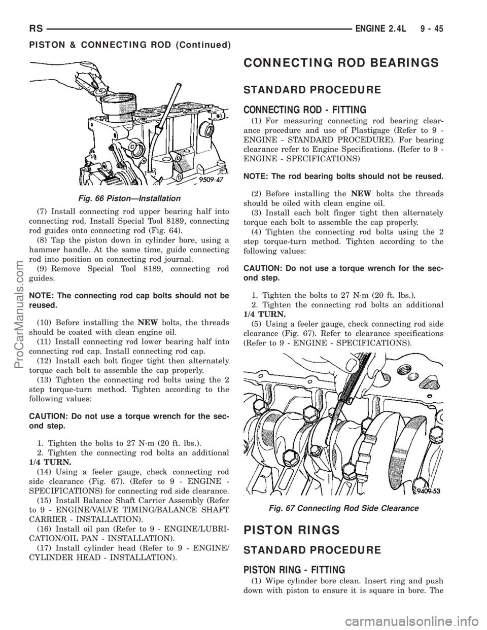
(7) Install connecting rod upper bearing half into
connecting rod. Install Special Tool 8189, connecting
rod guides onto connecting rod (Fig. 64).
(8) Tap the piston down in cylinder bore, using a
hammer handle. At the same time, guide connecting
rod into position on connecting rod journal.
(9) Remove Special Tool 8189, connecting rod
guides.
NOTE: The connecting rod cap bolts should not be
reused.
(10) Before installing theNEWbolts, the threads
should be coated with clean engine oil.
(11) Install connecting rod lower bearing half into
connecting rod cap. Install connecting rod cap.
(12) Install each bolt finger tight then alternately
torque each bolt to assemble the cap properly.
(13) Tighten the connecting rod bolts using the 2
step torque-turn method. Tighten according to the
following values:
CAUTION: Do not use a torque wrench for the sec-
ond step.
1. Tighten the bolts to 27 N´m (20 ft. lbs.).
2. Tighten the connecting rod bolts an additional
1/4 TURN.
(14) Using a feeler gauge, check connecting rod
side clearance (Fig. 67). (Refer to 9 - ENGINE -
SPECIFICATIONS) for connecting rod side clearance.
(15) Install Balance Shaft Carrier Assembly (Refer
to 9 - ENGINE/VALVE TIMING/BALANCE SHAFT
CARRIER - INSTALLATION).
(16) Install oil pan (Refer to 9 - ENGINE/LUBRI-
CATION/OIL PAN - INSTALLATION).
(17) Install cylinder head (Refer to 9 - ENGINE/
CYLINDER HEAD - INSTALLATION).
CONNECTING ROD BEARINGS
STANDARD PROCEDURE
CONNECTING ROD - FITTING
(1) For measuring connecting rod bearing clear-
ance procedure and use of Plastigage (Refer to 9 -
ENGINE - STANDARD PROCEDURE). For bearing
clearance refer to Engine Specifications. (Refer to 9 -
ENGINE - SPECIFICATIONS)
NOTE: The rod bearing bolts should not be reused.
(2) Before installing theNEWbolts the threads
should be oiled with clean engine oil.
(3) Install each bolt finger tight then alternately
torque each bolt to assemble the cap properly.
(4) Tighten the connecting rod bolts using the 2
step torque-turn method. Tighten according to the
following values:
CAUTION: Do not use a torque wrench for the sec-
ond step.
1. Tighten the bolts to 27 N´m (20 ft. lbs.).
2. Tighten the connecting rod bolts an additional
1/4 TURN.
(5) Using a feeler gauge, check connecting rod side
clearance (Fig. 67). Refer to clearance specifications
(Refer to 9 - ENGINE - SPECIFICATIONS).
PISTON RINGS
STANDARD PROCEDURE
PISTON RING - FITTING
(1) Wipe cylinder bore clean. Insert ring and push
down with piston to ensure it is square in bore. The
Fig. 66 PistonÐInstallation
Fig. 67 Connecting Rod Side Clearance
RSENGINE 2.4L9-45
PISTON & CONNECTING ROD (Continued)
ProCarManuals.com