2003 CHRYSLER VOYAGER Engine timing
[x] Cancel search: Engine timingPage 1181 of 2177
REMOVAL - CYLINDER HEAD OFF........32
INSPECTION..........................32
INSTALLATION
INSTALLATION - CYLINDER HEAD ON.....33
INSTALLATION - CYLINDER HEAD OFF....33
HYDRAULIC LASH ADJUSTERS
DIAGNOSIS AND TESTING - HYDRAULIC
LASH ADJUSTER NOISE DIAGNOSIS......34
REMOVAL.............................34
INSTALLATION.........................34
ROCKER ARMS
REMOVAL.............................34
INSPECTION..........................35
INSTALLATION.........................35
ENGINE BLOCK
DESCRIPTION.........................35
STANDARD PROCEDURE - CYLINDER BORE
HONING............................35
CLEANING............................36
INSPECTION..........................36
CRANKSHAFT
STANDARD PROCEDURE - CRANKSHAFT
ENDPLAY ...........................36
REMOVAL - CRANKSHAFT................37
INSPECTION..........................37
INSTALLATION - CRANKSHAFT............38
CRANKSHAFT OIL SEAL - FRONT
REMOVAL.............................40
INSTALLATION.........................40
CRANKSHAFT OIL SEAL - REAR
REMOVAL.............................41
INSTALLATION.........................42
PISTON & CONNECTING ROD
DESCRIPTION.........................42
STANDARD PROCEDURE - PISTON TO
CYLINDER BORE FITTING..............42
REMOVAL.............................43
INSTALLATION.........................44
CONNECTING ROD BEARINGS
STANDARD PROCEDURE
CONNECTING ROD - FITTING...........45
PISTON RINGS
STANDARD PROCEDURE
PISTON RING - FITTING................45
REMOVAL.............................46
INSTALLATION.........................46
VIBRATION DAMPER
REMOVAL.............................47
INSTALLATION.........................47
STRUCTURAL COLLAR
REMOVAL.............................47
INSTALLATION.........................48
ENGINE MOUNTING
DESCRIPTION.........................48
FRONT MOUNT
REMOVAL.............................49
INSTALLATION.........................49LEFT MOUNT
REMOVAL.............................49
INSTALLATION.........................50
REAR MOUNT
REMOVAL.............................50
INSTALLATION.........................50
RIGHT MOUNT
REMOVAL.............................51
INSTALLATION.........................51
LUBRICATION
DESCRIPTION.........................52
OPERATION...........................52
DIAGNOSIS AND TESTING - CHECKING
ENGINE OIL PRESSURE................52
OIL
STANDARD PROCEDURE
ENGINE OIL LEVEL CHECK.............53
STANDARD PROCEDURE - ENGINE OIL
AND FILTER CHANGE..................53
OIL FILTER
DESCRIPTION.........................53
REMOVAL.............................53
INSTALLATION.........................53
OIL PAN
REMOVAL.............................54
INSTALLATION.........................54
OIL PRESSURE SWITCH
REMOVAL.............................54
INSTALLATION.........................54
OIL PUMP
REMOVAL.............................55
DISASSEMBLY.........................55
CLEANING............................56
INSPECTION..........................56
ASSEMBLY............................56
INSTALLATION.........................57
INTAKE MANIFOLD
DESCRIPTION.........................58
DIAGNOSIS AND TESTING - INTAKE
MANIFOLD LEAKS.....................58
INTAKE MANIFOLD - UPPER
REMOVAL.............................58
INSPECTION..........................59
INSTALLATION.........................59
INTAKE MANIFOLD - LOWER
REMOVAL.............................60
INSPECTION..........................60
INSTALLATION.........................60
EXHAUST MANIFOLD
REMOVAL.............................61
CLEANING............................61
INSPECTION..........................61
INSTALLATION.........................61
TIMING BELT COVER(S)
REMOVAL.............................61
INSTALLATION.........................62
9 - 2 ENGINE 2.4LRS
ProCarManuals.com
Page 1182 of 2177
TIMING BELT AND SPROCKET(S)
REMOVAL
REMOVAL - TIMING BELT...............63
REMOVAL - CAMSHAFT SPROCKETS.....64
REMOVAL - CRANKSHAFT SPROCKET....64
CLEANING............................64
INSTALLATION
INSTALLATION - CRANKSHAFT SPROCKET . 65
INSTALLATION - CAMSHAFT SPROCKETS . . 65INSTALLATION - TIMING BELT...........65
TIMING BELT TENSIONER & PULLEY
REMOVAL.............................68
INSTALLATION.........................69
BALANCE SHAFTS AND CARRIER ASSEMBLY
DESCRIPTION.........................69
OPERATION...........................69
REMOVAL.............................69
INSTALLATION.........................72
ENGINE 2.4L
DESCRIPTION
The 2.4 Liter (148 cu. in.) in-line four cylinder
engine is a double over head camshaft with hydraulic
lash adjusters and four valve per cylinder design.
The engine is free-wheeling; meaning it has provi-
sions for piston-to-valve clearance. However valve-to-
valve interference can occur, if camshafts are rotated
independently.
The cylinders are numbered from front of the
engine to the rear. The firing order is 1±3±4±2.
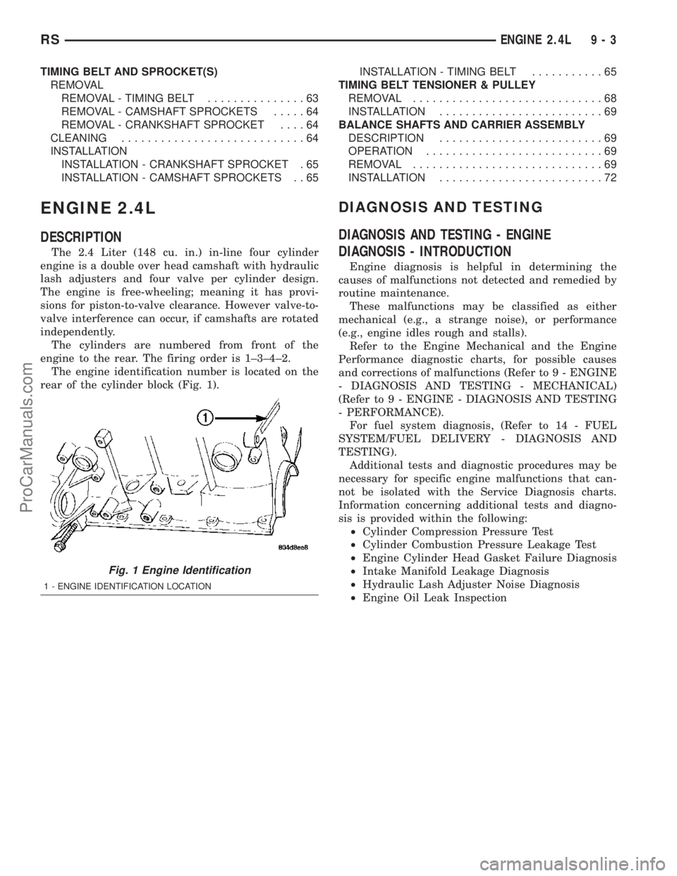
The engine identification number is located on the
rear of the cylinder block (Fig. 1).
DIAGNOSIS AND TESTING
DIAGNOSIS AND TESTING - ENGINE
DIAGNOSIS - INTRODUCTION
Engine diagnosis is helpful in determining the
causes of malfunctions not detected and remedied by
routine maintenance.
These malfunctions may be classified as either
mechanical (e.g., a strange noise), or performance
(e.g., engine idles rough and stalls).
Refer to the Engine Mechanical and the Engine
Performance diagnostic charts, for possible causes
and corrections of malfunctions (Refer to 9 - ENGINE
- DIAGNOSIS AND TESTING - MECHANICAL)
(Refer to 9 - ENGINE - DIAGNOSIS AND TESTING
- PERFORMANCE).
For fuel system diagnosis, (Refer to 14 - FUEL
SYSTEM/FUEL DELIVERY - DIAGNOSIS AND
TESTING).
Additional tests and diagnostic procedures may be
necessary for specific engine malfunctions that can-
not be isolated with the Service Diagnosis charts.
Information concerning additional tests and diagno-
sis is provided within the following:
²Cylinder Compression Pressure Test
²Cylinder Combustion Pressure Leakage Test
²Engine Cylinder Head Gasket Failure Diagnosis
²Intake Manifold Leakage Diagnosis
²Hydraulic Lash Adjuster Noise Diagnosis
²Engine Oil Leak Inspection
Fig. 1 Engine Identification
1 - ENGINE IDENTIFICATION LOCATION
RSENGINE 2.4L9-3
ProCarManuals.com
Page 1183 of 2177
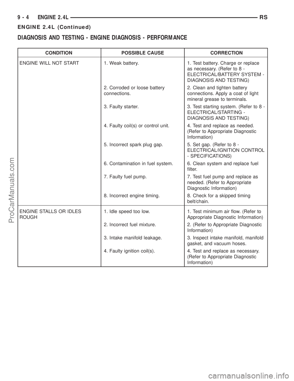
DIAGNOSIS AND TESTING - ENGINE DIAGNOSIS - PERFORMANCE
CONDITION POSSIBLE CAUSE CORRECTION
ENGINE WILL NOT START 1. Weak battery. 1. Test battery. Charge or replace
as necessary. (Refer to 8 -
ELECTRICAL/BATTERY SYSTEM -
DIAGNOSIS AND TESTING)
2. Corroded or loose battery
connections.2. Clean and tighten battery
connections. Apply a coat of light
mineral grease to terminals.
3. Faulty starter. 3. Test starting system. (Refer to 8 -
ELECTRICAL/STARTING -
DIAGNOSIS AND TESTING)
4. Faulty coil(s) or control unit. 4. Test and replace as needed.
(Refer to Appropriate Diagnostic
Information)
5. Incorrect spark plug gap. 5. Set gap. (Refer to 8 -
ELECTRICAL/IGNITION CONTROL
- SPECIFICATIONS)
6. Contamination in fuel system. 6. Clean system and replace fuel
filter.
7. Faulty fuel pump. 7. Test fuel pump and replace as
needed. (Refer to Appropriate
Diagnostic Information)
8. Incorrect engine timing. 8. Check for a skipped timing
belt/chain.
ENGINE STALLS OR IDLES
ROUGH1. Idle speed too low. 1. Test minimum air flow. (Refer to
Appropriate Diagnostic Information)
2. Incorrect fuel mixture. 2. (Refer to Appropriate Diagnostic
Information)
3. Intake manifold leakage. 3. Inspect intake manifold, manifold
gasket, and vacuum hoses.
4. Faulty ignition coil(s). 4. Test and replace as necessary.
(Refer to Appropriate Diagnostic
Information)
9 - 4 ENGINE 2.4LRS
ENGINE 2.4L (Continued)
ProCarManuals.com
Page 1184 of 2177
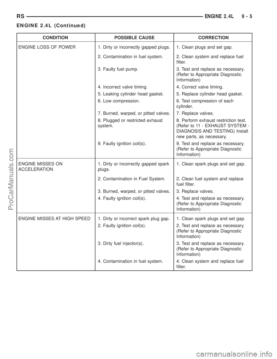
CONDITION POSSIBLE CAUSE CORRECTION
ENGINE LOSS OF POWER 1. Dirty or incorrectly gapped plugs. 1. Clean plugs and set gap.
2. Contamination in fuel system. 2. Clean system and replace fuel
filter.
3. Faulty fuel pump. 3. Test and replace as necessary.
(Refer to Appropriate Diagnostic
Information)
4. Incorrect valve timing. 4. Correct valve timing.
5. Leaking cylinder head gasket. 5. Replace cylinder head gasket.
6. Low compression. 6. Test compression of each
cylinder.
7. Burned, warped, or pitted valves. 7. Replace valves.
8. Plugged or restricted exhaust
system.8. Perform exhaust restriction test.
(Refer to 11 - EXHAUST SYSTEM -
DIAGNOSIS AND TESTING) Install
new parts, as necessary.
9. Faulty ignition coil(s). 9. Test and replace as necessary.
(Refer to Appropriate Diagnostic
Information)
ENGINE MISSES ON
ACCELERATION1. Dirty or incorrectly gapped spark
plugs.1. Clean spark plugs and set gap.
2. Contamination in Fuel System. 2. Clean fuel system and replace
fuel filter.
3. Burned, warped, or pitted valves. 3. Replace valves.
4. Faulty ignition coil(s). 4. Test and replace as necessary.
(Refer to Appropriate Diagnostic
Information)
ENGINE MISSES AT HIGH SPEED 1. Dirty or incorrect spark plug gap. 1. Clean spark plugs and set gap.
2. Faulty ignition coil(s). 2. Test and replace as necessary.
(Refer to Appropriate Diagnostic
Information)
3. Dirty fuel injector(s). 3. Test and replace as necessary.
(Refer to Appropriate Diagnostic
Information)
4. Contamination in fuel system. 4. Clean system and replace fuel
filter.
RSENGINE 2.4L9-5
ENGINE 2.4L (Continued)
ProCarManuals.com
Page 1197 of 2177
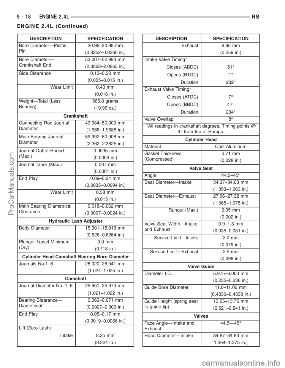
DESCRIPTION SPECIFICATION
Bore DiameterÐPiston
Pin20.96±20.98 mm
(0.8252±0.8260 in.)
Bore DiameterÐ
Crankshaft End53.007±52.993 mm
(2.0868±2.0863 in.)
Side Clearance 0.13±0.38 mm
(0.005±0.015 in.)
Wear Limit 0.40 mm
(0.016 in.)
WeightÐTotal (Less
Bearing)565.8 grams
(19.96 oz.)
Crankshaft
Connecting Rod Journal
Diameter49.984±50.000 mm
(1.968±1.9685 in.)
Main Bearing Journal
Diameter59.992±60.008 mm
(2.362±2.3625 in.)
Journal Out-of-Round
(Max.)0.0035 mm
(0.0003 in.)
Journal Taper (Max.) 0.007 mm
(0.0001 in.)
End Play 0.09±0.24 mm
(0.0035±0.0094 in.)
Wear Limit 0.38 mm
(0.015 in.)
Main Bearing Diametrical
Clearance0.018±0.062 mm
(0.0007±0.0024 in.)
Hydraulic Lash Adjuster
Body Diameter 15.901±15.913 mm
(0.626±0.6264 in.)
Plunger Travel Minimum
(Dry)3.0 mm
(0.118 in.)
Cylinder Head Camshaft Bearing Bore Diameter
Journals No.1±6 26.020±26.041 mm
(1.024±1.025 in.)
Camshaft
Journal Diameter No. 1±6 25.951±25.970 mm
(1.021±1.022 in.)
Bearing ClearanceÐ
Diametrical0.069±0.071 mm
(0.0027±0.003 in.)
End Play 0.05±0.17 mm
(0.0019±0.0066 in.)
Lift (Zero Lash)
Intake 8.25 mm
(0.324 in.)DESCRIPTION SPECIFICATION
Exhaust 6.60 mm
(0.259 in.)
Intake Valve Timing*
Closes (ABDC) 51É
Opens (BTDC) 1É
Duration 232É
Exhaust Valve Timing*
Closes (ATDC) 7É
Opens (BBDC) 47É
Duration 234É
Valve Overlap 8É
*All readings in crankshaft degrees. Timing points @
4É from top of Ramps.
Cylinder Head
Material Cast Aluminum
Gasket Thickness
(Compressed)0.71 mm
(0.028 in.)
Valve Seat
Angle 44.5±45É
Seat DiameterÐIntake 34.37±34.63 mm
(1.353±1.363 in.)
Seat DiameterÐExhaust 27.06±27.32 mm
(1.065±1.075 in.)
Runout (Max.) 0.05 mm
(0.002 in.)
Valve Seat WidthÐIntake
and Exhaust0.9±1.3 mm
(0.035±0.051 in.)
Service LimitÐIntake 2.0 mm
(0.079 in.)
Service LimitÐExhaust 2.5 mm
(0.098 in.)
Valve Guide
Diameter I.D. 5.975±6.000 mm
(0.235±0.236 in.)
Guide Bore Diameter 11.0±11.02 mm
(0.4330±0.4338 in.)
Guide Height (spring seat
to guide tip)13.25±13.75 mm
(0.521±0.541 in.)
Valves
Face AngleÐIntake and
Exhaust44.5Ð45É
Head DiameterÐIntake 34.67±34.93 mm
1.364±1.375 in.)
9 - 18 ENGINE 2.4LRS
ENGINE 2.4L (Continued)
ProCarManuals.com
Page 1199 of 2177
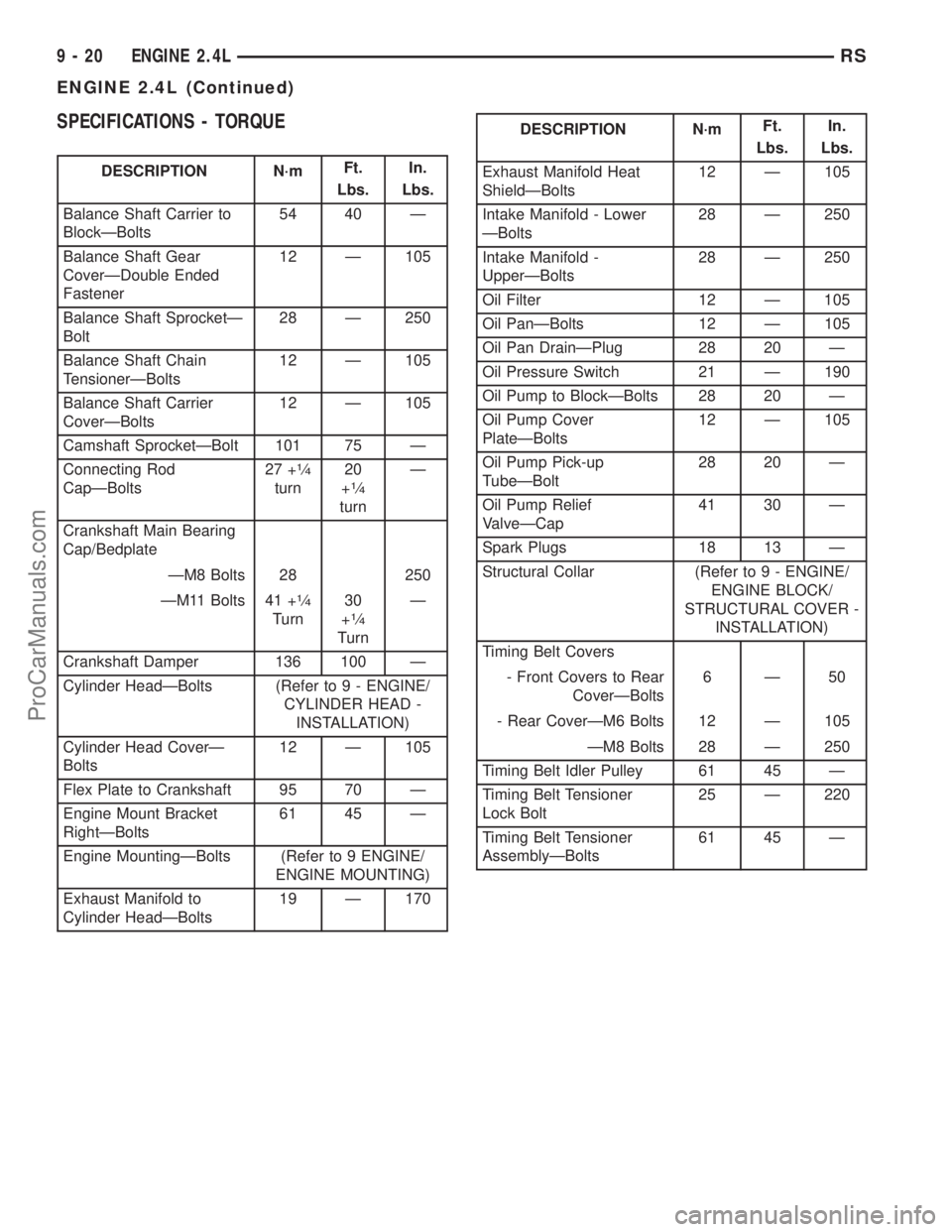
SPECIFICATIONS - TORQUE
DESCRIPTION N´mFt.
Lbs.In.
Lbs.
Balance Shaft Carrier to
BlockÐBolts54 40 Ð
Balance Shaft Gear
CoverÐDouble Ended
Fastener12 Ð 105
Balance Shaft SprocketÐ
Bolt28 Ð 250
Balance Shaft Chain
TensionerÐBolts12 Ð 105
Balance Shaft Carrier
CoverÐBolts12 Ð 105
Camshaft SprocketÐBolt 101 75 Ð
Connecting Rod
CapÐBolts27 +
1¤4
turn20
+1¤4
turnÐ
Crankshaft Main Bearing
Cap/Bedplate
ÐM8 Bolts 28 250
ÐM11 Bolts 41 +
1¤4
Turn30
+1¤4
TurnÐ
Crankshaft Damper 136 100 Ð
Cylinder HeadÐBolts (Refer to 9 - ENGINE/
CYLINDER HEAD -
INSTALLATION)
Cylinder Head CoverÐ
Bolts12 Ð 105
Flex Plate to Crankshaft 95 70 Ð
Engine Mount Bracket
RightÐBolts61 45 Ð
Engine MountingÐBolts (Refer to 9 ENGINE/
ENGINE MOUNTING)
Exhaust Manifold to
Cylinder HeadÐBolts19 Ð 170
DESCRIPTION N´mFt.
Lbs.In.
Lbs.
Exhaust Manifold Heat
ShieldÐBolts12 Ð 105
Intake Manifold - Lower
ÐBolts28 Ð 250
Intake Manifold -
UpperÐBolts28 Ð 250
Oil Filter 12 Ð 105
Oil PanÐBolts 12 Ð 105
Oil Pan DrainÐPlug 28 20 Ð
Oil Pressure Switch 21 Ð 190
Oil Pump to BlockÐBolts 28 20 Ð
Oil Pump Cover
PlateÐBolts12 Ð 105
Oil Pump Pick-up
TubeÐBolt28 20 Ð
Oil Pump Relief
ValveÐCap41 30 Ð
Spark Plugs 18 13 Ð
Structural Collar (Refer to 9 - ENGINE/
ENGINE BLOCK/
STRUCTURAL COVER -
INSTALLATION)
Timing Belt Covers
- Front Covers to Rear
CoverÐBolts6Ð50
- Rear CoverÐM6 Bolts 12 Ð 105
ÐM8 Bolts 28 Ð 250
Timing Belt Idler Pulley 61 45 Ð
Timing Belt Tensioner
Lock Bolt25 Ð 220
Timing Belt Tensioner
AssemblyÐBolts61 45 Ð
9 - 20 ENGINE 2.4LRS
ENGINE 2.4L (Continued)
ProCarManuals.com
Page 1204 of 2177
²Excessive steam (white smoke) emitting from
exhaust
²Coolant foaming
CYLINDER-TO-CYLINDER LEAKAGE TEST
To determine if an engine cylinder head gasket is
leaking between adjacent cylinders, follow the proce-
dures in Cylinder Compression Pressure Test (Refer
to 9 - ENGINE - DIAGNOSIS AND TESTING). An
engine cylinder head gasket leaking between adja-
cent cylinders will result in approximately a 50±70%
reduction in compression pressure.
CYLINDER-TO-WATER JACKET LEAKAGE TEST
WARNING: USE EXTREME CAUTION WHEN THE
ENGINE IS OPERATING WITH COOLANT PRES-
SURE CAP REMOVED.
VISUAL TEST METHOD
With the engine cool, remove the coolant pressure
cap. Start the engine and allow it to warm up until
thermostat opens.
If a large combustion/compression pressure leak
exists, bubbles will be visible in the coolant.COOLING SYSTEM TESTER METHOD
WARNING: WITH COOLING SYSTEM TESTER IN
PLACE, PRESSURE WILL BUILD UP FAST. EXCES-
SIVE PRESSURE BUILT UP, BY CONTINUOUS
ENGINE OPERATION, MUST BE RELEASED TO A
SAFE PRESSURE POINT. NEVER PERMIT PRES-
SURE TO EXCEED 138 kPa (20 psi).
Install Cooling System Tester 7700 or equivalent to
pressure cap neck. Start the engine and observe the
tester's pressure gauge. If gauge pulsates with every
power stroke of a cylinder a combustion pressure
leak is evident.
CHEMICAL TEST METHOD
Combustion leaks into the cooling system can also
be checked by using Bloc-Chek Kit C-3685-A or
equivalent. Perform test following the procedures
supplied with the tool kit.
REMOVAL - CYLINDER HEAD
(1) Perform fuel system pressure release procedure
before attempting any repairs.(Refer to 14 -
FUEL SYSTEM/FUEL DELIVERY - SPECIFICA-
TIONS)
(2) Disconnect battery negative cable.
(3) Drain cooling system. (Refer to 7 - COOLING -
STANDARD PROCEDURE)
(4) Remove air filter housing and inlet tube.
(5) Remove upper intake manifold. (Refer to 9 -
ENGINE/MANIFOLDS/INTAKE MANIFOLD -
REMOVAL)
(6) Remove heater tube support bracket from cyl-
inder head.
(7) Disconnect radiator upper and heater supply
hoses from intake manifold water outlet connections.
(8) Remove accessory drive belts. (Refer to 7 -
COOLING/ACCESSORY DRIVE/DRIVE BELTS -
REMOVAL)
(9) Raise vehicle and remove exhaust pipe from
manifold.
(10) Remove power steering pump reservoir and
line support bracket from lower intake manifold and
set aside. Do not disconnect lines.
(11) Remove ignition coil and wires from engine.
(12) Disconnect cam sensor and fuel injector wir-
ing connectors.
(13) Remove timing belt and camshaft sprockets.
(Refer to 9 - ENGINE/VALVE TIMING/TIMING
BELT/CHAIN AND SPROCKETS - REMOVAL)
(14) Remove timing belt idler pulley and rear tim-
ing belt cover. (Refer to 9 - ENGINE/VALVE TIM-
ING/TIMING BELT / CHAIN COVER(S) -
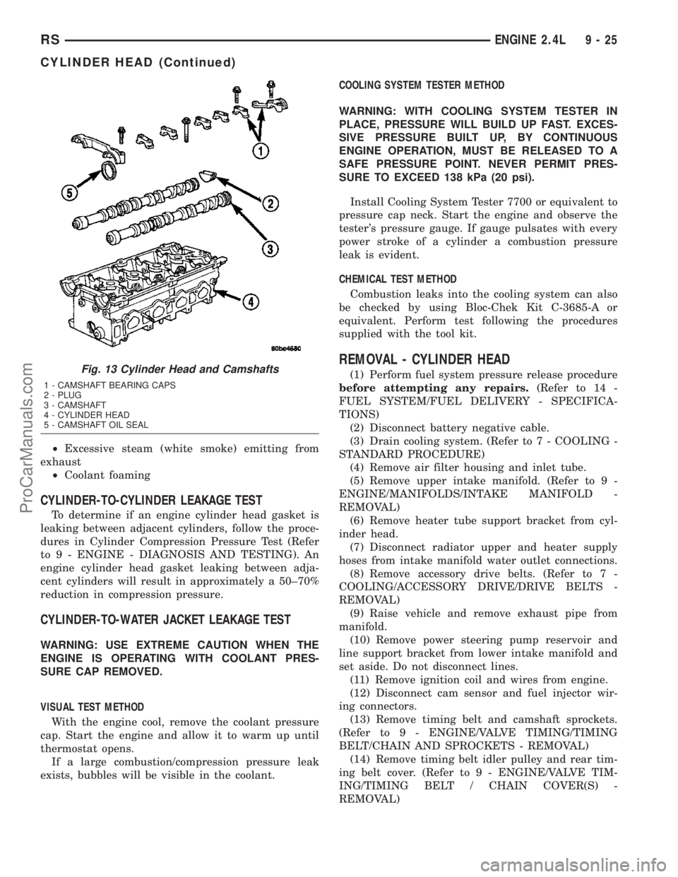
REMOVAL)Fig. 13 Cylinder Head and Camshafts
1 - CAMSHAFT BEARING CAPS
2 - PLUG
3 - CAMSHAFT
4 - CYLINDER HEAD
5 - CAMSHAFT OIL SEAL
RSENGINE 2.4L9-25
CYLINDER HEAD (Continued)
ProCarManuals.com
Page 1206 of 2177
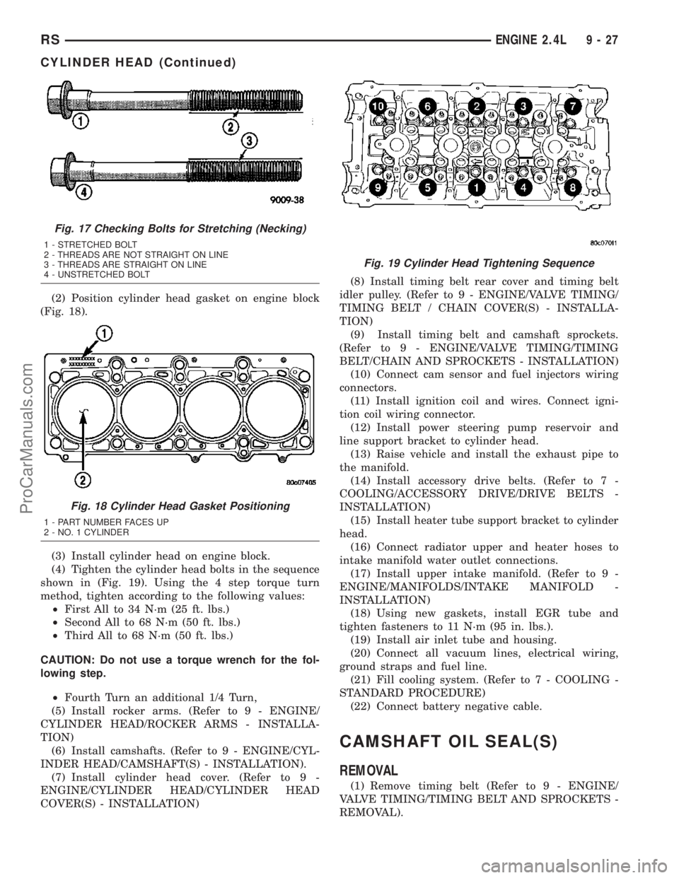
(2) Position cylinder head gasket on engine block
(Fig. 18).
(3) Install cylinder head on engine block.
(4) Tighten the cylinder head bolts in the sequence
shown in (Fig. 19). Using the 4 step torque turn
method, tighten according to the following values:
²First All to 34 N´m (25 ft. lbs.)
²Second All to 68 N´m (50 ft. lbs.)
²Third All to 68 N´m (50 ft. lbs.)
CAUTION: Do not use a torque wrench for the fol-
lowing step.
²Fourth Turn an additional 1/4 Turn,
(5) Install rocker arms. (Refer to 9 - ENGINE/
CYLINDER HEAD/ROCKER ARMS - INSTALLA-
TION)
(6) Install camshafts. (Refer to 9 - ENGINE/CYL-
INDER HEAD/CAMSHAFT(S) - INSTALLATION).
(7) Install cylinder head cover. (Refer to 9 -
ENGINE/CYLINDER HEAD/CYLINDER HEAD
COVER(S) - INSTALLATION)(8) Install timing belt rear cover and timing belt
idler pulley. (Refer to 9 - ENGINE/VALVE TIMING/
TIMING BELT / CHAIN COVER(S) - INSTALLA-
TION)
(9) Install timing belt and camshaft sprockets.
(Refer to 9 - ENGINE/VALVE TIMING/TIMING
BELT/CHAIN AND SPROCKETS - INSTALLATION)
(10) Connect cam sensor and fuel injectors wiring
connectors.
(11) Install ignition coil and wires. Connect igni-
tion coil wiring connector.
(12) Install power steering pump reservoir and
line support bracket to cylinder head.
(13) Raise vehicle and install the exhaust pipe to
the manifold.
(14) Install accessory drive belts. (Refer to 7 -
COOLING/ACCESSORY DRIVE/DRIVE BELTS -
INSTALLATION)
(15) Install heater tube support bracket to cylinder
head.
(16) Connect radiator upper and heater hoses to
intake manifold water outlet connections.
(17) Install upper intake manifold. (Refer to 9 -
ENGINE/MANIFOLDS/INTAKE MANIFOLD -
INSTALLATION)
(18) Using new gaskets, install EGR tube and
tighten fasteners to 11 N´m (95 in. lbs.).
(19) Install air inlet tube and housing.
(20) Connect all vacuum lines, electrical wiring,
ground straps and fuel line.
(21) Fill cooling system. (Refer to 7 - COOLING -
STANDARD PROCEDURE)
(22) Connect battery negative cable.
CAMSHAFT OIL SEAL(S)
REMOVAL
(1) Remove timing belt (Refer to 9 - ENGINE/
VALVE TIMING/TIMING BELT AND SPROCKETS -
REMOVAL).
Fig. 17 Checking Bolts for Stretching (Necking)
1 - STRETCHED BOLT
2 - THREADS ARE NOT STRAIGHT ON LINE
3 - THREADS ARE STRAIGHT ON LINE
4 - UNSTRETCHED BOLT
Fig. 18 Cylinder Head Gasket Positioning
1 - PART NUMBER FACES UP
2 - NO. 1 CYLINDER
Fig. 19 Cylinder Head Tightening Sequence
RSENGINE 2.4L9-27
CYLINDER HEAD (Continued)
ProCarManuals.com