2003 CHRYSLER VOYAGER Windows
[x] Cancel search: WindowsPage 1735 of 2177
DIAGNOSIS AND TESTING
DIAGNOSIS AND TESTING - WATER LEAKS
Water leaks can be caused by poor sealing,
improper body component alignment, body seam
porosity, missing plugs, or blocked drain holes. Cen-
trifugal and gravitational force can cause water to
drip from a location away from the actual leak point,
making leak detection difficult. All body sealing
points should be water tight in normal wet-driving
conditions. Water flowing downward from the front of
the vehicle should not enter the passenger or luggage
compartment. Moving sealing surfaces will not
always seal water tight under all conditions. At
times, side glass or door seals will allow water to
enter the passenger compartment during high pres-
sure washing or hard driving rain (severe) condi-
tions. Overcompensating on door or glass
adjustments to stop a water leak that occurs under
severe conditions can cause premature seal wear and
excessive closing or latching effort. After completing
a repair, water test vehicle to verify leak has stopped
before returning vehicle to use.
VISUAL INSPECTION BEFORE WATER LEAK TESTS
Verify that floor and body plugs are in place, body
drains are clear, and body components are properly
aligned and sealed. If component alignment or seal-
ing is necessary, refer to the appropriate section of
this group for proper procedures.
WATER LEAK TESTS
WARNING: DO NOT USE ELECTRIC SHOP LIGHTS
OR TOOLS IN WATER TEST AREA. PERSONAL
INJURY CAN RESULT.
When the conditions causing a water leak have
been determined, simulate the conditions as closely
as possible.
²If a leak occurs with the vehicle parked in a
steady light rain, flood the leak area with an open-
ended garden hose.
²If a leak occurs while driving at highway speeds
in a steady rain, test the leak area with a reasonable
velocity stream or fan spray of water. Direct the
spray in a direction comparable to actual conditions.
²If a leak occurs when the vehicle is parked on an
incline, hoist the end or side of the vehicle to simu-
late this condition. This method can be used when
the leak occurs when the vehicle accelerates, stops or
turns. If the leak occurs on acceleration, hoist the
front of the vehicle. If the leak occurs when braking,
hoist the back of the vehicle. If the leak occurs on left
turns, hoist the left side of the vehicle. If the leak
occurs on right turns, hoist the right side of the vehi-cle. For hoisting recommendations (Refer to LUBRI-
CATION & MAINTENANCE/HOISTING -
STANDARD PROCEDURE).
WATER LEAK DETECTION
To detect a water leak point-of-entry, do a water
test and watch for water tracks or droplets forming
on the inside of the vehicle. If necessary, remove inte-
rior trim covers or panels to gain visual access to the
leak area. If the hose cannot be positioned without
being held, have someone help do the water test.
Some water leaks must be tested for a considerable
length of time to become apparent. When a leak
appears, find the highest point of the water track or
drop. The highest point usually will show the point of
entry. After leak point has been found, repair the
leak and water test to verify that the leak has
stopped.
Locating the entry point of water that is leaking
into a cavity between panels can be difficult. The
trapped water may splash or run from the cavity,
often at a distance from the entry point. Most water
leaks of this type become apparent after accelerating,
stopping, turning, or when on an incline.
MIRROR INSPECTION METHOD
When a leak point area is visually obstructed, use
a suitable mirror to gain visual access. A mirror can
also be used to deflect light to a limited-access area
to assist in locating a leak point.
BRIGHT LIGHT LEAK TEST METHOD
Some water leaks in the luggage compartment can
be detected without water testing. Position the vehicle
in a brightly lit area. From inside the darkened lug-
gage compartment inspect around seals and body
seams. If necessary, have a helper direct a drop light
over the suspected leak areas around the luggage com-
partment. If light is visible through a normally sealed
location, water could enter through the opening.
PRESSURIZED LEAK TEST METHOD
When a water leak into the passenger compart-
ment cannot be detected by water testing, pressurize
the passenger compartment and soap test exterior of
the vehicle. To pressurize the passenger compart-
ment, close all doors and windows, start engine, and
set heater control to high blower in HEAT position. If
engine can not be started, connect a charger to the
battery to ensure adequate voltage to the blower.
With interior pressurized, apply dish detergent solu-
tion to suspected leak area on the exterior of the
vehicle. Apply detergent solution with spray device or
soft bristle brush. If soap bubbles occur at a body
seam, joint, seal or gasket, the leak entry point could
be at that location.
23 - 2 BODYRS
BODY (Continued)
ProCarManuals.com
Page 1738 of 2177
CODE FAMILY NAME COMMON TRADE NAME TYPICAL APPLICATION
UP UNSATURATED
POLYESTER
(THERMOSETTING)SMC, BMC, TMC, ZMC, IMC,
XSMC, UPGRILLE OPENING PANEL,
LIFTGATES, FLARESIDE
FENDERS, FENDER
EXTENSIONS
EEBC ETHER/ESTER BLOCKED
CO-POLYMEREEBC BUMPERS
EEBC/PBTP EEBC/POLYBUTYLENE
TEREPTHALATEEEBC, PBTP, BEXLOY BUMPER, ROCKER PANELS
EMPP ETHYLENE MODIFIED
POLYPROPYLENEEMPP BUMPER COVERS
EPDM ETHYLENE/
PROPROPYLENE DIENE
MONOMEREPDM, NORDEL, VISTALON BUMPERS
EPM ETHYLENE/
PROPROPYLENE CO-
POLYMEREPM FENDERS
MPU FOAM POLYURETHANE MPU SPOILERS
PE POLYETHYLENE ALATHON, DYLAN,
LUPOLEN, MARLEX-
PP POLYPROPYLENE
(BLENDS)NORYL, AZDEL, MARLOX,
DYLON, PRAVEXINNER FENDER, SPOILERS,
KICK PANELS
PP/EPDM PP/EPDM ALLOY PP/EPDM SPOILERS, GRILLES
PUR POLYURETHANE COLONELS, PUR, PU FASCIAS, BUMPERS
PUR/PC PUR/PC ALLOY TEXIN BUMPERS
PVC POLYVINYL CHLORIDE APEX, GEON, VINYLITE BODY MOLDINGS, WIRE
INSULATION, STEERING
WHEELS
RIM REACTION INJECTED
MOLDED POLYURETHANERIM, BAYFLEX FRONT FASCIAS, MODULAR
WINDOWS
RRIM REINFORCED REACTION
INJECTED MOLDEDPUR, RRIM FASCIAS, BODY PANELS,
BODY TRIMS
TPE THERMO POLYETHYLENE TPE, HYTREL, BEXLOY-V FASCIAS, BUMPERS,
CLADDINGS
TPO THERMOPOLYOLEFIN POLYTROPE, RENFLEX,
SANTOPRENE, VISAFLEX,
ETA, APEX, TPO, SHIELDS,
CLADDINGSBUMPERS, END CAPS,
TELCAR, RUBBER, STRIPS,
SIGHT, INTERIOR B POST
TPP THERMO-
POLYPROPYLENETPP BUMPERS
TPU THERMOPOLYURETHANE,
POLYESTERTPU, HYTREL, TEXIN,
ESTANEBUMPERS, BODY SIDE,
MOLDINGS, FENDERS,
FASCIAS
RSBODY23-5
BODY (Continued)
ProCarManuals.com
Page 2002 of 2177

diagnose the A/C system control and distribution sys-
tems. Refer to the appropriate diagnostic informa-
tion.
MANUAL TEMPERATURE CONTROL
The front blower speed and rear blower speed (if
equipped with rear HVAC) must be set to High and
the evaporator temperature sensor must be greater
than 55É F or the test will fail immediately. The test
is activated by depressing the A/C and PWR buttons
simultaneously and holding them depressed for no
less than five seconds. The PWR and A/C LEDs will
blink on and off until the test is complete. If the
LEDs stop blinking before two minutes, then the cool
down test has been completed successfully. If the two
minutes expire without the expansion valve temper-
ature reaching 20É F less than the outside air tem-
perature, then the cool down test has been failed and
further A/C system diagnosis is required. If the test
is failed, the LEDs will continue to blink until the
vehicle has been driven for greater than (8 miles).
AUTOMATIC TEMPERATURE CONTROL
The ambient air temperature in the room where
the vehicle will be tested must be a minimum of 21É
C (70ÉF) for this test. The test is activated by
depressing the A/C and PWR buttons simultaneously
and holding them depressed for no less than four sec-
onds. The snowflake icon and the DELAY text in the
ATC display will blink on and off alternately until
the test is complete. If the snowflake icon and the
DELAY text stop blinking before two minutes, then
the cool down test has been completed successfully. If
the two minutes expire without the evaporator tem-
perature reaching 20É F less than the evaporator ini-
tial temperature, then the cool down test has been
failed and further A/C system diagnosis is required.
If the test is failed, the snowflake icon and the
DELAY text will continue to blink across ignition
cycles until the vehicle has been driven for greater
than (8 miles).
DIAGNOSIS AND TESTING - A/C
PERFORMANCE TEST
An air conditioning performance test is the best
way to determine whether the system is performing
up to standard. This test also provides valuable clues
as to the possible cause of trouble with the air con-
ditioning system. The ambient air temperature in the
location where the vehicle will be tested must be a
minimum of 21É C (70ÉF) for this test.
WARNING: REFER TO THE APPLICABLE WARN-
INGS AND CAUTIONS FOR THIS SYSTEM BEFOREPERFORMING THE FOLLOWING OPERATION.
(Refer to 24 - HEATING & AIR CONDITIONING/
PLUMBING - FRONT - WARNING - A/C PLUMBING)
and (Refer to 24 - HEATING & AIR CONDITIONING/
PLUMBING - FRONT - CAUTION - A/C PLUMBING).
NOTE: When connecting the service equipment
coupling to the line fitting, verify that the valve of
the coupling is fully closed. This will reduce the
amount of effort required to make the connection.
(1) Connect a tachometer to monitor the engine
speed.
(2) Remove the caps from the refrigerant system
service ports and attach a manifold gauge set to
monitor the refrigerant system pressures.
(3) Set the heater-air conditioner controls so that
the compressor is engaged, the air within the vehicle
is being recirculated, the output air is directed
through the panel outlets, the temperature control is
in the full cool position, and the blower motor is oper-
ating at its highest speed.
(4) Start the engine and allow the engine to oper-
ate for about five minutes or until it reaches normal
operating temperature. Then hold the engine speed
at 1000 rpm with the compressor clutch engaged. If
the compressor clutch does not engage, proceed with
diagnosis of the compressor clutch coil. (Refer to 24 -
HEATING & AIR CONDITIONING/CONTROLS -
FRONT/COMPRESSOR CLUTCH COIL - DIAGNO-
SIS AND TESTING).
(5) Close all the vehicle windows and doors.
(6) Insert a thermometer in the left center panel
outlet and operate the engine for five minutes.
(7) With the compressor clutch engaged, record the
left center panel outlet discharge air temperature,
the discharge pressure (high side service port), and
the suction pressure (low side service port). The com-
pressor clutch may cycle, depending upon the ambi-
ent temperature and humidity. If the clutch cycles,
use the readings obtained before the clutch disen-
gaged.
(8) Compare the discharge air temperature read-
ing to the Performance Temperature and Pressure
chart. If the temperature reading is high, check the
refrigerant system for leaks and proper refrigerant
charge level. (Refer to 24 - HEATING & AIR CONDI-
TIONING/PLUMBING - FRONT/REFRIGERANT -
DIAGNOSIS AND TESTING - REFRIGERANT SYS-
TEM LEAKS) and (Refer to 24 - HEATING & AIR
CONDITIONING/PLUMBING - FRONT/REFRIGER-
ANT - DIAGNOSIS AND TESTING - REFRIGER-
ANT SYSTEM CHARGE LEVEL).
RSHEATING & AIR CONDITIONING24-5
HEATING & AIR CONDITIONING (Continued)
ProCarManuals.com
Page 2037 of 2177
INSTALLATION
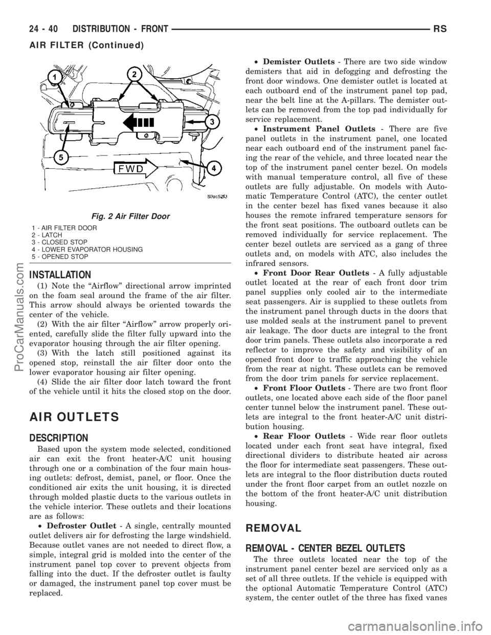
(1) Note the ªAirflowº directional arrow imprinted
on the foam seal around the frame of the air filter.
This arrow should always be oriented towards the
center of the vehicle.
(2) With the air filter ªAirflowº arrow properly ori-
ented, carefully slide the filter fully upward into the
evaporator housing through the air filter opening.
(3) With the latch still positioned against its
opened stop, reinstall the air filter door onto the
lower evaporator housing air filter opening.
(4) Slide the air filter door latch toward the front
of the vehicle until it hits the closed stop on the door.
AIR OUTLETS
DESCRIPTION
Based upon the system mode selected, conditioned
air can exit the front heater-A/C unit housing
through one or a combination of the four main hous-
ing outlets: defrost, demist, panel, or floor. Once the
conditioned air exits the unit housing, it is directed
through molded plastic ducts to the various outlets in
the vehicle interior. These outlets and their locations
are as follows:
²Defroster Outlet- A single, centrally mounted
outlet delivers air for defrosting the large windshield.
Because outlet vanes are not needed to direct flow, a
simple, integral grid is molded into the center of the
instrument panel top cover to prevent objects from
falling into the duct. If the defroster outlet is faulty
or damaged, the instrument panel top cover must be
replaced.²Demister Outlets- There are two side window
demisters that aid in defogging and defrosting the
front door windows. One demister outlet is located at
each outboard end of the instrument panel top pad,
near the belt line at the A-pillars. The demister out-
lets can be removed from the top pad individually for
service replacement.
²Instrument Panel Outlets- There are five
panel outlets in the instrument panel, one located
near each outboard end of the instrument panel fac-
ing the rear of the vehicle, and three located near the
top of the instrument panel center bezel. On models
with manual temperature control, all five of these
outlets are fully adjustable. On models with Auto-
matic Temperature Control (ATC), the center outlet
in the center bezel has fixed vanes because it also
houses the remote infrared temperature sensors for
the front seat positions. The outboard outlets can be
removed individually for service replacement. The
center bezel outlets are serviced as a gang of three
outlets and, on models with ATC, also includes the
infrared sensors.
²Front Door Rear Outlets- A fully adjustable
outlet located at the rear of each front door trim
panel supplies only cooled air to the intermediate
seat passengers. Air is supplied to these outlets from
the instrument panel through ducts in the doors that
use molded seals at the instrument panel to prevent
air leakage. The door ducts are integral to the front
door trim panels. These outlets also incorporate a red
reflector to improve the safety and visibility of an
opened front door to traffic approaching the vehicle
from the rear at night. These outlets can be removed
from the door trim panels for service replacement.
²Front Floor Outlets- There are two front floor
outlets, one located above each side of the floor panel
center tunnel below the instrument panel. These out-
lets are integral to the front heater-A/C unit distri-
bution housing.
²Rear Floor Outlets- Wide rear floor outlets
located under each front seat have integral, fixed
directional dividers to distribute heated air across
the floor for intermediate seat passengers. These out-
lets are integral to the floor distribution ducts routed
under the front floor carpet from an outlet nozzle on
the bottom of the front heater-A/C unit distribution
housing.
REMOVAL
REMOVAL - CENTER BEZEL OUTLETS
The three outlets located near the top of the
instrument panel center bezel are serviced only as a
set of all three outlets. If the vehicle is equipped with
the optional Automatic Temperature Control (ATC)
system, the center outlet of the three has fixed vanes
Fig. 2 Air Filter Door
1 - AIR FILTER DOOR
2-LATCH
3 - CLOSED STOP
4 - LOWER EVAPORATOR HOUSING
5 - OPENED STOP
24 - 40 DISTRIBUTION - FRONTRS
AIR FILTER (Continued)
ProCarManuals.com
Page 2070 of 2177
NOTE: Liquid CO2is required to test the expansion
valve. This material is available from most welding
supply facilities. Liquid CO
2is also available from
companies which service and sell fire extinguish-
ers.
When testing the expansion valve, the work area
and the vehicle temperature must be 21É to 27É C
(70É to 85É F). To test the expansion valve:
(1) Connect a charging station or manifold gauge
set to the refrigerant system service ports. Verify the
refrigerant charge level.
(2) Close all doors, windows and vents to the pas-
senger compartment.
(3) Set the heater-air conditioner controls so that
the compressor is operating, the temperature control
is in the highest temperature position, the mode door
is directing the output to the floor outlets, and the
blower is operating at the highest speed setting.
(4) Start the engine and allow it to idle at 1000
rpm. After the engine has reached normal operating
temperature, allow the passenger compartment to
heat up. This will create the need for maximum
refrigerant flow into the evaporator.
(5) If the refrigerant charge is sufficient, the dis-
charge (high pressure) gauge should read 965 to 1655
kPa (140 to 240 psi). The suction (low pressure)
gauge should read 140 kPa to 207 kPa (20 psi to 30
psi). If OK, go to Step 6. If not OK, replace the faulty
expansion valve.
WARNING:
PROTECT THE SKIN AND EYES FROM EXPOSURE
TO LIQUID CO
2. PERSONAL INJURY CAN RESULT.
(6) If the suction (low pressure) gauge reads
within the specified range, freeze the expansion valve
control head for 30 seconds using liquid CO
2or
another suitable super-cold material.Do not spray
R-134a or R-12 refrigerant on the expansion
valve control head for this test.The suction (low
pressure) gauge reading should drop by 10 psi. If OK,
go to Step 7 If not OK, replace the faulty expansion
valve.
(7) Allow the expansion valve control head to thaw.
The suction (low pressure) gauge reading should sta-
bilize at 140 kPa to 240 kPa (20 psi to 30 psi). If not
OK, replace the faulty expansion valve.
(8) When expansion valve testing is complete, test
the overall air conditioner performance. (Refer to 24 -
HEATING & AIR CONDITIONING - DIAGNOSIS
AND TESTING - A/C PERFORMANCE TEST).
Remove all test equipment before returning the vehi-
cle to service.
REMOVAL
WARNING: REFER TO THE APPLICABLE WARN-
INGS AND CAUTIONS FOR THIS SYSTEM BEFORE
PERFORMING THE FOLLOWING OPERATION.
(Refer to 24 - HEATING & AIR CONDITIONING/
PLUMBING - FRONT - WARNING - A/C PLUMBING)
and (Refer to 24 - HEATING & AIR CONDITIONING/
PLUMBING - FRONT - CAUTION - A/C PLUMBING).
(1) Recover the refrigerant from the refrigerant
system. (Refer to 24 - HEATING & AIR CONDI-
TIONING/PLUMBING - FRONT/REFRIGERANT -
STANDARD PROCEDURE - REFRIGERANT
RECOVERY).
(2) Disconnect and isolate the battery negative
cable.
(3) Remove the air cleaner housing from the right
side of the engine compartment.
(4) Disconnect the drain tube from the wiper mod-
ule drain on the right side of the engine compart-
ment.
(5) Disconnect the headlamp and dash wire har-
ness connector for the A/C pressure transducer from
the transducer on the front liquid line rear section
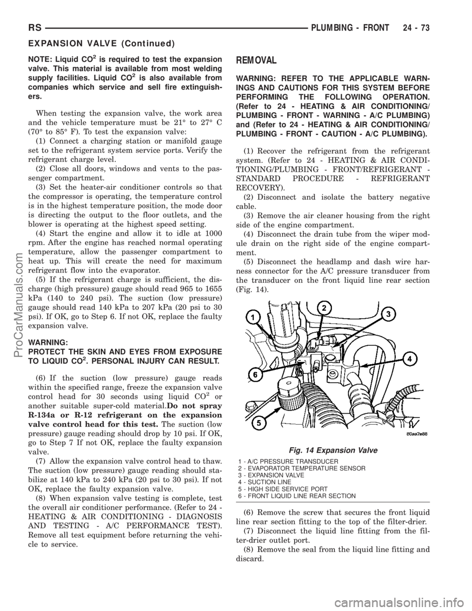
(Fig. 14).
(6) Remove the screw that secures the front liquid
line rear section fitting to the top of the filter-drier.
(7) Disconnect the liquid line fitting from the fil-
ter-drier outlet port.
(8) Remove the seal from the liquid line fitting and
discard.
Fig. 14 Expansion Valve
1 - A/C PRESSURE TRANSDUCER
2 - EVAPORATOR TEMPERATURE SENSOR
3 - EXPANSION VALVE
4 - SUCTION LINE
5 - HIGH SIDE SERVICE PORT
6 - FRONT LIQUID LINE REAR SECTION
RSPLUMBING - FRONT24-73
EXPANSION VALVE (Continued)
ProCarManuals.com
Page 2083 of 2177
K thermocouple. If a digital multimeter is not avail-
able, this tool is also available through the PSE pro-
gram.
NOTE: When connecting the service equipment
couplings to the refrigerant system service ports,
be certain that the valve of each coupling is fully
closed. This will reduce the amount of effort
required to make the connection.
(1) Remove the caps from the refrigerant system
service ports and attach a manifold gauge set or a
R-134a refrigerant recovery/recycling/charging sta-
tion that meets SAE Standard J2210 to the refriger-
ant system.
(2) Attach a clamp-on thermocouple to the liquid
line. The thermocouple must be placed as close to the
A/C pressure transducer as possible to accurately
observe liquid line temperature.
(3) Bring the refrigerant system up to operating
temperature and pressure. This is done by allowing
the engine to run at idle under the following condi-
tions for five minutes.
(a) Front windows are open.
(b) Transaxle in Park.
(c) Front heater-A/C controls set to outside air,
full cool, panel mode, blower high, and compressor
engaged.
(d) If the vehicle is so equipped, the rear heater-
A/C controls must be set to full cool and blower
high.
(4) Raise the liquid line (discharge) pressure to
about 1793 kPa (260 psi) by placing a piece of card-
board over part of the front side of the condenser. To
place the cardboard properly, remove the upper radi-
ator sight shield from the front fascia. Cover only
enough of the condenser to raise and maintain the
liquid line pressure at the specified level.
(5) Observe the liquid line (discharge) pressure
and liquid line temperature. Using the Charge Deter-
mination Chart (Fig. 31), determine whether the
refrigerant system is operating within the Proper
Charge Range.
(a) If the refrigerant system is operating in the
Undercharged area of the chart, add 0.057 kilo-
gram (0.125 pound or 2 ounces) of refrigerant to
the system.
(b) If the refrigerant system is operating in the
Overcharged area of the chart, reclaim 0.057 kilo-
gram (0.125 pound or 2 ounces) of refrigerant from
the system.
(6) Recheck the system charge level following each
refrigerant adjustment. Continue this process until
the system readings are in the Proper Charge Range
area on the Charge Determination Chart.DIAGNOSIS AND TESTING - REFRIGERANT
SYSTEM LEAKS
WARNING: REFER TO THE APPLICABLE WARN-
INGS AND CAUTIONS FOR THIS SYSTEM BEFORE
PERFORMING THE FOLLOWING OPERATION.
(Refer to 24 - HEATING & AIR CONDITIONING/
PLUMBING - FRONT - WARNING - A/C PLUMBING)
and (Refer to 24 - HEATING & AIR CONDITIONING/
PLUMBING - FRONT - CAUTION - A/C PLUMBING).
If the air conditioning system is not cooling prop-
erly, determine if the refrigerant system is fully-
charged. (Refer to 24 - HEATING & AIR
CONDITIONING/PLUMBING - FRONT/REFRIGER-
ANT - DIAGNOSIS AND TESTING - REFRIGER-
ANT SYSTEM CHARGE LEVEL).
If the refrigerant system is low or empty; a leak at
a refrigerant line, connector fitting, component, or
component seal is likely. While an oily residue on or
near refrigerant system lines, connector fittings, com-
ponents, or component seals can indicate the general
location of a possible refrigerant leak, the exact leak
location should be confirmed with an electronic leak
detector prior to component repair or replacement.
An electronic leak detector designed for R-134a
refrigerant is recommended for locating and confirm-
ing refrigerant system leaks. See the operating
instructions supplied by the equipment manufacturer
for proper care and use of this equipment.
To detect a leak in the refrigerant system, perform
one of the following procedures as indicated by the
results of the refrigerant system charge level test.
SYSTEM EMPTY
(1) Evacuate the refrigerant system. (Refer to 24 -
HEATING & AIR CONDITIONING/PLUMBING -
FRONT/REFRIGERANT - STANDARD PROCE-
DURE - REFRIGERANT SYSTEM EVACUATE).
(2) Connect and dispense 0.283 kilograms (0.625
pounds or 10 ounces) of R-134a refrigerant into the
evacuated refrigerant system. (Refer to 24 - HEAT-
ING & AIR CONDITIONING/PLUMBING - FRONT/
REFRIGERANT - STANDARD PROCEDURE -
REFRIGERANT SYSTEM CHARGE).
(3) Proceed to the SYSTEM LOW procedures.
SYSTEM LOW
(1) Position the vehicle in a wind-free work area.
This will aid in detecting small leaks.
(2) Bring the refrigerant system up to operating
temperature and pressure. This is done by allowing
the engine to run at idle under the following condi-
tions for five minutes, then turning the engine off.
(a) Front windows are open.
(b) Rear air conditioner Off (if equipped).
24 - 86 PLUMBING - FRONTRS
REFRIGERANT (Continued)
ProCarManuals.com
Page 2086 of 2177
(4) Open both the suction and discharge valves,
then open the charge valve to allow the heated
refrigerant to flow into the system.
(5) When the transfer of refrigerant has stopped,
close both the suction and discharge valves.
(6) If all of the refrigerant charge did not transfer
from the dispensing device, open all of the windows
in the vehicle and set the heater-air conditioner con-
trols so that the compressor is engaged and the
blower motor is operating at its lowest speed setting.
Run the engine at a steady high idle (about 1400
rpm). If the compressor will not engage, test the com-
pressor clutch control circuit and repair as required.
(7) Open the suction valve to allow the remaining
refrigerant to transfer to the refrigerant system.
WARNING: TAKE CARE NOT TO OPEN THE DIS-
CHARGE (HIGH PRESSURE) VALVE AT THIS TIME.
(8) Close the suction valve and test the system
performance. (Refer to 24 - HEATING & AIR CON-
DITIONING - STANDARD PROCEDURE - A/C PER-
FORMANCE TEST).
(9) Disconnect the charging station and manifold
gauge set from the refrigerant system service ports.
(10) Reinstall the caps onto the refrigerant system
service ports.
(11) Run the HVAC Control Cooldown test to ver-
ify proper operation(Refer to 24 - HEATING & AIR
CONDITIONING - DIAGNOSIS AND TESTING).
STANDARD PROCEDURE - REFRIGERANT
SYSTEM EVACUATE
WARNING: REFER TO THE APPLICABLE WARN-
INGS AND CAUTIONS FOR THIS SYSTEM BEFORE
PERFORMING THE FOLLOWING OPERATION.
(Refer to 24 - HEATING & AIR CONDITIONING/
PLUMBING - FRONT - WARNING - A/C PLUMBING)
and (Refer to 24 - HEATING & AIR CONDITIONING/
PLUMBING - FRONT - CAUTION - A/C PLUMBING).
If the refrigerant system has been open to the
atmosphere, it must be evacuated before the system
can be charged. If moisture and air enters the system
and becomes mixed with the refrigerant, the com-
pressor head pressure will rise above acceptable
operating levels. This will reduce the performance of
the air conditioner and damage the compressor.
Evacuating the refrigerant system will remove the
air and boil the moisture out of the system at near
room temperature. A R-134a refrigerant recovery/re-
cycling/charging station that meets SAE Standard
J2210 must be used to evacuate the refrigerant sys-
tem. See the operating instructions supplied by the
equipment manufacturer for proper care and use ofthis equipment. To evacuate the refrigerant system,
use the following procedure:
NOTE: When connecting the service equipment
couplings to the refrigerant system service ports,
be certain that the valve of each coupling is fully
closed. This will reduce the amount of effort
required to make the connection.
(1) Remove the caps from the refrigerant system
service ports and attach a manifold gauge set and a
R-134a refrigerant recovery/recycling/charging sta-
tion that meets SAE Standard J2210 to the refriger-
ant system.
(2) Open both the suction and discharge valves
and start the charging station vacuum pump.
(3) When the suction gauge has read 88 kPa (26
in. Hg.) vacuum or greater for 45 minutes, close both
the suction and discharge valves and turn off the
vacuum pump. If the refrigerant system fails to
reach the specified vacuum, the system has a leak
that must be corrected. (Refer to 24 - HEATING &
AIR CONDITIONING/PLUMBING - FRONT/RE-
FRIGERANT - STANDARD PROCEDURE -
REFRIGERANT SYSTEM LEAKS).
(4) If the refrigerant system maintains the speci-
fied vacuum for thirty minutes, restart the vacuum
pump, open both the suction and discharge valves,
and evacuate the system for an additional ten min-
utes.
(5) Close both the suction and discharge valves,
and turn off the charging station vacuum pump.
(6) The refrigerant system is now ready to be
charged with R-134a refrigerant. (Refer to 24 -
HEATING & AIR CONDITIONING/PLUMBING -
FRONT/REFRIGERANT - STANDARD PROCE-
DURE - REFRIGERANT SYSTEM CHARGE).
STANDARD PROCEDURE - REFRIGERANT
RECOVERY
WARNING: REFER TO THE APPLICABLE WARN-
INGS AND CAUTIONS FOR THIS SYSTEM BEFORE
PERFORMING THE FOLLOWING OPERATION.
(Refer to 24 - HEATING & AIR CONDITIONING/
PLUMBING - FRONT - WARNING - A/C PLUMBING)
and (Refer to 24 - HEATING & AIR CONDITIONING/
PLUMBING - FRONT - CAUTION - A/C PLUMBING).
A R-134a refrigerant recovery/recycling/charging
station that meets SAE Standard J2210 must be
used to recover the refrigerant from an R-134a refrig-
erant system, whenever the refrigerant system must
be opened for service. See the operating instructions
supplied by the equipment manufacturer for the
proper care and use of this equipment.
RSPLUMBING - FRONT24-89
REFRIGERANT (Continued)
ProCarManuals.com
Page 2094 of 2177
OPERATION
A mechanical sensor in the expansion valve control
head monitors the temperature and pressure of the
refrigerant leaving the evaporator coil through the
suction line, and adjusts the orifice size at the liquid
line to let the proper amount of refrigerant into the
evaporator coil to meet the vehicle cooling require-
ments. Controlling the refrigerant flow through the
evaporator ensures that none of the refrigerant leav-
ing the evaporator is still in a liquid state, which
could damage the compressor.
DIAGNOSIS AND TESTING - EXPANSION VALVE
WARNING: REFER TO THE APPLICABLE WARN-
INGS AND CAUTIONS FOR THIS SYSTEM BEFORE
PERFORMING THE FOLLOWING OPERATION.
(Refer to 24 - HEATING & AIR CONDITIONING/
PLUMBING - FRONT - WARNING - A/C PLUMBING)
and (Refer to 24 - HEATING & AIR CONDITIONING/
PLUMBING - FRONT - CAUTION - A/C PLUMBING).
NOTE: The expansion valve should only be tested
following testing of the compressor.
NOTE: Liquid CO
2is required to test the expansion
valve. This material is available from most welding
supply facilities. Liquid CO
2is also available from
companies which service and sell fire extinguish-
ers.
When testing the expansion valve, the work area
and the vehicle temperature must be 21É to 27É C
(70É to 85É F). To test the expansion valve:
(1) Connect a charging station or manifold gauge
set to the refrigerant system service ports. Verify the
refrigerant charge level.
(2) Close all doors, windows and vents to the pas-
senger compartment.
(3) Set the heater-air conditioner controls so that
the compressor is operating, the temperature control
is in the highest temperature position, the mode door
is directing the output to the floor outlets, and the
blower is operating at the highest speed setting.
(4) Start the engine and allow it to idle at 1000
rpm. After the engine has reached normal operating
temperature, allow the passenger compartment to
heat up. This will create the need for maximum
refrigerant flow into the evaporator.
(5) If the refrigerant charge is sufficient, the dis-
charge (high pressure) gauge should read 965 to 1655
kPa (140 to 240 psi). The suction (low pressure)
gauge should read 140 kPa to 207 kPa (20 psi to 30
psi). If OK, go to Step 6. If not OK, replace the faulty
expansion valve.WARNING: PROTECT THE SKIN AND EYES FROM
EXPOSURE TO LIQUID CO
2. PERSONAL INJURY
CAN RESULT.
(6) If the suction (low pressure) gauge reads
within the specified range, freeze the expansion valve
control head for 30 seconds using liquid CO
2or
another suitable super-cold material.Do not spray
R-134a or R-12 refrigerant on the expansion
valve control head for this test.The suction (low
pressure) gauge reading should drop by 10 psi. If OK,
go to Step 7 If not OK, replace the faulty expansion
valve.
(7) Allow the expansion valve control head to thaw.
The suction (low pressure) gauge reading should sta-
bilize at 140 kPa to 240 kPa (20 psi to 30 psi). If not
OK, replace the faulty expansion valve.
(8) When expansion valve testing is complete, test
the overall air conditioner performance. (Refer to 24 -
HEATING & AIR CONDITIONING - DIAGNOSIS
AND TESTING - A/C PERFORMANCE TEST).
Remove all test equipment before returning the vehi-
cle to service.
REMOVAL
WARNING: REFER TO THE APPLICABLE WARN-
INGS AND CAUTIONS FOR THIS SYSTEM BEFORE
PERFORMING THE FOLLOWING OPERATION.
(Refer to 24 - HEATING & AIR CONDITIONING/
PLUMBING - FRONT - WARNING - A/C PLUMBING),
(Refer to 24 - HEATING & AIR CONDITIONING/
PLUMBING - FRONT - CAUTION - A/C PLUMBING),
and (Refer to 24 - HEATING & AIR CONDITIONING/
PLUMBING - FRONT - WARNING - HEATER PLUMB-
ING).
(1) Remove the rear heater-A/C unit housing from
the vehicle. (Refer to 24 - HEATING & AIR CONDI-
TIONING/DISTRIBUTION - REAR/REAR HEATER-
A/C HOUSING - REMOVAL).
(2) Carefully remove the foam insulator wrap from
the rear expansion valve.
(3) Remove the rear evaporator line extension from
the expansion valve. (Refer to 24 - HEATING & AIR
CONDITIONING/PLUMBING - REAR/EVAPORA-
TOR - REMOVAL - EVAPORATOR LINE EXTEN-
SION).
(4) Remove the two screws that secure the expan-
sion valve to the evaporator tube sealing plate.
(5) Remove the expansion valve from the evapora-
tor tubes.
(6) Remove the seals from the evaporator tube fit-
tings and discard.
(7) Install plugs in, or tape over the opened evap-
orator tube fittings and both expansion valve ports.
RSPLUMBING - REAR24-97
EXPANSION VALVE (Continued)
ProCarManuals.com