2003 CHRYSLER VOYAGER Windows
[x] Cancel search: WindowsPage 1010 of 2177
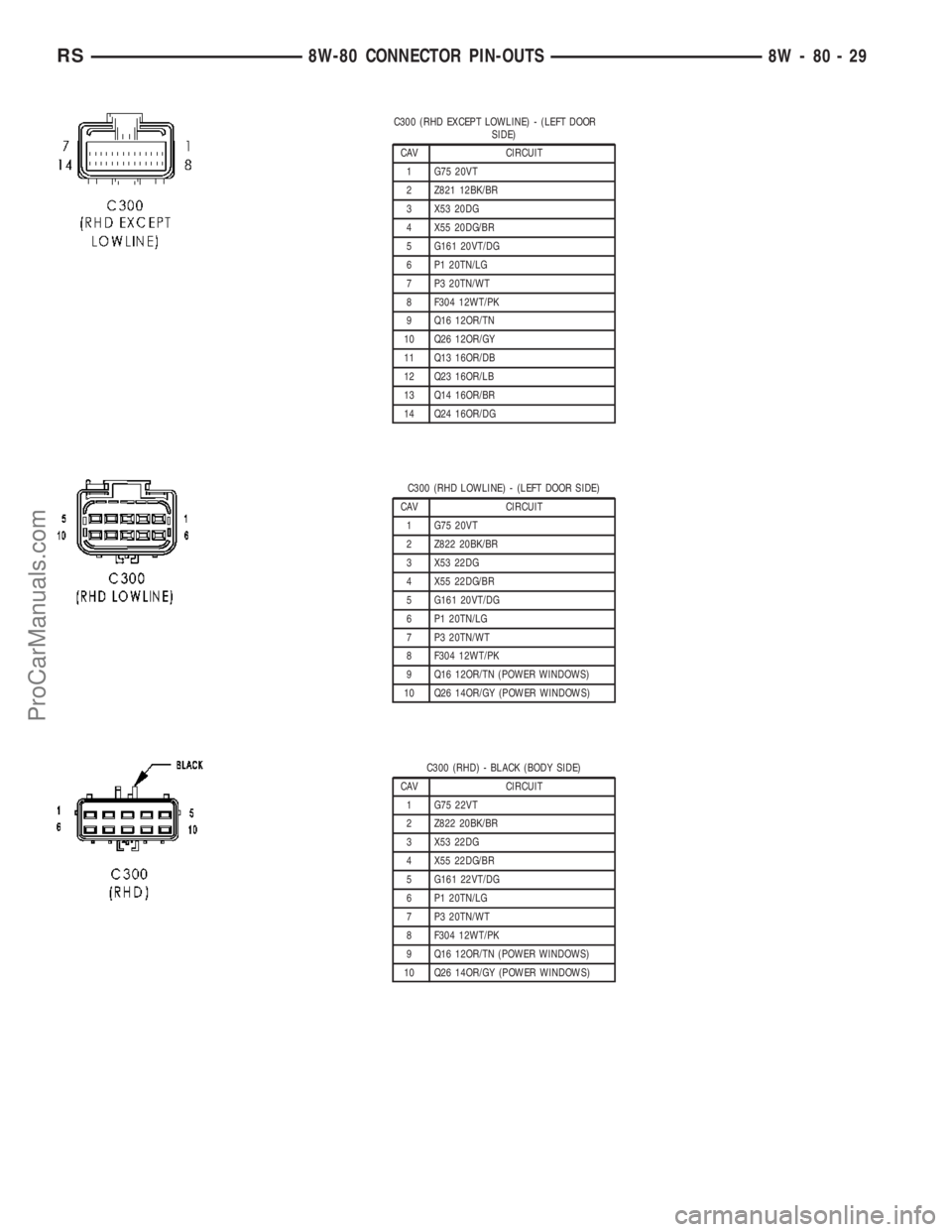
C300 (RHD EXCEPT LOWLINE) - (LEFT DOOR
SIDE)
CAV CIRCUIT
1 G75 20VT
2 Z821 12BK/BR
3 X53 20DG
4 X55 20DG/BR
5 G161 20VT/DG
6 P1 20TN/LG
7 P3 20TN/WT
8 F304 12WT/PK
9 Q16 12OR/TN
10 Q26 12OR/GY
11 Q13 16OR/DB
12 Q23 16OR/LB
13 Q14 16OR/BR
14 Q24 16OR/DG
C300 (RHD LOWLINE) - (LEFT DOOR SIDE)
CAV CIRCUIT
1 G75 20VT
2 Z822 20BK/BR
3 X53 22DG
4 X55 22DG/BR
5 G161 20VT/DG
6 P1 20TN/LG
7 P3 20TN/WT
8 F304 12WT/PK
9 Q16 12OR/TN (POWER WINDOWS)
10 Q26 14OR/GY (POWER WINDOWS)
C300 (RHD) - BLACK (BODY SIDE)
CAV CIRCUIT
1 G75 22VT
2 Z822 20BK/BR
3 X53 22DG
4 X55 22DG/BR
5 G161 22VT/DG
6 P1 20TN/LG
7 P3 20TN/WT
8 F304 12WT/PK
9 Q16 12OR/TN (POWER WINDOWS)
10 Q26 14OR/GY (POWER WINDOWS)
RS8W-80 CONNECTOR PIN-OUTS8W-80-29
ProCarManuals.com
Page 1013 of 2177
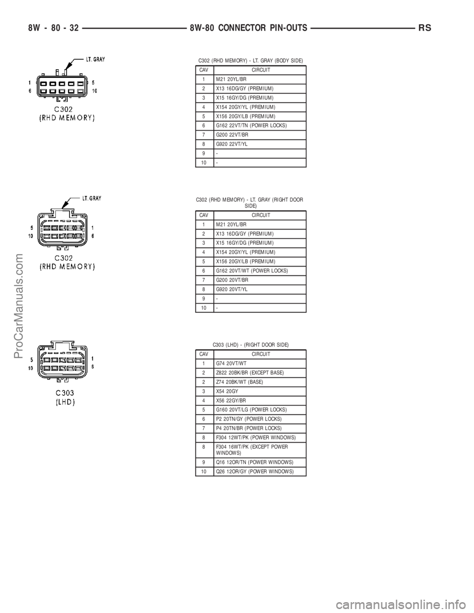
C302 (RHD MEMORY) - LT. GRAY (BODY SIDE)
CAV CIRCUIT
1 M21 20YL/BR
2 X13 16DG/GY (PREMIUM)
3 X15 16GY/DG (PREMIUM)
4 X154 20GY/YL (PREMIUM)
5 X156 20GY/LB (PREMIUM)
6 G162 22VT/TN (POWER LOCKS)
7 G200 22VT/BR
8 G920 22VT/YL
9-
10 -
C302 (RHD MEMORY) - LT. GRAY (RIGHT DOOR
SIDE)
CAV CIRCUIT
1 M21 20YL/BR
2 X13 16DG/GY (PREMIUM)
3 X15 16GY/DG (PREMIUM)
4 X154 20GY/YL (PREMIUM)
5 X156 20GY/LB (PREMIUM)
6 G162 20VT/WT (POWER LOCKS)
7 G200 20VT/BR
8 G920 20VT/YL
9-
10 -
C303 (LHD) - (RIGHT DOOR SIDE)
CAV CIRCUIT
1 G74 20VT/WT
2 Z822 20BK/BR (EXCEPT BASE)
2 Z74 20BK/WT (BASE)
3 X54 20GY
4 X56 22GY/BR
5 G160 20VT/LG (POWER LOCKS)
6 P2 20TN/GY (POWER LOCKS)
7 P4 20TN/BR (POWER LOCKS)
8 F304 12WT/PK (POWER WINDOWS)
8 F304 16WT/PK (EXCEPT POWER
WINDOWS)
9 Q16 12OR/TN (POWER WINDOWS)
10 Q26 12OR/GY (POWER WINDOWS)
8W - 80 - 32 8W-80 CONNECTOR PIN-OUTSRS
ProCarManuals.com
Page 1014 of 2177
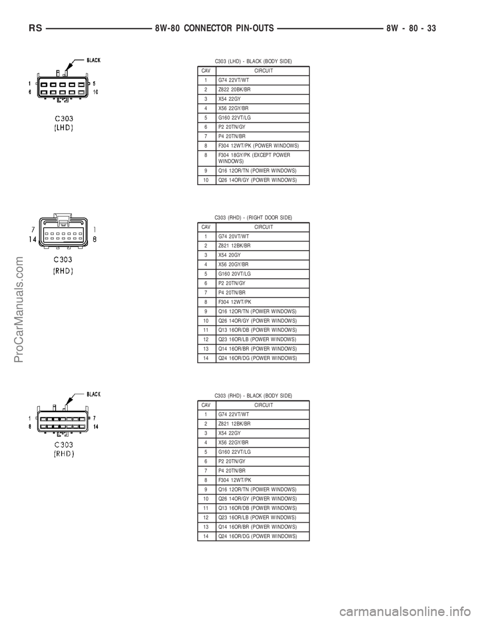
C303 (LHD) - BLACK (BODY SIDE)
CAV CIRCUIT
1 G74 22VT/WT
2 Z822 20BK/BR
3 X54 22GY
4 X56 22GY/BR
5 G160 22VT/LG
6 P2 20TN/GY
7 P4 20TN/BR
8 F304 12WT/PK (POWER WINDOWS)
8 F304 18GY/PK (EXCEPT POWER
WINDOWS)
9 Q16 12OR/TN (POWER WINDOWS)
10 Q26 14OR/GY (POWER WINDOWS)
C303 (RHD) - (RIGHT DOOR SIDE)
CAV CIRCUIT
1 G74 20VT/WT
2 Z821 12BK/BR
3 X54 20GY
4 X56 20GY/BR
5 G160 20VT/LG
6 P2 20TN/GY
7 P4 20TN/BR
8 F304 12WT/PK
9 Q16 12OR/TN (POWER WINDOWS)
10 Q26 14OR/GY (POWER WINDOWS)
11 Q13 16OR/DB (POWER WINDOWS)
12 Q23 16OR/LB (POWER WINDOWS)
13 Q14 16OR/BR (POWER WINDOWS)
14 Q24 16OR/DG (POWER WINDOWS)
C303 (RHD) - BLACK (BODY SIDE)
CAV CIRCUIT
1 G74 22VT/WT
2 Z821 12BK/BR
3 X54 22GY
4 X56 22GY/BR
5 G160 22VT/LG
6 P2 20TN/GY
7 P4 20TN/BR
8 F304 12WT/PK
9 Q16 12OR/TN (POWER WINDOWS)
10 Q26 14OR/GY (POWER WINDOWS)
11 Q13 16OR/DB (POWER WINDOWS)
12 Q23 16OR/LB (POWER WINDOWS)
13 Q14 16OR/BR (POWER WINDOWS)
14 Q24 16OR/DG (POWER WINDOWS)
RS8W-80 CONNECTOR PIN-OUTS8W-80-33
ProCarManuals.com
Page 1037 of 2177
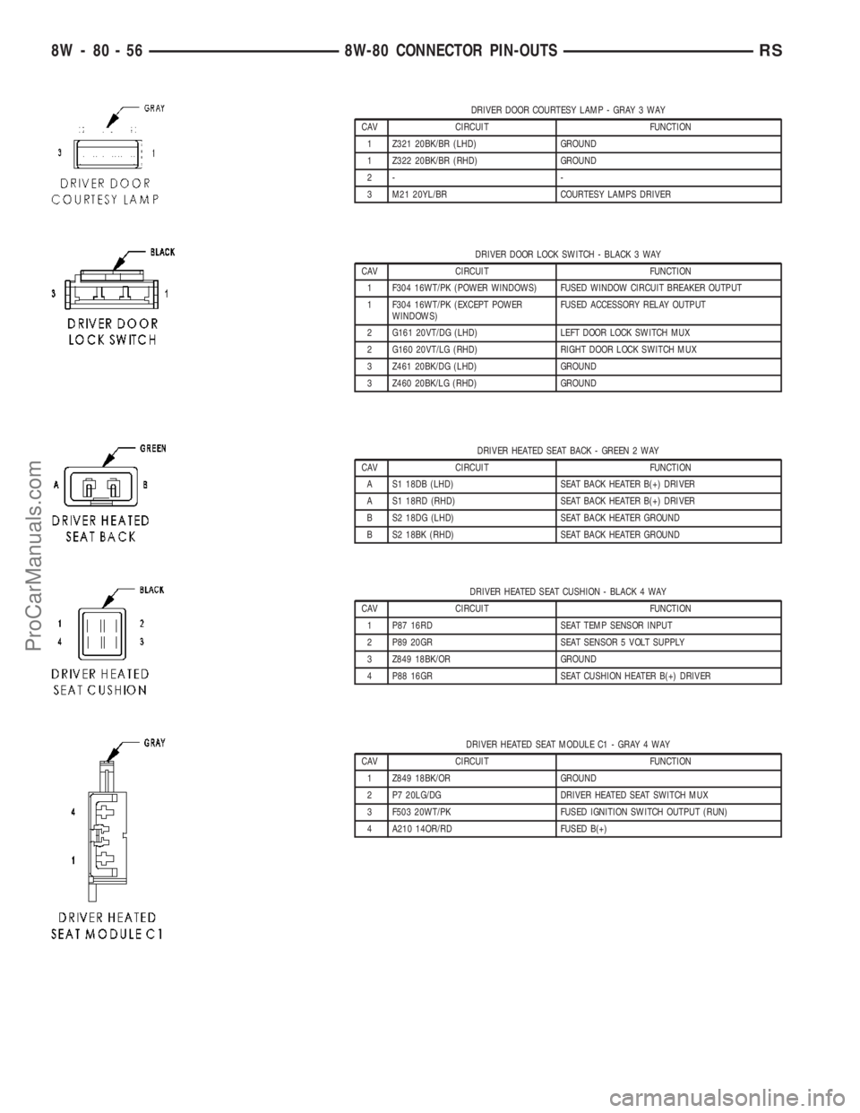
DRIVER DOOR COURTESY LAMP - GRAY 3 WAY
CAV CIRCUIT FUNCTION
1 Z321 20BK/BR (LHD) GROUND
1 Z322 20BK/BR (RHD) GROUND
2- -
3 M21 20YL/BR COURTESY LAMPS DRIVER
DRIVER DOOR LOCK SWITCH - BLACK 3 WAY
CAV CIRCUIT FUNCTION
1 F304 16WT/PK (POWER WINDOWS) FUSED WINDOW CIRCUIT BREAKER OUTPUT
1 F304 16WT/PK (EXCEPT POWER
WINDOWS)FUSED ACCESSORY RELAY OUTPUT
2 G161 20VT/DG (LHD) LEFT DOOR LOCK SWITCH MUX
2 G160 20VT/LG (RHD) RIGHT DOOR LOCK SWITCH MUX
3 Z461 20BK/DG (LHD) GROUND
3 Z460 20BK/LG (RHD) GROUND
DRIVER HEATED SEAT BACK - GREEN 2 WAY
CAV CIRCUIT FUNCTION
A S1 18DB (LHD) SEAT BACK HEATER B(+) DRIVER
A S1 18RD (RHD) SEAT BACK HEATER B(+) DRIVER
B S2 18DG (LHD) SEAT BACK HEATER GROUND
B S2 18BK (RHD) SEAT BACK HEATER GROUND
DRIVER HEATED SEAT CUSHION - BLACK 4 WAY
CAV CIRCUIT FUNCTION
1 P87 16RD SEAT TEMP SENSOR INPUT
2 P89 20GR SEAT SENSOR 5 VOLT SUPPLY
3 Z849 18BK/OR GROUND
4 P88 16GR SEAT CUSHION HEATER B(+) DRIVER
DRIVER HEATED SEAT MODULE C1 - GRAY 4 WAY
CAV CIRCUIT FUNCTION
1 Z849 18BK/OR GROUND
2 P7 20LG/DG DRIVER HEATED SEAT SWITCH MUX
3 F503 20WT/PK FUSED IGNITION SWITCH OUTPUT (RUN)
4 A210 14OR/RD FUSED B(+)
8W - 80 - 56 8W-80 CONNECTOR PIN-OUTSRS
ProCarManuals.com
Page 1060 of 2177
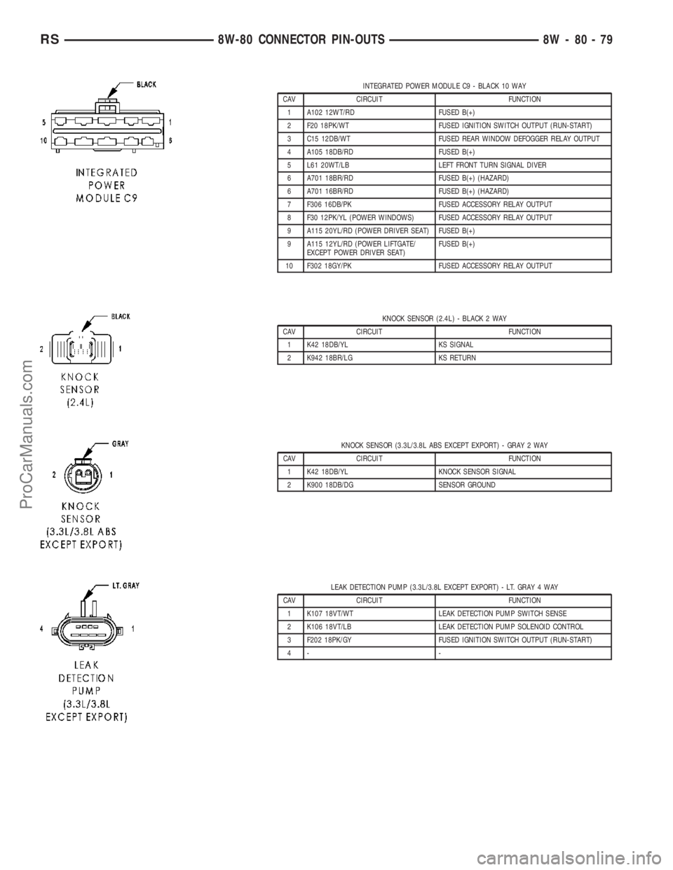
INTEGRATED POWER MODULE C9 - BLACK 10 WAY
CAV CIRCUIT FUNCTION
1 A102 12WT/RD FUSED B(+)
2 F20 18PK/WT FUSED IGNITION SWITCH OUTPUT (RUN-START)
3 C15 12DB/WT FUSED REAR WINDOW DEFOGGER RELAY OUTPUT
4 A105 18DB/RD FUSED B(+)
5 L61 20WT/LB LEFT FRONT TURN SIGNAL DIVER
6 A701 18BR/RD FUSED B(+) (HAZARD)
6 A701 16BR/RD FUSED B(+) (HAZARD)
7 F306 16DB/PK FUSED ACCESSORY RELAY OUTPUT
8 F30 12PK/YL (POWER WINDOWS) FUSED ACCESSORY RELAY OUTPUT
9 A115 20YL/RD (POWER DRIVER SEAT) FUSED B(+)
9 A115 12YL/RD (POWER LIFTGATE/
EXCEPT POWER DRIVER SEAT)FUSED B(+)
10 F302 18GY/PK FUSED ACCESSORY RELAY OUTPUT
KNOCK SENSOR (2.4L) - BLACK 2 WAY
CAV CIRCUIT FUNCTION
1 K42 18DB/YL KS SIGNAL
2 K942 18BR/LG KS RETURN
KNOCK SENSOR (3.3L/3.8L ABS EXCEPT EXPORT) - GRAY 2 WAY
CAV CIRCUIT FUNCTION
1 K42 18DB/YL KNOCK SENSOR SIGNAL
2 K900 18DB/DG SENSOR GROUND
LEAK DETECTION PUMP (3.3L/3.8L EXCEPT EXPORT) - LT. GRAY 4 WAY
CAV CIRCUIT FUNCTION
1 K107 18VT/WT LEAK DETECTION PUMP SWITCH SENSE
2 K106 18VT/LB LEAK DETECTION PUMP SOLENOID CONTROL
3 F202 18PK/GY FUSED IGNITION SWITCH OUTPUT (RUN-START)
4- -
RS8W-80 CONNECTOR PIN-OUTS8W-80-79
ProCarManuals.com
Page 1079 of 2177
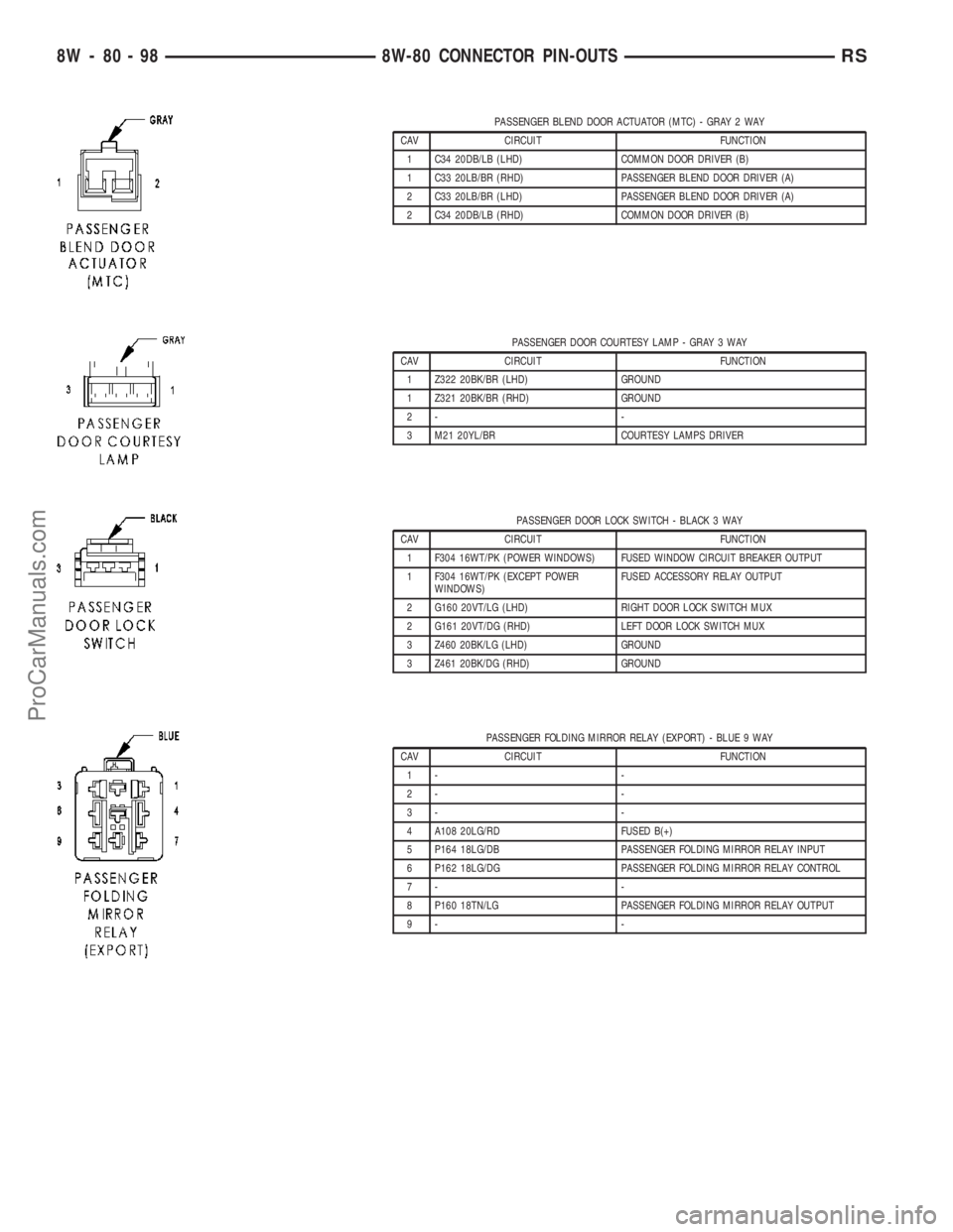
PASSENGER BLEND DOOR ACTUATOR (MTC) - GRAY 2 WAY
CAV CIRCUIT FUNCTION
1 C34 20DB/LB (LHD) COMMON DOOR DRIVER (B)
1 C33 20LB/BR (RHD) PASSENGER BLEND DOOR DRIVER (A)
2 C33 20LB/BR (LHD) PASSENGER BLEND DOOR DRIVER (A)
2 C34 20DB/LB (RHD) COMMON DOOR DRIVER (B)
PASSENGER DOOR COURTESY LAMP - GRAY 3 WAY
CAV CIRCUIT FUNCTION
1 Z322 20BK/BR (LHD) GROUND
1 Z321 20BK/BR (RHD) GROUND
2- -
3 M21 20YL/BR COURTESY LAMPS DRIVER
PASSENGER DOOR LOCK SWITCH - BLACK 3 WAY
CAV CIRCUIT FUNCTION
1 F304 16WT/PK (POWER WINDOWS) FUSED WINDOW CIRCUIT BREAKER OUTPUT
1 F304 16WT/PK (EXCEPT POWER
WINDOWS)FUSED ACCESSORY RELAY OUTPUT
2 G160 20VT/LG (LHD) RIGHT DOOR LOCK SWITCH MUX
2 G161 20VT/DG (RHD) LEFT DOOR LOCK SWITCH MUX
3 Z460 20BK/LG (LHD) GROUND
3 Z461 20BK/DG (RHD) GROUND
PASSENGER FOLDING MIRROR RELAY (EXPORT) - BLUE 9 WAY
CAV CIRCUIT FUNCTION
1- -
2- -
3- -
4 A108 20LG/RD FUSED B(+)
5 P164 18LG/DB PASSENGER FOLDING MIRROR RELAY INPUT
6 P162 18LG/DG PASSENGER FOLDING MIRROR RELAY CONTROL
7- -
8 P160 18TN/LG PASSENGER FOLDING MIRROR RELAY OUTPUT
9- -
8W - 80 - 98 8W-80 CONNECTOR PIN-OUTSRS
ProCarManuals.com
Page 1175 of 2177

SPECIAL TOOLS
POWER DISTRIBUTION SYSTEMS
ACCESSORY RELAY
DESCRIPTION
The accessory relay is an electromechanical device
that switches fused battery current to the accessory
powered vehicle circuits when the ignition switch is
turned to the Accessory or On positions. The delay
feature will maintain power to the accessories for 45
seconds after the ignition is shut off or until a door is
opened. This allows sufficient time to close windows
and park the windshield wipers. The accessory relay
is located in the Integrated Power Module (IPM) in
the engine compartment.
The accessory relay is a International Standards
Organization (ISO) relay. Relays conforming to the
ISO specifications have common physical dimensions,
current capacities, terminal patterns, and terminal
functions.
The accessory relay cannot be repaired or adjusted
and, if faulty or damaged, it must be replaced.
OPERATION
The ISO relay consists of an electromagnetic coil, a
resistor or diode, and three (two fixed and one mov-
able) electrical contacts. The movable (common feed)
relay contact is held against one of the fixed contacts
(normally closed) by spring pressure. When the elec-
tromagnetic coil is energized, it draws the movable
contact away from the normally closed fixed contact,
and holds it against the other (normally open) fixed
contact.
When the electromagnetic coil is de-energized,
spring pressure returns the movable contact to the
normally closed position. The resistor or diode is con-
nected in parallel with the electromagnetic coil in therelay, and helps to dissipate voltage spikes that are
produced when the coil is de-energized.
DIAGNOSIS AND TESTING
DIAGNOSIS & TESTING - ACCESSORY RELAY
The accessory relay (Fig. 1) is located in the Inte-
grated Power Module (IPM), in the engine compart-
ment. For complete circuit diagrams, refer toWiring
Diagrams.
(1) Remove the accessory relay from the IPM.
Refer toAccessory Relayin the Removal and
Installation section of this group for the procedure.
(2) A relay in the de-energized position should
have continuity between terminals 87A and 30, and
no continuity between terminals 87 and 30. If OK, go
to Step 3. If not OK, replace the faulty relay.
(3) Resistance between terminals 85 and 86 (elec-
tromagnet) should be 75 5 ohms. If OK, go to Step
4. If not OK, replace the faulty relay.
(4) Connect a battery to terminals 85 and 86.
There should now be continuity between terminals
30 and 87, and no continuity between terminals 87A
and 30. If OK, perform the Relay Circuit Test that
follows. If not OK, replace the faulty relay.
DIAGNOSIS & TESTING - RELAY CIRCUIT TEST
(1) The relay common feed terminal cavity (30) of
the IPM is connected to battery voltage and should
be hot at all times. Check for battery voltage at the
fused B(+) circuit cavity in the IPM receptacle for the
accessory relay. If OK, go to Step 2. If not OK, repair
the fused B(+) circuit to the IPM fuse as required.
(2) The relay normally closed terminal (87A) is
connected to terminal 30 in the de-energized position,
but is not used for this application. Go to Step 3.
(3) The relay normally open terminal (87) is con-
nected to the common feed terminal (30) in the ener-
gized position. This terminal supplies battery voltage
Terminal Pick Kit 6680
Fig. 1 Accessory Relay
8W - 97 - 2 8W-97 POWER DISTRIBUTION SYSTEMRS
POWER DISTRIBUTION SYSTEM (Continued)
ProCarManuals.com
Page 1373 of 2177
WARNING: RELEASE FUEL SYSTEM PRESSURE
BEFORE DISCONNECTING A QUICK-CONNECT FIT-
TINGS. REFER TO THE FUEL PRESSURE RELEASE
PROCEDURE.
(1) Perform Fuel Pressure Release Procedure.
Refer to the Fuel Pressure Release Procedure in this
section.
(2) Disconnect negative cable from battery or aux-
iliary jumper terminal.
(3) Squeeze retainer tabs together and pull fuel
tube/quick-connect fitting assembly off of fuel tube
nipple. The retainer will remain on fuel tube.
INSTALLATION
CAUTION: Never install a quick-connect fitting with-
out the retainer being either on the fuel tube or
already in the quick-connect fitting. In either case,
ensure the retainer locks securely into the quick-
connect fitting by firmly pulling on fuel tube and fit-
ting to ensure it is secured.
(1) Using a clean lint free cloth, clean the fuel tube
nipple and retainer.
(2) Prior to connecting the fitting to the fuel tube,
coat the fuel tube nipple with clean engine oil.
(3) Push the quick-connect fitting over the fuel
tube until theretainer seats and a click is heard.
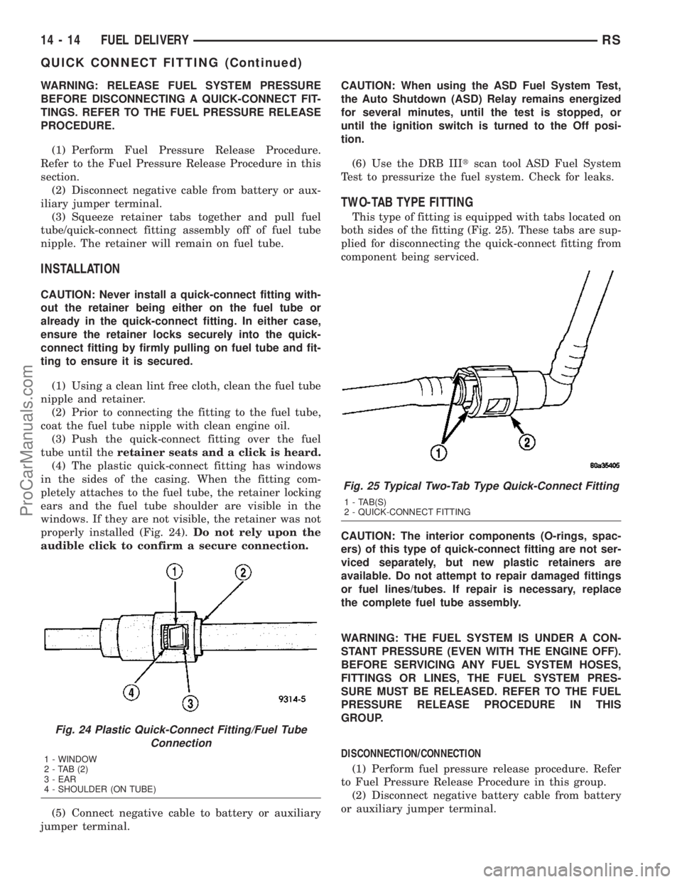
(4) The plastic quick-connect fitting has windows
in the sides of the casing. When the fitting com-
pletely attaches to the fuel tube, the retainer locking
ears and the fuel tube shoulder are visible in the
windows. If they are not visible, the retainer was not
properly installed (Fig. 24).Do not rely upon the
audible click to confirm a secure connection.
(5) Connect negative cable to battery or auxiliary
jumper terminal.CAUTION: When using the ASD Fuel System Test,
the Auto Shutdown (ASD) Relay remains energized
for several minutes, until the test is stopped, or
until the ignition switch is turned to the Off posi-
tion.
(6) Use the DRB IIItscan tool ASD Fuel System
Test to pressurize the fuel system. Check for leaks.
TWO-TAB TYPE FITTING
This type of fitting is equipped with tabs located on
both sides of the fitting (Fig. 25). These tabs are sup-
plied for disconnecting the quick-connect fitting from
component being serviced.
CAUTION: The interior components (O-rings, spac-
ers) of this type of quick-connect fitting are not ser-
viced separately, but new plastic retainers are
available. Do not attempt to repair damaged fittings
or fuel lines/tubes. If repair is necessary, replace
the complete fuel tube assembly.
WARNING: THE FUEL SYSTEM IS UNDER A CON-
STANT PRESSURE (EVEN WITH THE ENGINE OFF).
BEFORE SERVICING ANY FUEL SYSTEM HOSES,
FITTINGS OR LINES, THE FUEL SYSTEM PRES-
SURE MUST BE RELEASED. REFER TO THE FUEL
PRESSURE RELEASE PROCEDURE IN THIS
GROUP.
DISCONNECTION/CONNECTION
(1) Perform fuel pressure release procedure. Refer
to Fuel Pressure Release Procedure in this group.
(2) Disconnect negative battery cable from battery
or auxiliary jumper terminal.
Fig. 24 Plastic Quick-Connect Fitting/Fuel Tube
Connection
1 - WINDOW
2-TAB(2)
3 - EAR
4 - SHOULDER (ON TUBE)
Fig. 25 Typical Two-Tab Type Quick-Connect Fitting
1 - TAB(S)
2 - QUICK-CONNECT FITTING
14 - 14 FUEL DELIVERYRS
QUICK CONNECT FITTING (Continued)
ProCarManuals.com