2003 CHRYSLER VOYAGER crossmember reinforcement
[x] Cancel search: crossmember reinforcementPage 62 of 2177

(3) Check position of the stabilizer bar in the front
suspension cradle. The center of the curved section of
the stabilizer bar must be aligned with the raised
line in the center of the front suspension cradle (Fig.
37).
(4) Install the stabilizer bar link mounting stud
through the hole in each end of the stabilizer bar
(Fig. 33).
CAUTION: When installing the nut on the mounting
stud of the stabilizer bar link, do not allow the stud
to rotate in it's socket. Hold the stud from rotating
by placing an open-end wrench on the flat
machined into the stud (Fig. 33).
(5) Hand-thread the nut on the end of each stabi-
lizer bar link stud. Hold the studs from turning by
placing an open-end wrench on the flat machined
into the link's mounting stud, then tighten each nut
while holding the wrench in place (Fig. 33). Tighten
each nut to a torque of 88 N´m (65 ft. lbs.).
(6) Tighten the stabilizer bar bushing retainer to
cradle attaching bolts (Fig. 34) to 68 N´m (50 ft. lbs.)
torque.
(7) Install the reinforcement on the front suspen-
sion cradle crossmember and install the bolts attach-
ing the reinforcement to the cradle crossmember
(Fig. 32). Tighten the M-14 size bolts to a torque of
153 N´m (113 ft. lbs.). Tighten the M-12 size bolts to
a torque of 106 N´m (78 ft. lbs.).
(8) Install the lower control arm rear bushing
retainer bolts through reinforcement on each side of
each lower control arm rear bushing. Tighten these
M-10 size bolts to a torque of 61 N´m (45 ft. lbs.).(9) Install the two bolts and bushings attaching
the reinforcement and rear of cradle crossmember to
body of vehicle (Fig. 32). Tighten bolts to a torque of
163 N´m (120 ft. lbs.).
(10) Install the power steering cooler (Fig. 31).
Tighten bolts to a torque of 11 N´m (100 in. lbs.).
(11) Lower the vehicle.
STRUT
DESCRIPTION - STRUT ASSEMBLY
A Macpherson type strut assembly is used in place
of a conventional front suspension's upper control
arm and upper ball joint. The bottom of the strut
mounts directly to the steering knuckle using two
bolts and nuts going through the strut clevis bracket
and steering knuckle. The top of the strut mounts
directly to the strut tower of the vehicle using the
threaded studs on the strut assemblies upper mount.
The strut assembly includes the components listed
in the figure (Fig. 38).
Each component is serviced by removing the strut
assembly from the vehicle and disassembling it.
The coil springs are side-oriented. Springs on the
left side of the vehicle have a left-hand wind top-to-
bottom while springs on the right side have a right-
hand wind top-to-bottom. This helps provide better
vehicle stability during jounce and rebound maneu-
vers of the front suspension. Left and right springs
must not be interchanged. Coil springs are rated sep-
arately for each corner or side of the vehicle depend-
ing on optional equipment and type of vehicle
service. If the coil springs require replacement, be
sure that the springs are replaced with springs meet-
ing the correct load rating and spring rate for the
vehicle and its specific options.
OPERATION - STRUT ASSEMBLY
The strut assembly cushions the ride of the vehicle,
controlling vibration, along with jounce and rebound
of the suspension.
The coil spring controls ride quality and maintains
proper ride height.
The spring isolators isolate the coil spring at the
top and bottom from coming into metal-to-metal con-
tact with the upper seat and strut.
The jounce bumper limits suspension travel and
metal-to-metal contact under full jounce condition.
The strut dampens jounce and rebound motions of
the coil spring and suspension.
During steering maneuvers, the strut assembly
(through a pivot bearing in the upper strut mount)
and steering knuckle (through the lower ball joint)
turn as an assembly.
Fig. 37 Stabilizer Bar Correctly Positioned In Cradle
1 - RAISED BEAD
2-SWAYBAR
3 - WHEN INSTALLING SWAY BAR THE RAISED BEAD ON THE
SUSPENSION CRADLE MUST BE IN THE CENTER OF RADIUS
IN SWAY BAR
4 - FRONT SUSPENSION CRADLE
RSFRONT SUSPENSION2-19
STABILIZER BAR (Continued)
ProCarManuals.com
Page 284 of 2177

(3) Position a new gasket over the thermostat and
connector making sure thermostat is in proper posi-
tion and in the recess provided.
(4) Install thermostat and connector assembly to
the intake manifold (Fig. 10). Tighten bolts to 28
N´m (250 in. lbs.).
(5) Install the radiator upper hose to coolant outlet
connector (Fig. 9).
(6) Refill the cooling system to the proper level.
(Refer to 7 - COOLING - STANDARD PROCEDURE)
RADIATOR
REMOVAL
(1) Disconnect negative cable from battery.
(2) Remove radiator upper crossmember support.
(Refer to 23 - BODY/EXTERIOR/GRILLE OPENING
REINFORCEMENT - REMOVAL)
WARNING: DO NOT REMOVE THE CYLINDER
BLOCK PLUG OR THE RADIATOR DRAINCOCK
WITH THE SYSTEM HOT AND UNDER PRESSURE
BECAUSE SERIOUS BURNS FROM COOLANT CAN
OCCUR.
(3) Drain the cooling system. (Refer to 7 - COOL-
ING - STANDARD PROCEDURE)
(4) Remove the radiator fans. (Refer to 7 - COOL-
ING/ENGINE/RADIATOR FAN - REMOVAL)
(5) Disconnect coolant reserve/recovery hose.
(6) Remove vapor purge solenoid from mounting
bracket.
(7) Disconnect upper and lower hoses from the
radiator (Fig. 13) or (Fig. 14).(8) Remove the A/C condenser side brackets to
radiator attaching screws (Fig. 15). Separate the con-
denser from the radiator by lifting upward to disen-
gage from lower mounts (Fig. 15). Allow the
condenser to rest in front of radiator.
(9) Radiator can now be lifted free from engine
compartment.Care should be taken not to dam-
age radiator cooling fins or water tubes during
removal.
INSTALLATION
(1)Be sure the air seal is in position before
radiator is installed.Slide radiator down into posi-
tion. Seat the radiator with the rubber isolators into
the mounting holes provided, with a 10 lbs. force.
(2) Position air conditioning condenser onto the
radiator lower mounts and install upper screws (Fig.
15). Tighten fasteners to 5 N´m (45 in. lbs.).
(3) Install the radiator upper and lower hoses (Fig.
13) or (Fig. 14).
(4) Connect the coolant reserve/recovery hose.
(5) Connect the vapor purge solenoid to the mount-
ing bracket.
(6) Install the radiator fans. (Refer to 7 - COOL-
ING/ENGINE/RADIATOR FAN - INSTALLATION)
(7) Install the radiator upper crossmember sup-
port. (Refer to 23 - BODY/EXTERIOR/GRILLE
OPENING REINFORCEMENT - INSTALLATION)
(8) Fill the cooling system. (Refer to 7 - COOLING
- STANDARD PROCEDURE)
(9) Connect negative cable to battery.
Fig. 13 Radiator Hoses to Radiator - 2.4L
1 - UPPER HOSE
2 - LOWER HOSE
3 - HOSE SUPPORT CLIP
Fig. 14 Radiator Hoses to Radiator - 3.3/3.8L
1 - UPPER HOSE
2 - LOWER HOSE
RSENGINE7-25
ENGINE COOLANT THERMOSTAT - 3.3/3.8L (Continued)
ProCarManuals.com
Page 289 of 2177

REMOVAL
There are no repairs to be made to the fan or
shroud assembly. If the fan is warped, cracked, or
otherwise damaged, it must be replaced as an assem-
bly (Fig. 21).
(1) Remove the radiator upper crossmember. (Refer
to 23 - BODY/EXTERIOR/GRILLE OPENING REIN-
FORCEMENT - REMOVAL)
(2) Disconnect the radiator fan electrical connec-
tors.
(3) Remove radiator fan(s) retaining screw (Fig.
21).
(4) Remove the radiator fan(s) by lifting upward to
release from mounts.
INSTALLATION
(1) Install the radiator fan(s) into mounts and
attaching clips on the radiator.
(2) Install radiator fan(s) attaching screws (Fig.
21). Tighten to 5 N´m (45 in. lbs.).
(3) Connect the radiator fan(s) electrical connec-
tors.
(4) Install the radiator upper support crossmem-
ber. (Refer to 23 - BODY/EXTERIOR/GRILLE OPEN-
ING REINFORCEMENT - INSTALLATION)
(5) Install the upper radiator mounts to the cross-
member bolts, if removed. Tighten to 8 N´m (70 in.
lbs.).
(6) Install the radiator upper hose to the support
clip (2.4L engine).
RADIATOR FAN RELAY
DESCRIPTION
The radiator fan relay is a solid state type and is
located on the front bumper reinforcment (Fig. 22).
Refer to WIRING DIAGRAMS for a circuit sche-
matic.
OPERATION
The solid state radiator fan relay is controlled by
the Powertrain Control Module (PCM) by way of a
Pulse Width Modulated (PWM) signal. The relay con-
trol circuit supplies a 12 volt signal to the PCM. The
PCM then pulses the ground circuit to achieve fan on
time. The relay provides a voltage to the fan motors
which is proportional to the pulse width it receives
from the PCM. The duty cycle ranges from 30% for
low speed operation, then ramps-up to 100% for high
speed operation. This fan control system provides
infinitely variable fan speeds, allowing for improved
fan noise, A/C performance, better engine cooling,
and additional vehicle power.
To control operation of the relay, the PCM looks at
inputs from:
²Engine coolant temperature
²A/C pressure transducer
²Ambient temperature from the body controller
²Vehicle speed
²Transmission oil temperature
The PCM uses these inputs to determine when the
fan should operate and at what speed. For further
information on fan operation, (Refer to 7 - COOL-
ING/ENGINE/RADIATOR FAN - OPERATION).
REMOVAL
(1) Open hood.
(2) Disconnect and isolate the battery negative
cable.
(3) Remove the radiator crossmember to front fas-
cia closure panel.
(4) Disconnect the relay electrical connector (Fig.
22).
(5) Remove the rivet attaching the relay to the
front bumper beam (Fig. 22).
(6) Remove the relay.
INSTALLATION
CAUTION: The relay mounting location is designed
to dissipate heat. Ensure the relay is securely
attached to prevent relay ªthermalº shutdown and
relay damage, resulting in possible engine over-
heating.
(1) Position relay and install a new rivet (Fig. 22).
(2) Connect electrical connector to relay.
Fig. 21 Radiator Fans
1 - SCREWS - RADIATOR FAN ATTACHING
2 - RADIATOR FAN - RIGHT
3 - MOUNT - RIGHT RADIATOR FAN
4 - CLIPS - RADIATOR FAN LOWER
5 - MOUNT - LEFT RADIATOR FAN
6 - RADIATOR FAN - LEFT
7 - 30 ENGINERS
RADIATOR FAN (Continued)
ProCarManuals.com
Page 1348 of 2177
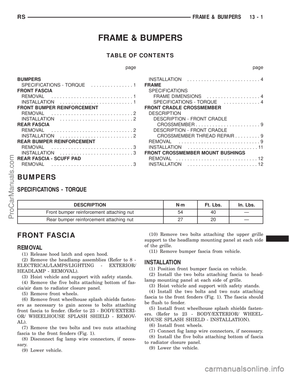
FRAME & BUMPERS
TABLE OF CONTENTS
page page
BUMPERS
SPECIFICATIONS - TORQUE...............1
FRONT FASCIA
REMOVAL.............................1
INSTALLATION..........................1
FRONT BUMPER REINFORCEMENT
REMOVAL.............................2
INSTALLATION..........................2
REAR FASCIA
REMOVAL.............................2
INSTALLATION..........................2
REAR BUMPER REINFORCEMENT
REMOVAL.............................3
INSTALLATION..........................3
REAR FASCIA - SCUFF PAD
REMOVAL.............................3INSTALLATION..........................4
FRAME
SPECIFICATIONS
FRAME DIMENSIONS...................4
SPECIFICATIONS - TORQUE.............4
FRONT CRADLE CROSSMEMBER
DESCRIPTION
DESCRIPTION - FRONT CRADLE
CROSSMEMBER.......................9
DESCRIPTION - FRONT CRADLE
CROSSMEMBER THREAD REPAIR.........9
REMOVAL.............................9
INSTALLATION.........................11
FRONT CROSSMEMBER MOUNT BUSHINGS
REMOVAL.............................12
INSTALLATION.........................12
BUMPERS
SPECIFICATIONS - TORQUE
DESCRIPTION N´m Ft. Lbs. In. Lbs.
Front bumper reinforcement attaching nut 54 40 Ð
Rear bumper reinforcement attaching nut 27 20 Ð
FRONT FASCIA
REMOVAL
(1) Release hood latch and open hood.
(2) Remove the headlamp assemblies (Refer to 8 -
ELECTRICAL/LAMPS/LIGHTING - EXTERIOR/
HEADLAMP - REMOVAL).
(3) Hoist vehicle and support with safety stands.
(4) Remove the five bolts attaching bottom of fas-
cia/air dam to radiator closure panel.
(5) Remove front wheels.
(6) Remove front wheelhouse splash shields fasten-
ers as necessary to gain access to bolts attaching
front fascia to fender. (Refer to 23 - BODY/EXTERI-
OR/ WHEELHOUSE SPLASH SHIELD - REMOV-
AL).
(7) Remove the two bolts and two nuts attaching
fascia to the front fenders (Fig. 1).
(8) Disconnect fog lamp wire connectors, if neces-
sary.
(9) Lower vehicle.(10) Remove two bolts attaching the upper grille
support to the headlamp mounting panel at each side
of the grille.
(11) Remove bumper fascia from vehicle.
INSTALLATION
(1) Position front bumper fascia on vehicle.
(2) Install the two bolts attaching fascia to head-
lamp mounting panel at each side of grille.
(3) Hoist vehicle and support with safety stands.
(4) Install the two bolts and two nuts attaching
fascia to the front fenders (Fig. 1). The fascia should
be flush to fender.
(5) Install front wheelhouse splash shields fasten-
ers. (Refer to 23 - BODY/EXTERIOR/ WHEEL-
HOUSE SPLASH SHIELD - INSTALLATION).
(6) Install front wheels.
(7) Connect fog lamp wire connectors, if necessary.
(8) Install the five bolts attaching bottom of fascia
to radiator closure panel.
(9) Lower the vehicle.
RSFRAME & BUMPERS13-1
ProCarManuals.com
Page 1351 of 2177
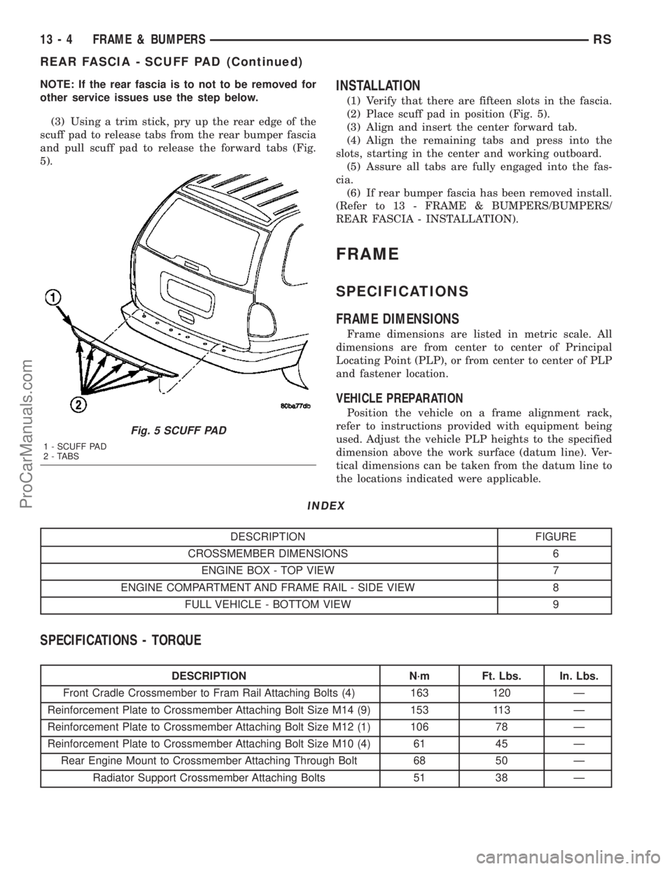
NOTE: If the rear fascia is to not to be removed for
other service issues use the step below.
(3) Using a trim stick, pry up the rear edge of the
scuff pad to release tabs from the rear bumper fascia
and pull scuff pad to release the forward tabs (Fig.
5).INSTALLATION
(1) Verify that there are fifteen slots in the fascia.
(2) Place scuff pad in position (Fig. 5).
(3) Align and insert the center forward tab.
(4) Align the remaining tabs and press into the
slots, starting in the center and working outboard.
(5) Assure all tabs are fully engaged into the fas-
cia.
(6) If rear bumper fascia has been removed install.
(Refer to 13 - FRAME & BUMPERS/BUMPERS/
REAR FASCIA - INSTALLATION).
FRAME
SPECIFICATIONS
FRAME DIMENSIONS
Frame dimensions are listed in metric scale. All
dimensions are from center to center of Principal
Locating Point (PLP), or from center to center of PLP
and fastener location.
VEHICLE PREPARATION
Position the vehicle on a frame alignment rack,
refer to instructions provided with equipment being
used. Adjust the vehicle PLP heights to the specified
dimension above the work surface (datum line). Ver-
tical dimensions can be taken from the datum line to
the locations indicated were applicable.
INDEX
DESCRIPTION FIGURE
CROSSMEMBER DIMENSIONS 6
ENGINE BOX - TOP VIEW 7
ENGINE COMPARTMENT AND FRAME RAIL - SIDE VIEW 8
FULL VEHICLE - BOTTOM VIEW 9
SPECIFICATIONS - TORQUE
DESCRIPTION N´m Ft. Lbs. In. Lbs.
Front Cradle Crossmember to Fram Rail Attaching Bolts (4) 163 120 Ð
Reinforcement Plate to Crossmember Attaching Bolt Size M14 (9) 153 113 Ð
Reinforcement Plate to Crossmember Attaching Bolt Size M12 (1) 106 78 Ð
Reinforcement Plate to Crossmember Attaching Bolt Size M10 (4) 61 45 Ð
Rear Engine Mount to Crossmember Attaching Through Bolt 68 50 Ð
Radiator Support Crossmember Attaching Bolts 51 38 Ð
Fig. 5 SCUFF PAD
1 - SCUFF PAD
2 - TABS
13 - 4 FRAME & BUMPERSRS
REAR FASCIA - SCUFF PAD (Continued)
ProCarManuals.com
Page 1407 of 2177
WARNING: THE AIR BAG SYSTEM IS A SENSITIVE,
COMPLEX ELECTRO-MECHANICAL UNIT. BEFORE
ATTEMPTING TO DIAGNOSE, REMOVE OR INSTALL
THE AIR BAG SYSTEM COMPONENTS YOU MUST
FIRST DISCONNECT AND ISOLATE THE BATTERY
NEGATIVE (GROUND) CABLE. THEN WAIT TWO
MINUTES FOR THE SYSTEM CAPACITOR TO DIS-
CHARGE. FAILURE TO DO SO COULD RESULT IN
ACCIDENTAL DEPLOYMENT OF THE AIR BAG AND
POSSIBLE PERSONAL INJURY. THE FASTENERS,
SCREWS, AND BOLTS, ORIGINALLY USED FOR
THE AIR BAG COMPONENTS, HAVE SPECIAL
COATINGS AND ARE SPECIFICALLY DESIGNED
FOR THE AIR BAG SYSTEM. THEY MUST NEVER
BE REPLACED WITH ANY SUBSTITUTES. ANYTIME
A NEW FASTENER IS NEEDED, REPLACE WITH
THE CORRECT FASTENERS PROVIDED IN THE
SERVICE PACKAGE OR FASTENERS LISTED IN
THE PARTS BOOKS.
WARNING: SAFETY GOGGLES SHOULD BE WORN
AT ALL TIMES WHEN WORKING ON STEERING
COLUMNS.
CAUTION: Disconnect negative (ground) cable from
the battery before servicing any column compo-
nent.
CAUTION: Do not attempt to remove the pivot pins
to disassemble the tilting mechanism. Damage will
occur.
DIAGNOSIS AND TESTING - STEERING
COLUMN
For diagnosis of conditions relating to the steering
column (Refer to 19 - STEERING - DIAGNOSIS AND
TESTING) and (Refer to 19 - STEERING - DIAGNO-
SIS AND TESTING).
REMOVAL
NOTE: Before proceeding, (Refer to 19 - STEERING/
COLUMN - WARNING).
(1) Make sure the front wheels of the vehicle are
in the STRAIGHT AHEAD position before beginning
the column removal procedure.
(2) Disconnect negative (ground) cable from the
battery and isolate cable from battery terminal.
(3) Remove the lower shroud (Refer to 19 -
STEERING/COLUMN/LOWER SHROUD - REMOV-
AL).
(4) Remove the traction off switch.
(5) Remove the upper shroud.
(6) Remove the cluster trim bezel (Refer to 23 -
BODY/INSTRUMENT PANEL/CLUSTER BEZEL -
REMOVAL).
(7) Remove the knee blocker (Refer to 23 - BODY/
INSTRUMENT PANEL/STEERING COLUMN
OPENING COVER - REMOVAL).
(8) Remove the parking brake handle link.
(9) Remove the knee blocker reinforcement (Refer
to 23 - BODY/INSTRUMENT PANEL/KNEE
BLOCKER - REMOVAL).
(10) Remove the airbag (Refer to 8 - ELECTRI-
CAL/RESTRAINTS/DRIVER AIRBAG - REMOVAL).
(11) Remove the steering wheel retaining nut.
(12) Remove the vibration damper weight.
(13) Remove the steering wheel (Refer to 19 -
STEERING/COLUMN/STEERING WHEEL -
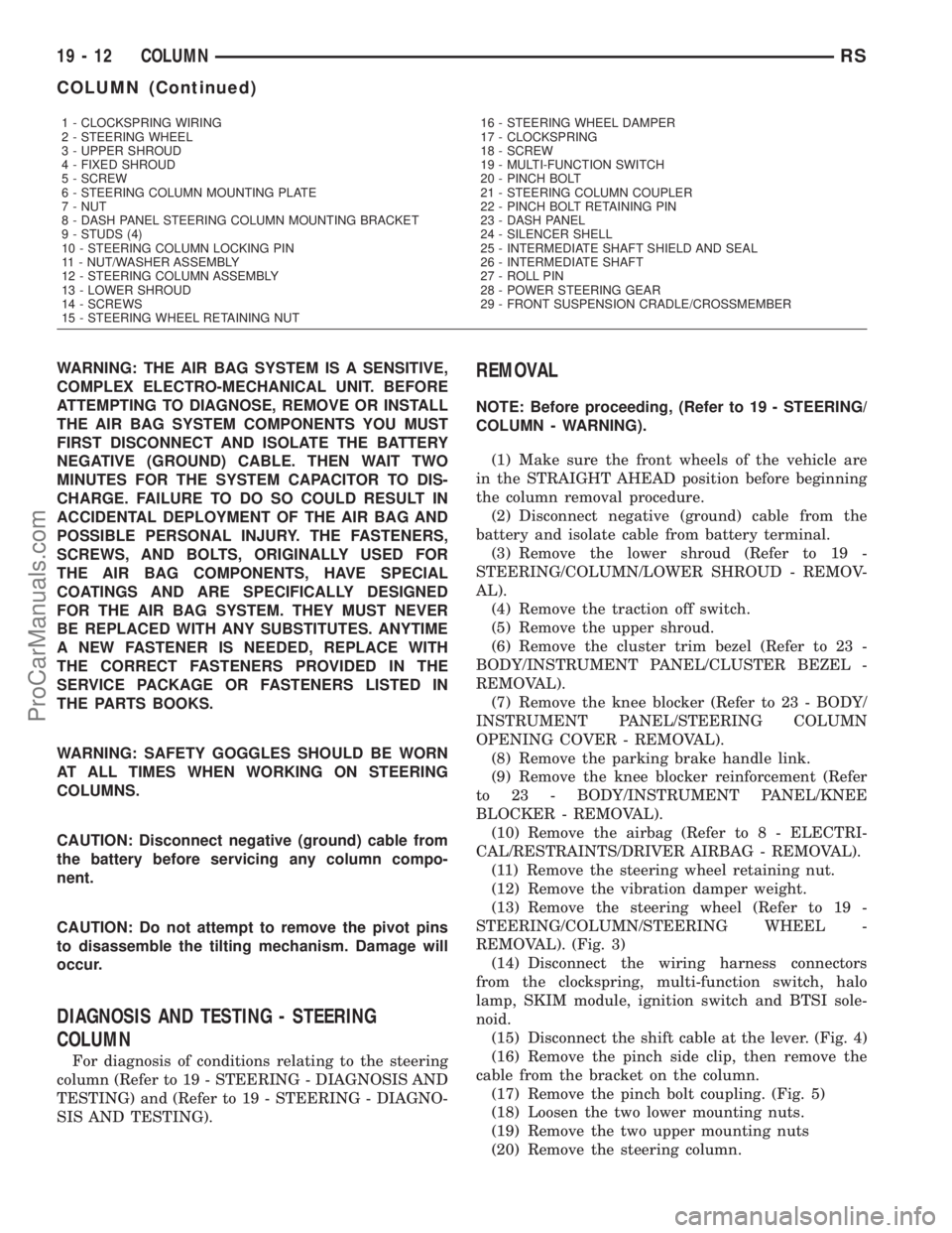
REMOVAL). (Fig. 3)
(14) Disconnect the wiring harness connectors
from the clockspring, multi-function switch, halo
lamp, SKIM module, ignition switch and BTSI sole-
noid.
(15) Disconnect the shift cable at the lever. (Fig. 4)
(16) Remove the pinch side clip, then remove the
cable from the bracket on the column.
(17) Remove the pinch bolt coupling. (Fig. 5)
(18) Loosen the two lower mounting nuts.
(19) Remove the two upper mounting nuts
(20) Remove the steering column.
1 - CLOCKSPRING WIRING
2 - STEERING WHEEL
3 - UPPER SHROUD
4 - FIXED SHROUD
5 - SCREW
6 - STEERING COLUMN MOUNTING PLATE
7 - NUT
8 - DASH PANEL STEERING COLUMN MOUNTING BRACKET
9 - STUDS (4)
10 - STEERING COLUMN LOCKING PIN
11 - NUT/WASHER ASSEMBLY
12 - STEERING COLUMN ASSEMBLY
13 - LOWER SHROUD
14 - SCREWS
15 - STEERING WHEEL RETAINING NUT16 - STEERING WHEEL DAMPER
17 - CLOCKSPRING
18 - SCREW
19 - MULTI-FUNCTION SWITCH
20 - PINCH BOLT
21 - STEERING COLUMN COUPLER
22 - PINCH BOLT RETAINING PIN
23 - DASH PANEL
24 - SILENCER SHELL
25 - INTERMEDIATE SHAFT SHIELD AND SEAL
26 - INTERMEDIATE SHAFT
27 - ROLL PIN
28 - POWER STEERING GEAR
29 - FRONT SUSPENSION CRADLE/CROSSMEMBER
19 - 12 COLUMNRS
COLUMN (Continued)
ProCarManuals.com
Page 1423 of 2177
(5) Raise vehicle. (Refer to LUBRICATION &
MAINTENANCE/HOISTING - STANDARD PROCE-
DURE)
(6) Remove front wheel and tire assemblies.
(7) Remove front emissions vapor canister. (Refer
to 25 - EMISSIONS CONTROL/EVAPORATIVE
EMISSIONS/VAPOR CANISTER - REMOVAL)
(8) Remove a single hose at power steering cooler
and allow fluid to drain.
(9) Remove 2 bolts attaching power steering cooler
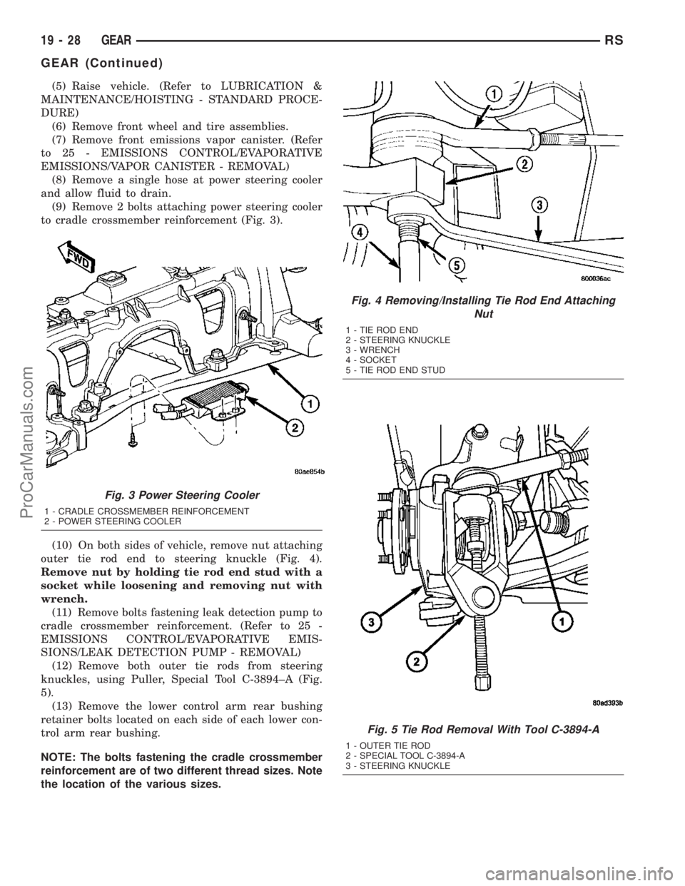
to cradle crossmember reinforcement (Fig. 3).
(10) On both sides of vehicle, remove nut attaching
outer tie rod end to steering knuckle (Fig. 4).
Remove nut by holding tie rod end stud with a
socket while loosening and removing nut with
wrench.
(11) Remove bolts fastening leak detection pump to
cradle crossmember reinforcement. (Refer to 25 -
EMISSIONS CONTROL/EVAPORATIVE EMIS-
SIONS/LEAK DETECTION PUMP - REMOVAL)
(12) Remove both outer tie rods from steering
knuckles, using Puller, Special Tool C-3894±A (Fig.
5).
(13) Remove the lower control arm rear bushing
retainer bolts located on each side of each lower con-
trol arm rear bushing.
NOTE: The bolts fastening the cradle crossmember
reinforcement are of two different thread sizes. Note
the location of the various sizes.
Fig. 3 Power Steering Cooler
1 - CRADLE CROSSMEMBER REINFORCEMENT
2 - POWER STEERING COOLER
Fig. 4 Removing/Installing Tie Rod End Attaching
Nut
1 - TIE ROD END
2 - STEERING KNUCKLE
3 - WRENCH
4 - SOCKET
5 - TIE ROD END STUD
Fig. 5 Tie Rod Removal With Tool C-3894-A
1 - OUTER TIE ROD
2 - SPECIAL TOOL C-3894-A
3 - STEERING KNUCKLE
19 - 28 GEARRS
GEAR (Continued)
ProCarManuals.com
Page 1424 of 2177
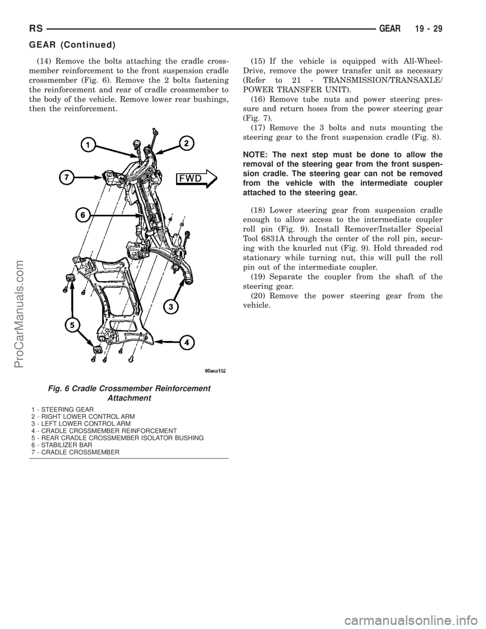
(14) Remove the bolts attaching the cradle cross-
member reinforcement to the front suspension cradle
crossmember (Fig. 6). Remove the 2 bolts fastening
the reinforcement and rear of cradle crossmember to
the body of the vehicle. Remove lower rear bushings,
then the reinforcement.(15) If the vehicle is equipped with All-Wheel-
Drive, remove the power transfer unit as necessary
(Refer to 21 - TRANSMISSION/TRANSAXLE/
POWER TRANSFER UNIT).
(16) Remove tube nuts and power steering pres-
sure and return hoses from the power steering gear
(Fig. 7).
(17) Remove the 3 bolts and nuts mounting the
steering gear to the front suspension cradle (Fig. 8).
NOTE: The next step must be done to allow the
removal of the steering gear from the front suspen-
sion cradle. The steering gear can not be removed
from the vehicle with the intermediate coupler
attached to the steering gear.
(18) Lower steering gear from suspension cradle
enough to allow access to the intermediate coupler
roll pin (Fig. 9). Install Remover/Installer Special
Tool 6831A through the center of the roll pin, secur-
ing with the knurled nut (Fig. 9). Hold threaded rod
stationary while turning nut, this will pull the roll
pin out of the intermediate coupler.
(19) Separate the coupler from the shaft of the
steering gear.
(20) Remove the power steering gear from the
vehicle.
Fig. 6 Cradle Crossmember Reinforcement
Attachment
1 - STEERING GEAR
2 - RIGHT LOWER CONTROL ARM
3 - LEFT LOWER CONTROL ARM
4 - CRADLE CROSSMEMBER REINFORCEMENT
5 - REAR CRADLE CROSSMEMBER ISOLATOR BUSHING
6 - STABILIZER BAR
7 - CRADLE CROSSMEMBER
RSGEAR19-29
GEAR (Continued)
ProCarManuals.com