2003 CHRYSLER VOYAGER ABS
[x] Cancel search: ABSPage 1417 of 2177
(3) Unsnap the upper shroud from the lower on
the right side as follows:
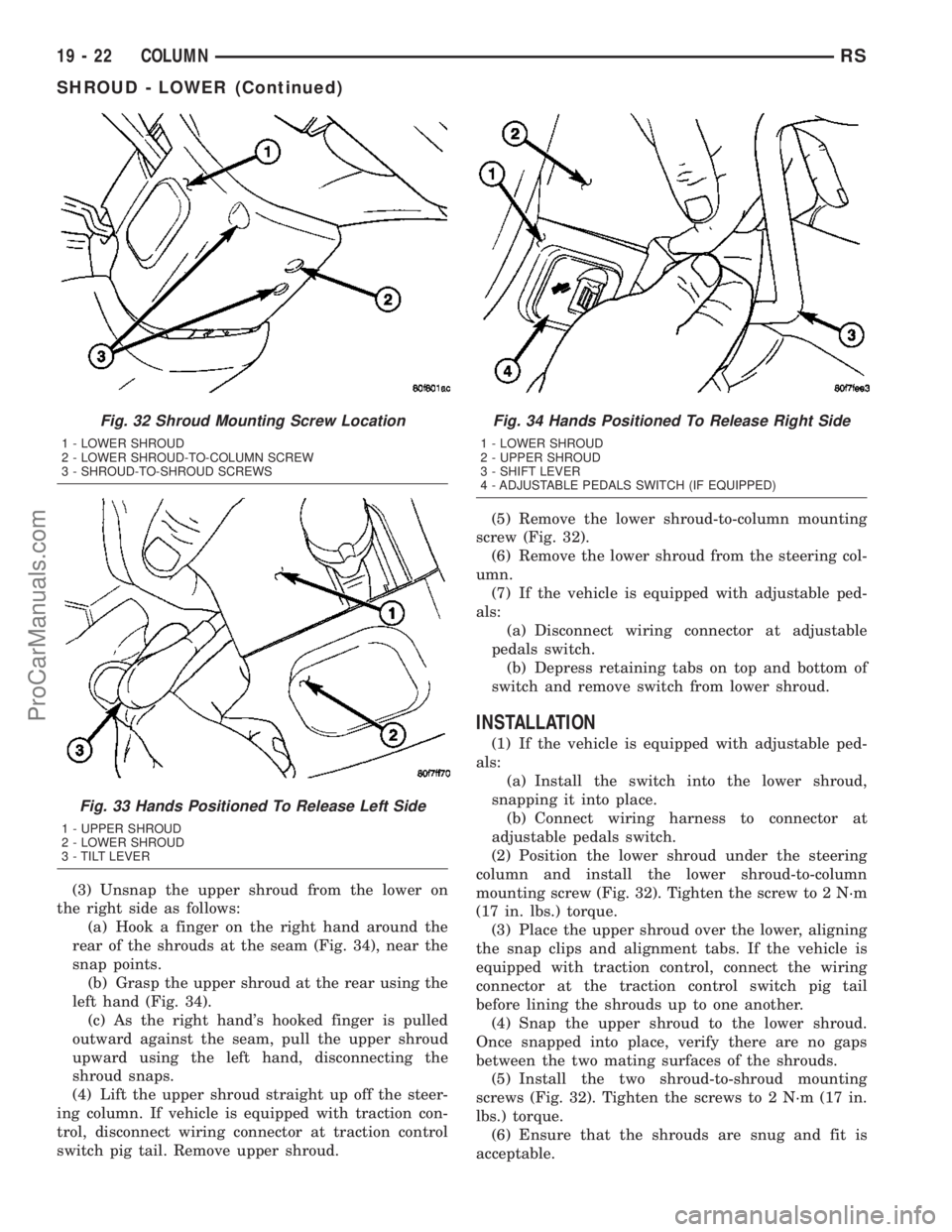
(a) Hook a finger on the right hand around the
rear of the shrouds at the seam (Fig. 34), near the
snap points.
(b) Grasp the upper shroud at the rear using the
left hand (Fig. 34).
(c) As the right hand's hooked finger is pulled
outward against the seam, pull the upper shroud
upward using the left hand, disconnecting the
shroud snaps.
(4) Lift the upper shroud straight up off the steer-
ing column. If vehicle is equipped with traction con-
trol, disconnect wiring connector at traction control
switch pig tail. Remove upper shroud.(5) Remove the lower shroud-to-column mounting
screw (Fig. 32).
(6) Remove the lower shroud from the steering col-
umn.
(7) If the vehicle is equipped with adjustable ped-
als:
(a) Disconnect wiring connector at adjustable
pedals switch.
(b) Depress retaining tabs on top and bottom of
switch and remove switch from lower shroud.
INSTALLATION
(1) If the vehicle is equipped with adjustable ped-
als:
(a) Install the switch into the lower shroud,
snapping it into place.
(b) Connect wiring harness to connector at
adjustable pedals switch.
(2) Position the lower shroud under the steering
column and install the lower shroud-to-column
mounting screw (Fig. 32). Tighten the screw to 2 N´m
(17 in. lbs.) torque.
(3) Place the upper shroud over the lower, aligning
the snap clips and alignment tabs. If the vehicle is
equipped with traction control, connect the wiring
connector at the traction control switch pig tail
before lining the shrouds up to one another.
(4) Snap the upper shroud to the lower shroud.
Once snapped into place, verify there are no gaps
between the two mating surfaces of the shrouds.
(5) Install the two shroud-to-shroud mounting
screws (Fig. 32). Tighten the screws to 2 N´m (17 in.
lbs.) torque.
(6) Ensure that the shrouds are snug and fit is
acceptable.
Fig. 32 Shroud Mounting Screw Location
1 - LOWER SHROUD
2 - LOWER SHROUD-TO-COLUMN SCREW
3 - SHROUD-TO-SHROUD SCREWS
Fig. 33 Hands Positioned To Release Left Side
1 - UPPER SHROUD
2 - LOWER SHROUD
3 - TILT LEVER
Fig. 34 Hands Positioned To Release Right Side
1 - LOWER SHROUD
2 - UPPER SHROUD
3 - SHIFT LEVER
4 - ADJUSTABLE PEDALS SWITCH (IF EQUIPPED)
19 - 22 COLUMNRS
SHROUD - LOWER (Continued)
ProCarManuals.com
Page 1418 of 2177
SHROUD - UPPER
REMOVAL
(1) Remove the two shroud-to-shroud mounting
screws from the lower shroud (Fig. 32).
(2) Unsnap the upper shroud from the lower on
the left side as follows:
(a) Hook a finger on the left hand around the
rear of the shrouds at the seam (Fig. 33), near the
snap points.
(b) Grasp the upper shroud at the rear using the
right hand (Fig. 33).
(c) As the left hand's hooked finger is pulled out-
ward against the seam, pull the upper shroud
upward using the right hand, disconnecting the
shroud snaps.
(3) Unsnap the upper shroud from the lower on
the right side as follows:
(a) Hook a finger on the right hand around the
rear of the shrouds at the seam (Fig. 34), near the
snap points.
(b) Grasp the upper shroud at the rear using the
left hand (Fig. 34).
(c) As the right hand's hooked finger is pulled
outward against the seam, pull the upper shroud
upward using the left hand, disconnecting the
shroud snaps.
(4) Lift the upper shroud straight up off the steer-
ing column. If vehicle is equipped with traction con-
trol, disconnect wiring connector at traction control
switch pig tail. If vehicle is equipped with power fold-
away mirrors (Export), disconnect wiring connector
at mirror switch pig tail. Remove upper shroud.
(5) If vehicle is equipped with traction control,
remove traction control switch from shroud.
(6) If vehicle is equipped with power foldaway mir-
rors (Export), remove power fold-away switch from
upper shroud.
INSTALLATION
(1) If the vehicle is equipped with power foldaway
mirrors (Export), install the power fold-away switch
in the upper shroud.
(2) If vehicle is equipped with traction control,
install the traction control switch in the upper
shroud.
(3) Place the upper shroud over the lower shroud,
aligning the snap clips and alignment tabs. If the
vehicle is equipped with traction control, connect the
wiring connector at the traction control switch pig
tail before lining the shrouds up to one another.
(4) Snap the upper shroud to the lower shroud.
Once snapped into place, verify there are no gaps
between the two mating surfaces of the shrouds.(5) Install the two shroud-to-shroud mounting
screws (Fig. 32). Tighten the screws to 2 N´m (17 in.
lbs.) torque.
(6) Ensure that the shrouds are snug and fit is
acceptable.
STEERING WHEEL
REMOVAL
NOTE: Before proceeding, (Refer to 19 - STEERING/
COLUMN - WARNING)(Refer to 8 - ELECTRICAL/RE-
STRAINTS - WARNING).
(1) Adjust the steering wheel so that the tires are
in thestraight-aheadposition.
(2) Disconnect and isolate the battery negative
cable.
(3) Remove the two bolts from the rear of the
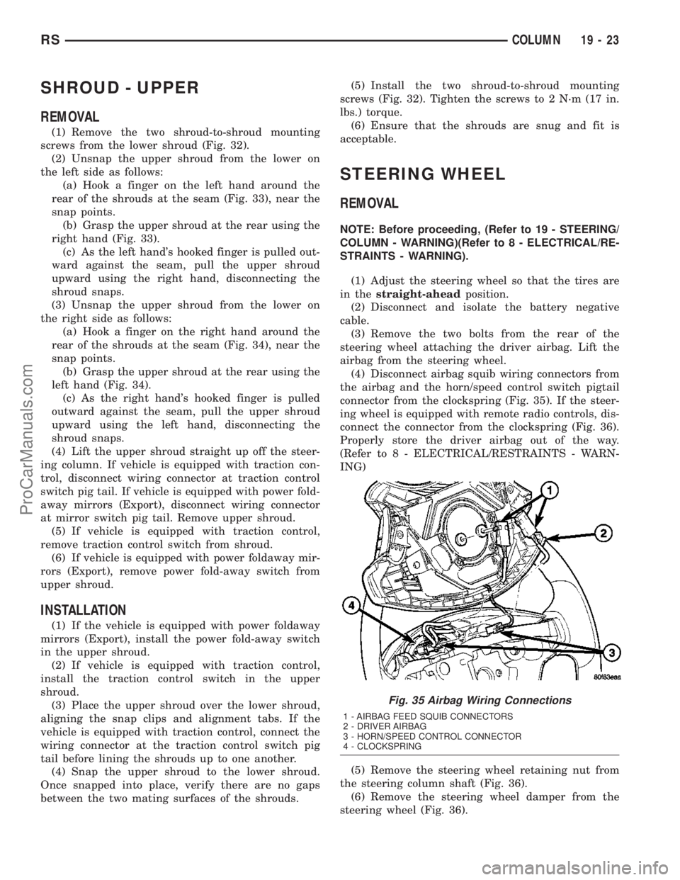
steering wheel attaching the driver airbag. Lift the
airbag from the steering wheel.
(4) Disconnect airbag squib wiring connectors from
the airbag and the horn/speed control switch pigtail
connector from the clockspring (Fig. 35). If the steer-
ing wheel is equipped with remote radio controls, dis-
connect the connector from the clockspring (Fig. 36).
Properly store the driver airbag out of the way.
(Refer to 8 - ELECTRICAL/RESTRAINTS - WARN-
ING)
(5) Remove the steering wheel retaining nut from
the steering column shaft (Fig. 36).
(6) Remove the steering wheel damper from the
steering wheel (Fig. 36).
Fig. 35 Airbag Wiring Connections
1 - AIRBAG FEED SQUIB CONNECTORS
2 - DRIVER AIRBAG
3 - HORN/SPEED CONTROL CONNECTOR
4 - CLOCKSPRING
RSCOLUMN19-23
ProCarManuals.com
Page 1425 of 2177
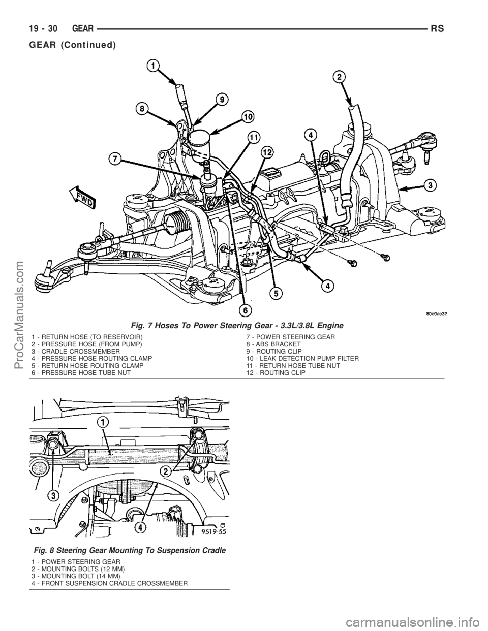
Fig. 7 Hoses To Power Steering Gear - 3.3L/3.8L Engine
1 - RETURN HOSE (TO RESERVOIR)
2 - PRESSURE HOSE (FROM PUMP)
3 - CRADLE CROSSMEMBER
4 - PRESSURE HOSE ROUTING CLAMP
5 - RETURN HOSE ROUTING CLAMP
6 - PRESSURE HOSE TUBE NUT7 - POWER STEERING GEAR
8 - ABS BRACKET
9 - ROUTING CLIP
10 - LEAK DETECTION PUMP FILTER
11 - RETURN HOSE TUBE NUT
12 - ROUTING CLIP
Fig. 8 Steering Gear Mounting To Suspension Cradle
1 - POWER STEERING GEAR
2 - MOUNTING BOLTS (12 MM)
3 - MOUNTING BOLT (14 MM)
4 - FRONT SUSPENSION CRADLE CROSSMEMBER
19 - 30 GEARRS
GEAR (Continued)
ProCarManuals.com
Page 1439 of 2177
FLUID
STANDARD PROCEDURE - POWER STEERING
FLUID LEVEL CHECKING
WARNING: FLUID LEVEL SHOULD BE CHECKED
WITH THE ENGINE OFF TO PREVENT INJURY
FROM MOVING PARTS AND TO ENSURE ACCU-
RATE FLUID LEVEL READING.
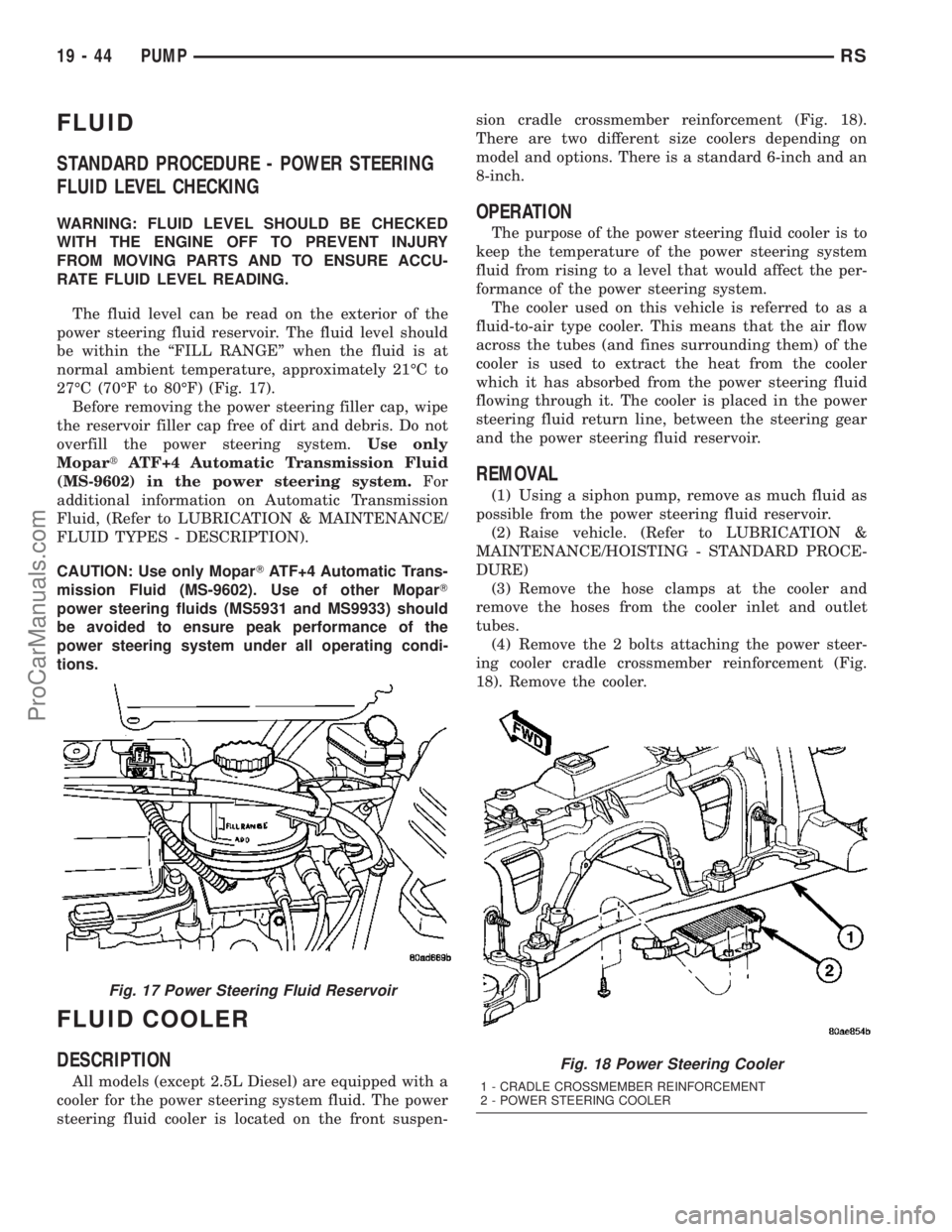
The fluid level can be read on the exterior of the
power steering fluid reservoir. The fluid level should
be within the ªFILL RANGEº when the fluid is at
normal ambient temperature, approximately 21ÉC to
27ÉC (70ÉF to 80ÉF) (Fig. 17).
Before removing the power steering filler cap, wipe
the reservoir filler cap free of dirt and debris. Do not
overfill the power steering system.Use only
MopartATF+4 Automatic Transmission Fluid
(MS-9602) in the power steering system.For
additional information on Automatic Transmission
Fluid, (Refer to LUBRICATION & MAINTENANCE/
FLUID TYPES - DESCRIPTION).
CAUTION: Use only MoparTATF+4 Automatic Trans-
mission Fluid (MS-9602). Use of other MoparT
power steering fluids (MS5931 and MS9933) should
be avoided to ensure peak performance of the
power steering system under all operating condi-
tions.
FLUID COOLER
DESCRIPTION
All models (except 2.5L Diesel) are equipped with a
cooler for the power steering system fluid. The power
steering fluid cooler is located on the front suspen-sion cradle crossmember reinforcement (Fig. 18).
There are two different size coolers depending on
model and options. There is a standard 6-inch and an
8-inch.
OPERATION
The purpose of the power steering fluid cooler is to
keep the temperature of the power steering system
fluid from rising to a level that would affect the per-
formance of the power steering system.
The cooler used on this vehicle is referred to as a
fluid-to-air type cooler. This means that the air flow
across the tubes (and fines surrounding them) of the
cooler is used to extract the heat from the cooler
which it has absorbed from the power steering fluid
flowing through it. The cooler is placed in the power
steering fluid return line, between the steering gear
and the power steering fluid reservoir.
REMOVAL
(1) Using a siphon pump, remove as much fluid as
possible from the power steering fluid reservoir.
(2) Raise vehicle. (Refer to LUBRICATION &
MAINTENANCE/HOISTING - STANDARD PROCE-
DURE)
(3) Remove the hose clamps at the cooler and
remove the hoses from the cooler inlet and outlet
tubes.
(4) Remove the 2 bolts attaching the power steer-
ing cooler cradle crossmember reinforcement (Fig.
18). Remove the cooler.
Fig. 17 Power Steering Fluid Reservoir
Fig. 18 Power Steering Cooler
1 - CRADLE CROSSMEMBER REINFORCEMENT
2 - POWER STEERING COOLER
19 - 44 PUMPRS
ProCarManuals.com
Page 1441 of 2177
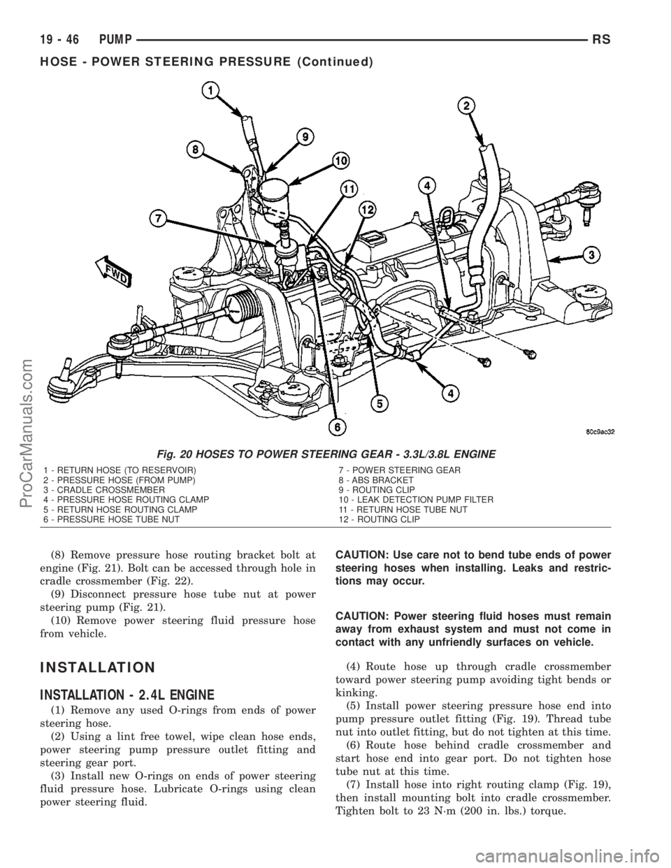
(8) Remove pressure hose routing bracket bolt at
engine (Fig. 21). Bolt can be accessed through hole in
cradle crossmember (Fig. 22).
(9) Disconnect pressure hose tube nut at power
steering pump (Fig. 21).
(10) Remove power steering fluid pressure hose
from vehicle.
INSTALLATION
INSTALLATION - 2.4L ENGINE
(1) Remove any used O-rings from ends of power
steering hose.
(2) Using a lint free towel, wipe clean hose ends,
power steering pump pressure outlet fitting and
steering gear port.
(3) Install new O-rings on ends of power steering
fluid pressure hose. Lubricate O-rings using clean
power steering fluid.CAUTION: Use care not to bend tube ends of power
steering hoses when installing. Leaks and restric-
tions may occur.
CAUTION: Power steering fluid hoses must remain
away from exhaust system and must not come in
contact with any unfriendly surfaces on vehicle.
(4) Route hose up through cradle crossmember
toward power steering pump avoiding tight bends or
kinking.
(5) Install power steering pressure hose end into
pump pressure outlet fitting (Fig. 19). Thread tube
nut into outlet fitting, but do not tighten at this time.
(6) Route hose behind cradle crossmember and
start hose end into gear port. Do not tighten hose
tube nut at this time.
(7) Install hose into right routing clamp (Fig. 19),
then install mounting bolt into cradle crossmember.
Tighten bolt to 23 N´m (200 in. lbs.) torque.
Fig. 20 HOSES TO POWER STEERING GEAR - 3.3L/3.8L ENGINE
1 - RETURN HOSE (TO RESERVOIR)
2 - PRESSURE HOSE (FROM PUMP)
3 - CRADLE CROSSMEMBER
4 - PRESSURE HOSE ROUTING CLAMP
5 - RETURN HOSE ROUTING CLAMP
6 - PRESSURE HOSE TUBE NUT7 - POWER STEERING GEAR
8 - ABS BRACKET
9 - ROUTING CLIP
10 - LEAK DETECTION PUMP FILTER
11 - RETURN HOSE TUBE NUT
12 - ROUTING CLIP
19 - 46 PUMPRS
HOSE - POWER STEERING PRESSURE (Continued)
ProCarManuals.com
Page 1443 of 2177
CAUTION: Use care not to bend tube ends of the
power steering hoses when installing. Leaks and
restrictions may occur.
CAUTION: Power steering fluid hoses must remain
away from the exhaust system and must not come
in contact with any unfriendly surfaces on the vehi-
cle.
(4) Route hose up behind engine toward pump
avoiding tight bends or kinking.
(5) Install power steering pressure hose end into
pump pressure outlet fitting (Fig. 21). Thread tube
nut into outlet fitting, but do not tighten at this time.
(6) Attach pressure hose routing bracket to engine
(Fig. 21). Tighten bolt to 23 N´m (200 in. lbs.) torque.
(7) Tighten hose tube nut at pump outlet fitting to
31 N´m (275 in. lbs.) torque.
(8) Route hose behind cradle crossmember and
start hose end into gear port. Do not tighten hose
tube nut at this time.
(9) Attach hose to suspension cradle crossmember
and steel reinforcement using two routing clamps
and bolts (Fig. 20). Tighten clamp bolt at steel rein-
forcement to 11 N´m (100 in. lbs.) torque. Tighten
clamp bolt at cradle crossmember to 23 N´m (200 in.
lbs.) torque.
(10) Tighten hose tube nut at power steering gear
port to 31 N´m (275 in. lbs.) torque.
(11) Install front emissions vapor canister. (Refer
to 25 - EMISSIONS CONTROL/EVAPORATIVE
EMISSIONS/VAPOR CANISTER - INSTALLATION)
(12) Lower vehicle.
(13) Fill and bleed the power steering system
using the Power Steering Pump Initial Operation
Procedure. (Refer to 19 - STEERING/PUMP - STAN-
DARD PROCEDURE)
(14) Inspect system for leaks.
HOSE - POWER STEERING
RETURN
REMOVAL
REMOVAL - 2.4L ENGINE
NOTE: Before proceeding, review all WARNINGS
and CAUTIONS. (Refer to 19 - STEERING/PUMP -
WARNING)(Refer to 19 - STEERING/PUMP - CAU-
TION)
(1) Remove cap from power steering fluid reser-
voir.(2) Using a siphon pump, remove as much power
steering fluid as possible from power steering fluid
reservoir.
(3) Raise vehicle. (Refer to LUBRICATION &
MAINTENANCE/HOISTING - STANDARD PROCE-
DURE)
(4) Remove front emissions vapor canister. (Refer
to 25 - EMISSIONS CONTROL/EVAPORATIVE
EMISSIONS/VAPOR CANISTER - REMOVAL)
(5) Place an oil drain pan under vehicle to catch
power steering fluid.
(6) Cut tie-strap securing insulating heat sleeve to
power steering fluid return hose near power steering
pump. Pull back heat sleeve to expose hose clamp.
(7) Remove clamp, then return hose from power
steering pump (Fig. 19).
(8) Remove 2 bolts attaching power steering cooler
to cradle crossmember reinforcement (Fig. 23).
(9) Remove bolts attaching routing clamps to front
suspension cradle crossmember (Fig. 19). Remove
return hose from clamps.
(10) Back out return hose tube nut at power steer-
ing gear and remove hose (Fig. 19).
REMOVAL - 3.3L/3.8L ENGINE
NOTE: Before proceeding, review all WARNINGS
and CAUTIONS. (Refer to 19 - STEERING/PUMP -
WARNING)(Refer to 19 - STEERING/PUMP - CAU-
TION)
(1) Remove cap from power steering fluid reser-
voir.
(2) Using a siphon pump, remove as much power
steering fluid as possible from power steering fluid
reservoir.
(3) Place an oil drain pan under vehicle to catch
any draining power steering fluid.
(4) Remove clamp attaching return hose to power
steering fluid reservoir. Disconnect hose from reser-
voir (Fig. 21).
(5) Follow return hose downward and open
retainer at ABS bracket (Fig. 20). Remove hose tube
from retainer.
(6) Raise vehicle. (Refer to LUBRICATION &
MAINTENANCE/HOISTING - STANDARD PROCE-
DURE)
(7) Remove front emissions vapor canister. (Refer
to 25 - EMISSIONS CONTROL/EVAPORATIVE
EMISSIONS/VAPOR CANISTER - REMOVAL)
(8) Remove bolt securing return hose routing
clamp to suspension cradle crossmember (Fig. 20).
(9) Remove 2 bolts attaching power steering cooler
to cradle crossmember reinforcement (Fig. 23).
(10) Disconnect return hose at power steering gear
(Fig. 20).
19 - 48 PUMPRS
HOSE - POWER STEERING PRESSURE (Continued)
ProCarManuals.com
Page 1445 of 2177
(6) Attach return hose tubes to suspension cradle
crossmember using routing clamp and bolt (Fig. 20).
Tighten clamp bolt to 23 N´m (200 in. lbs.) torque.
(7) Install the power steering fluid cooler on the
cradle crossmember reinforcement (Fig. 23). Install
the mounting bolts and tighten to 11 N´m (100 in.
lbs.). When installing mounting bolts, include pres-
sure hose routing clamp.
(8) Tighten hose tube nut at power steering gear
port to 31 N´m (275 in. lbs.) torque.
(9) Install front emissions vapor canister. (Refer to
25 - EMISSIONS CONTROL/EVAPORATIVE EMIS-
SIONS/VAPOR CANISTER - INSTALLATION)
(10) Lower vehicle.
(11) Install return hose tube into retainer on ABS
bracket (Fig. 20). Close the bracket.
(12) Install return hose onto reservoir (Fig. 21).
Slide the hose clamp into position on fluid reservoir
and attach it.Be sure hose clamp in installed
past bead on fluid reservoir fitting.
(13) Fill and bleed power steering system using
the Power Steering Pump Initial Operation Proce-
dure. (Refer to 19 - STEERING/PUMP - STANDARD
PROCEDURE)
(14) Inspect system for leaks.
HOSE - POWER STEERING
SUPPLY
REMOVAL
REMOVAL - 2.4L ENGINE
(1) Remove filler cap from power steering fluid res-
ervoir.
(2) Using a siphon pump, remove as much power
steering fluid as possible from the power steering
fluid reservoir.
(3) Raise vehicle. (Refer to LUBRICATION &
MAINTENANCE/HOISTING - STANDARD PROCE-
DURE)
(4) Remove hose clamp securing supply hose to
power steering pump, then remove supply hose from
pump fitting.
(5) Lower vehicle.
(6) Remove hose clamp attaching power steering
fluid supply hose to power steering fluid reservoir,
then remove supply hose.
(7) Remove the power steering fluid supply hose
from the vehicle.
REMOVAL - 3.3L/3.8L ENGINE
NOTE: Before proceeding, review all WARNINGS
and CAUTIONS. (Refer to 19 - STEERING/PUMP -WARNING)(Refer to 19 - STEERING/PUMP - CAU-
TION)
(1) Remove cap from power steering fluid reser-
voir.
(2) Using a siphon pump, remove as much power
steering fluid as possible from power steering fluid
reservoir.
(3) Place an oil drain pan under vehicle to catch
any draining power steering fluid.
(4) Remove clamp attaching supply hose to power
steering fluid reservoir. Disconnect hose from reser-
voir (Fig. 21).
(5) Pull upward on hose routing clip releasing it
from bracket on cylinder head cover (Fig. 21).
NOTE: It may be necessary to remove air cleaner
housing to gain greater access to supply hose at
power steering pump. (Refer to 9 - ENGINE/AIR
INTAKE SYSTEM/AIR CLEANER HOUSING -
REMOVAL)
(6) Remove clamp attaching supply hose to power
steering pump. Disconnect hose from pump and
remove from vehicle (Fig. 21).
INSTALLATION
INSTALLATION - 2.4L ENGINE
(1) Install and correctly route power steering fluid
supply hose from remote fluid reservoir to power
steering pump.
(2) Install fluid supply hose onto power steering
fluid reservoir. Install hose clamp.Be sure hose
clamp is installed past bead on fluid reservoir
fitting.
(3) Raise vehicle. (Refer to LUBRICATION &
MAINTENANCE/HOISTING - STANDARD PROCE-
DURE)
(4) Install power steering fluid supply hose on
power steering pump supply fitting. Install hose
clamp.Be sure hose clamp is installed past bead
on pump fitting.
(5) Lower vehicle.
(6) Fill and bleed power steering system using
Power Steering Pump Initial Operation Procedure.
(Refer to 19 - STEERING/PUMP - STANDARD PRO-
CEDURE)
(7) Inspect system for leaks.
INSTALLATION - 3.3L/3.8L ENGINE
(1) Install supply hose onto supply fitting on power
steering pump (Fig. 21). Slide the hose clamp into
position on fluid reservoir and attach it.Be sure
hose clamp in installed past bead on fluid res-
ervoir fitting.
19 - 50 PUMPRS
HOSE - POWER STEERING RETURN (Continued)
ProCarManuals.com
Page 1555 of 2177
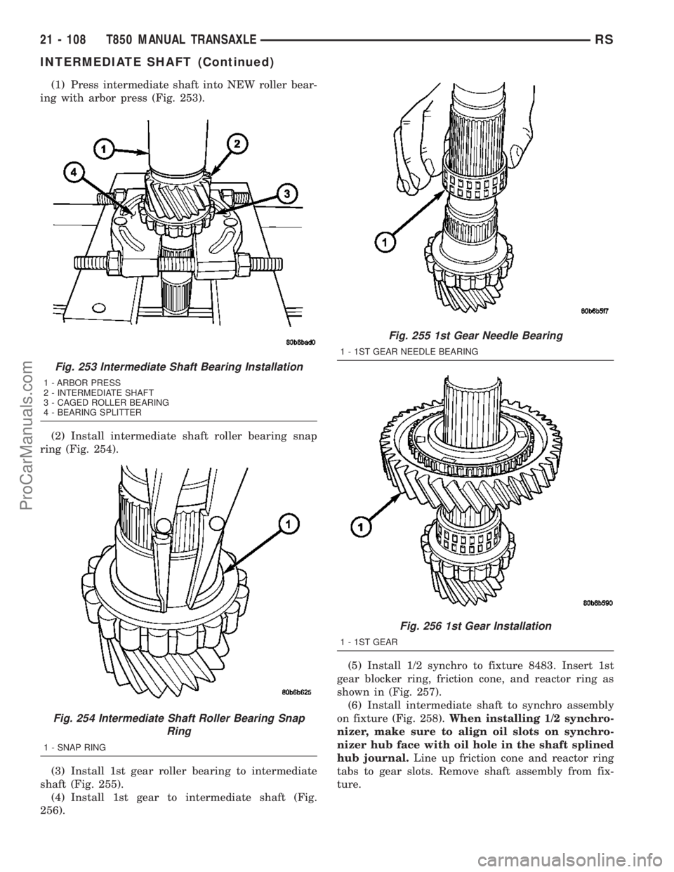
(1) Press intermediate shaft into NEW roller bear-
ing with arbor press (Fig. 253).
(2) Install intermediate shaft roller bearing snap
ring (Fig. 254).
(3) Install 1st gear roller bearing to intermediate
shaft (Fig. 255).
(4) Install 1st gear to intermediate shaft (Fig.
256).(5) Install 1/2 synchro to fixture 8483. Insert 1st
gear blocker ring, friction cone, and reactor ring as
shown in (Fig. 257).
(6) Install intermediate shaft to synchro assembly
on fixture (Fig. 258).When installing 1/2 synchro-
nizer, make sure to align oil slots on synchro-
nizer hub face with oil hole in the shaft splined
hub journal.Line up friction cone and reactor ring
tabs to gear slots. Remove shaft assembly from fix-
ture.
Fig. 253 Intermediate Shaft Bearing Installation
1 - ARBOR PRESS
2 - INTERMEDIATE SHAFT
3 - CAGED ROLLER BEARING
4 - BEARING SPLITTER
Fig. 254 Intermediate Shaft Roller Bearing Snap
Ring
1 - SNAP RING
Fig. 255 1st Gear Needle Bearing
1 - 1ST GEAR NEEDLE BEARING
Fig. 256 1st Gear Installation
1 - 1ST GEAR
21 - 108 T850 MANUAL TRANSAXLERS
INTERMEDIATE SHAFT (Continued)
ProCarManuals.com