2003 CHRYSLER VOYAGER ABS
[x] Cancel search: ABSPage 1381 of 2177
²Instrument Panel
²Body Control Module
²Air Bag System Diagnostic Module
²Full ATC Display Head (if equipped)
²ABS Module
²Transmission Control Module
²Powertrain Control Module
²Travel Module
²SKIM
SYSTEM DIAGNOSIS
OPERATION
The PCM can test many of its own input and out-
put circuits. If the PCM senses a fault in a majorsystem, the PCM stores a Diagnostic Trouble Code
(DTC) in memory.
For DTC information see On-Board Diagnostics
(Refer to 8 - ELECTRICAL/ELECTRONIC CON-
TROL MODULES/POWERTRAIN CONTROL MOD-
ULE - DESCRIPTION) .
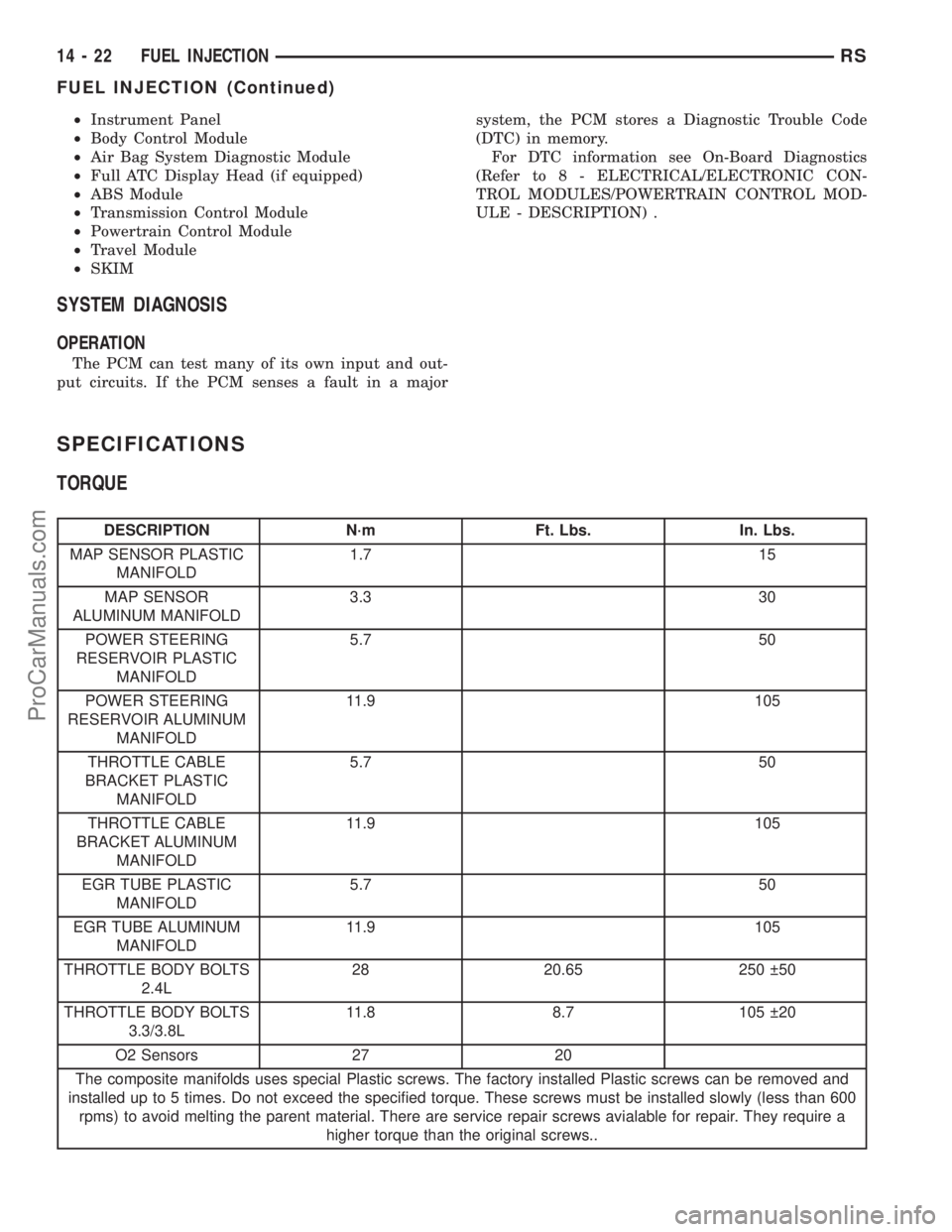
SPECIFICATIONS
TORQUE
DESCRIPTION N´m Ft. Lbs. In. Lbs.
MAP SENSOR PLASTIC
MANIFOLD1.7 15
MAP SENSOR
ALUMINUM MANIFOLD3.3 30
POWER STEERING
RESERVOIR PLASTIC
MANIFOLD5.7 50
POWER STEERING
RESERVOIR ALUMINUM
MANIFOLD11.9 105
THROTTLE CABLE
BRACKET PLASTIC
MANIFOLD5.7 50
THROTTLE CABLE
BRACKET ALUMINUM
MANIFOLD11.9 105
EGR TUBE PLASTIC
MANIFOLD5.7 50
EGR TUBE ALUMINUM
MANIFOLD11.9 105
THROTTLE BODY BOLTS
2.4L28 20.65 250 50
THROTTLE BODY BOLTS
3.3/3.8L11.8 8.7 105 20
O2 Sensors 27 20
The composite manifolds uses special Plastic screws. The factory installed Plastic screws can be removed and
installed up to 5 times. Do not exceed the specified torque. These screws must be installed slowly (less than 600
rpms) to avoid melting the parent material. There are service repair screws avialable for repair. They require a
higher torque than the original screws..
14 - 22 FUEL INJECTIONRS
FUEL INJECTION (Continued)
ProCarManuals.com
Page 1385 of 2177
to the PCM.On V-6 Manual transmission cars (if
equipped) vehicle, the ABS module provides the sig-
nal to the PCM for vehicle speed.
OPERATION
The Transmission Control Module (TCM) supplies
the road speed and distance traveled inputs to the
PCM. From these inputs and the throttle position
sensor input, the PCM determines when a decelera-
tion condition occurs.
FUEL INJECTOR
DESCRIPTION
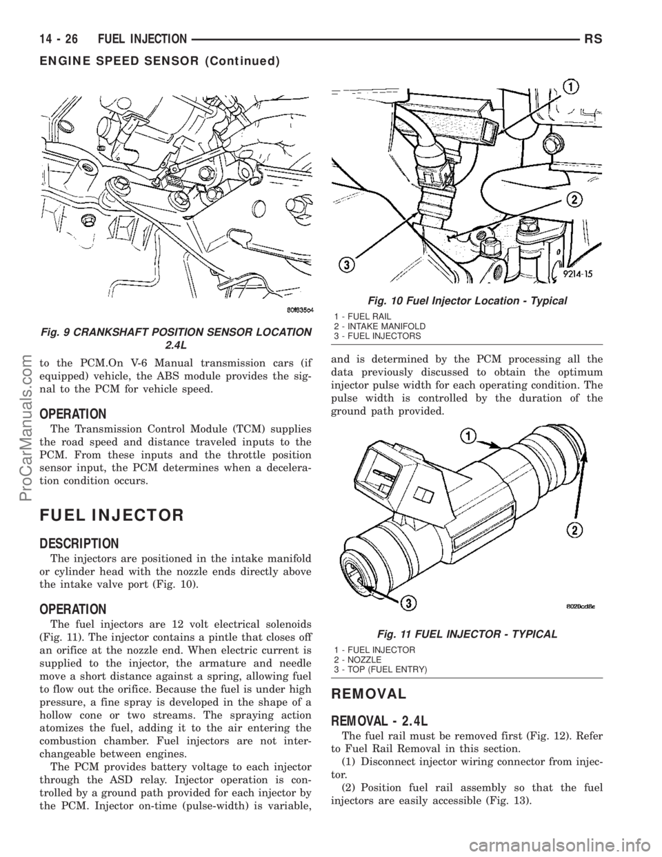
The injectors are positioned in the intake manifold
or cylinder head with the nozzle ends directly above
the intake valve port (Fig. 10).
OPERATION
The fuel injectors are 12 volt electrical solenoids
(Fig. 11). The injector contains a pintle that closes off
an orifice at the nozzle end. When electric current is
supplied to the injector, the armature and needle
move a short distance against a spring, allowing fuel
to flow out the orifice. Because the fuel is under high
pressure, a fine spray is developed in the shape of a
hollow cone or two streams. The spraying action
atomizes the fuel, adding it to the air entering the
combustion chamber. Fuel injectors are not inter-
changeable between engines.
The PCM provides battery voltage to each injector
through the ASD relay. Injector operation is con-
trolled by a ground path provided for each injector by
the PCM. Injector on-time (pulse-width) is variable,and is determined by the PCM processing all the
data previously discussed to obtain the optimum
injector pulse width for each operating condition. The
pulse width is controlled by the duration of the
ground path provided.
REMOVAL
REMOVAL - 2.4L
The fuel rail must be removed first (Fig. 12). Refer
to Fuel Rail Removal in this section.
(1) Disconnect injector wiring connector from injec-
tor.
(2) Position fuel rail assembly so that the fuel
injectors are easily accessible (Fig. 13).
Fig. 9 CRANKSHAFT POSITION SENSOR LOCATION
2.4L
Fig. 10 Fuel Injector Location - Typical
1 - FUEL RAIL
2 - INTAKE MANIFOLD
3 - FUEL INJECTORS
Fig. 11 FUEL INJECTOR - TYPICAL
1 - FUEL INJECTOR
2 - NOZZLE
3 - TOP (FUEL ENTRY)
14 - 26 FUEL INJECTIONRS
ENGINE SPEED SENSOR (Continued)
ProCarManuals.com
Page 1390 of 2177
metric goes down. The first thing that happens as
the key is rolled on, before reaching the crank posi-
tion, the PCM powers up, comes around and looks at
the MAP voltage, and based upon the voltage it sees,
it knows the current barometric pressure relative to
altitude. Once the engine starts, the PCM looks at
the voltage again, continuously every 12 milliseconds,
and compares the current voltage to what it was at
key on. The difference between current and what it
was at key on is manifold vacuum.
During key On (engine not running) the sensor
reads (updates) barometric pressure. A normal range
can be obtained by monitoring known good sensor in
you work area.
As the altitude increases the air becomes thinner
(less oxygen). If a vehicle is started and driven to a
very different altitude than where it was at key On
the barometric pressure needs to be updated. Any
time the PCM sees Wide Open throttle, based upon
TPS angle and RPM it will update barometric pres-
sure in the MAP memory cell. With periodic updates,
the PCM can make its calculations more effectively.
The PCM uses the MAP sensor to aid in calculat-
ing the following:
²Barometric pressure
²Engine load
²Manifold pressure
²Injector pulse-width
²Spark-advance programs
²Shift-point strategies (F4AC1 transmissions
only, via the PCI bus)
²Idle speed
²Decel fuel shutoff
The PCM recognizes a decrease in manifold pres-
sure by monitoring a decrease in voltage from the
reading stored in the barometric pressure memory
cell. The MAP sensor is a linear sensor; as pressure
changes, voltage changes proportionately. The range
of voltage output from the sensor is usually between
4.6 volts at sea level to as low as 0.3 volts at 26 in. of
Hg. Barometric pressure is the pressure exerted by
the atmosphere upon an object. At sea level on a
standard day, no storm, barometric pressure is 29.92
in Hg. For every 100 feet of altitude barometric pres-
sure drops .10 in. Hg. If a storm goes through it can
either add, high pressure, or decrease, low pressure,
from what should be present for that altitude. You
should make a habit of knowing what the average
pressure and corresponding barometric pressure is
for your area.
REMOVAL
REMOVAL - 2.4L
(1) Disconnect the negative battery cable.(2) Disconnect electrical connector and vacuum
hose from MAP sensor (Fig. 20).
(3) Remove two screws holding sensor to the
intake manifold.
REMOVAL - 3.3/3.8L
(1) Disconnect the negative battery cable.
(2) Remove vacuum hose and mounting screws
from manifold absolute pressure (MAP) sensor (Fig.
21).
(3) Disconnect electrical connector from sensor.
Remove sensor.
INSTALLATION
INSTALLATION - 2.4L
(1) Install sensor.
(2) Install two screws and tighten.
(3) Connect the electrical connector and vacuum
hose to the MAP sensor (Fig. 20).
(4) Connect the negative battery cable.
INSTALLATION - 3.3/3.8L
(1) Install sensor (Fig. 21).
(2) Install screws and tighten toPLASTIC MAN-
IFOLD 1.7 N´m (15 in. lbs.) ALUMINUM MANI-
FOLD 3.3 N´m (30 in. lbs.).
(3) Connect the electrical connector to the sensor.
Install vacuum hose.
(4) Connect the negative battery cable.
O2 SENSOR
DESCRIPTION
The upstream oxygen sensor threads into the out-
let flange of the exhaust manifold (Fig. 22) or (Fig.
23).
The downstream heated oxygen sensor threads into
the outlet pipe at the rear of the catalytic convertor
(Fig. 24).
OPERATION
For SBEC vehicles a single sensor ground is used
for all 4 O2 sensors (6 Cyl.). A seperate upstream and
downstream grounds are used on the NGC vehicles
(4 Cyl.).
As vehicles accumulate mileage, the catalytic con-
vertor deteriorates. The deterioration results in a
less efficient catalyst. To monitor catalytic convertor
deterioration, the fuel injection system uses two
heated oxygen sensors. One sensor upstream of the
catalytic convertor, one downstream of the convertor.
The PCM compares the reading from the sensors to
calculate the catalytic convertor oxygen storage
RSFUEL INJECTION14-31
MAP SENSOR (Continued)
ProCarManuals.com
Page 1409 of 2177
(10) Install the coupling onto the intermediate
shaft and install the pinch bolt. Tighten the pinch
bolt to 28 N´m (250 in. lbs.).
(11) Install the cable from the bracket on the col-
umn, then install the pinch side clips.
(12) Reconnect the shift cable at the lever.
(13) Reconnect the wiring harness connectors to
the clockspring, multi-function switch, halo lamp,
SKIM module, ignition switch and BTSI solenoid.
(14) Install the steering wheel (Refer to 19 -
STEERING/COLUMN/STEERING WHEEL -
INSTALLATION).
(15) Install the vibration damper weight.
(16) Install the steering wheel retaining nut.
Tighten the nut to 61 N´m (45 ft. lbs.)
(17) Install the airbag (Refer to 8 - ELECTRICAL/
RESTRAINTS/DRIVER AIRBAG - INSTALLATION).
(18) Install the knee blocker reinforcement (Refer
to 23 - BODY/INSTRUMENT PANEL/KNEE
BLOCKER - INSTALLATION).
(19) Install the parking brake handle link.
(20) Install the knee blocker (Refer to 23 - BODY/
INSTRUMENT PANEL/STEERING COLUMN
OPENING COVER - INSTALLATION).
(21) Install the cluster trim bezel (Refer to 23 -
BODY/INSTRUMENT PANEL/CLUSTER BEZEL -
INSTALLATION).
(22) Install the upper shroud (Refer to 19 -
STEERING/COLUMN/LOWER SHROUD - INSTAL-
LATION).
(23) Install the traction off switch.
(24) Install the lower shroud.
SPECIFICATIONS
COLUMN TORQUE
DESCRIPTION N´mFt.
Lbs.In.
Lbs.
Driver Airbag Attaching Bolts 10 Ð 90
Steering Column Coupling
Pinch Bolt28 Ð 250
Steering Column Mounting
Nuts12 Ð 105
Steering Wheel Retaining
Nut61 45 Ð
IGNITION SWITCH
REMOVAL
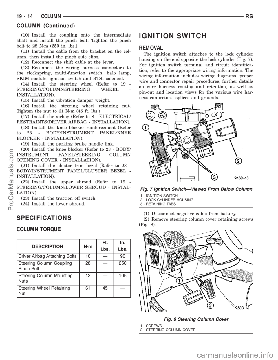
The ignition switch attaches to the lock cylinder
housing on the end opposite the lock cylinder (Fig. 7).
For ignition switch terminal and circuit identifica-
tion, refer to the appropriate wiring information. The
wiring information includes wiring diagrams, proper
wire and connector repair procedures, further details
on wire harness routing and retention, as well as
pin-out and location views for the various wire har-
ness connectors, splices and grounds.
(1) Disconnect negative cable from battery.
(2) Remove steering column cover retaining screws
(Fig. 8).
Fig. 7 Ignition SwitchÐViewed From Below Column
1 - IGNITION SWITCH
2 - LOCK CYLINDER HOUSING
3 - RETAINING TABS
Fig. 8 Steering Column Cover
1 - SCREWS
2 - STEERING COLUMN COVER
19 - 14 COLUMNRS
COLUMN (Continued)
ProCarManuals.com
Page 1411 of 2177
INSTALLATION
The ignition switch attaches to the lock cylinder
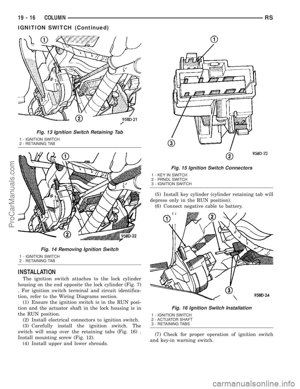
housing on the end opposite the lock cylinder (Fig. 7)
. For ignition switch terminal and circuit identifica-
tion, refer to the Wiring Diagrams section.
(1) Ensure the ignition switch is in the RUN posi-
tion and the actuator shaft in the lock housing is in
the RUN position.
(2) Install electrical connectors to ignition switch.
(3) Carefully install the ignition switch. The
switch will snap over the retaining tabs (Fig. 16) .
Install mounting screw (Fig. 12).
(4) Install upper and lower shrouds.(5) Install key cylinder (cylinder retaining tab will
depress only in the RUN position).
(6) Connect negative cable to battery.
(7) Check for proper operation of ignition switch
and key-in warning switch.
Fig. 13 Ignition Switch Retaining Tab
1 - IGNITION SWITCH
2 - RETAINING TAB
Fig. 14 Removing Ignition Switch
1 - IGNITION SWITCH
2 - RETAINING TAB
Fig. 15 Ignition Switch Connectors
1 - KEY IN SWITCH
2 - PRNDL SWITCH
3 - IGNITION SWITCH
Fig. 16 Ignition Switch Installation
1 - IGNITION SWITCH
2 - ACTUATOR SHAFT
3 - RETAINING TABS
19 - 16 COLUMNRS
IGNITION SWITCH (Continued)
ProCarManuals.com
Page 1412 of 2177
LOCK CYLINDER HOUSING
DESCRIPTION - IGNITION INTERLOCK
All vehicles equipped with automatic transaxles
have an interlock system. The system prevents shift-
ing the vehicle out of Park unless the ignition lock
cylinder is in the Unlock, Run or Start position. In
addition, the operator cannot rotate the key to the
lock position unless the shifter is in the park posi-
tion. On vehicles equipped with floor shift refer to
the - Transaxle for Automatic Transmission Shifter/
Ignition Interlock.
REMOVAL
NOTE: Before proceeding, review all Steering Col-
umn and Airbag Warnings and Cautions. (Refer to
19 - STEERING/COLUMN - WARNING)(Refer to 8 -
ELECTRICAL/RESTRAINTS - WARNING)
(1) Remove battery ground cable terminal from
battery negative post and isolate.
(2) Under instrument panel, remove silencer panel
below lower steering column cover.
(3) Remove screws securing lower steering column
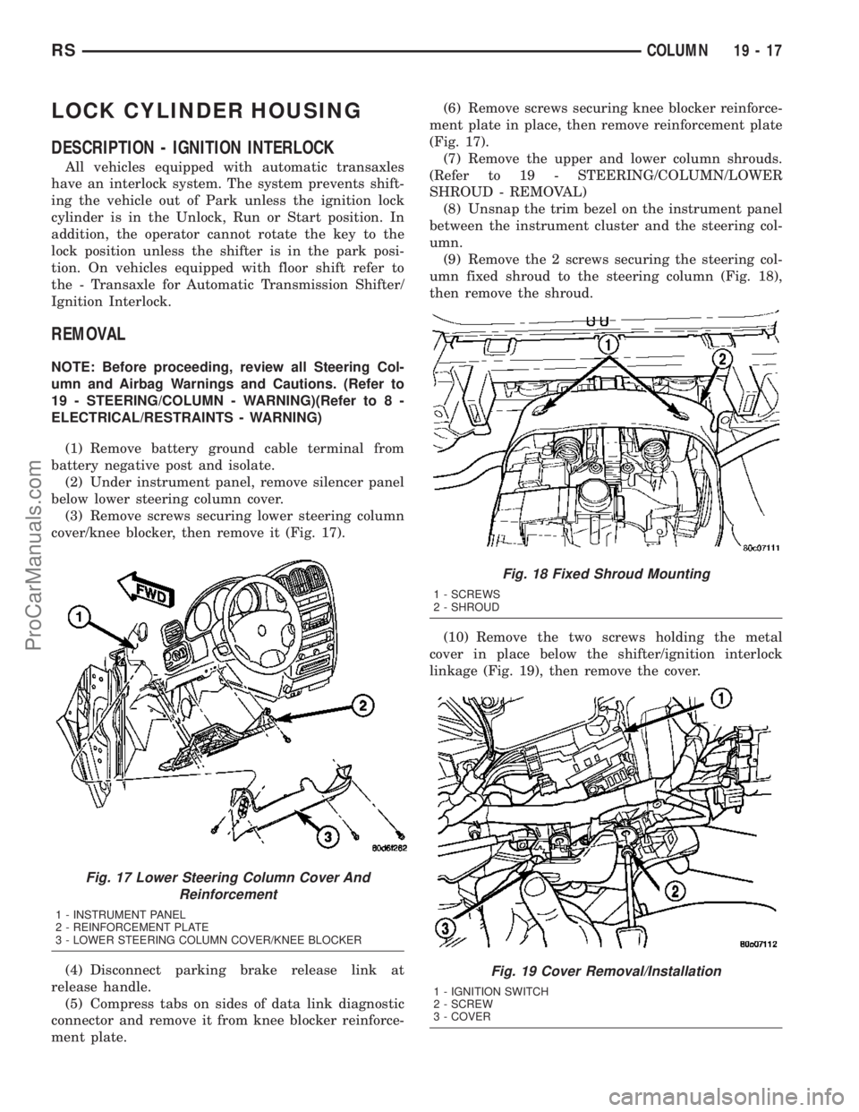
cover/knee blocker, then remove it (Fig. 17).
(4) Disconnect parking brake release link at
release handle.
(5) Compress tabs on sides of data link diagnostic
connector and remove it from knee blocker reinforce-
ment plate.(6) Remove screws securing knee blocker reinforce-
ment plate in place, then remove reinforcement plate
(Fig. 17).
(7) Remove the upper and lower column shrouds.
(Refer to 19 - STEERING/COLUMN/LOWER
SHROUD - REMOVAL)
(8) Unsnap the trim bezel on the instrument panel
between the instrument cluster and the steering col-
umn.
(9) Remove the 2 screws securing the steering col-
umn fixed shroud to the steering column (Fig. 18),
then remove the shroud.
(10) Remove the two screws holding the metal
cover in place below the shifter/ignition interlock
linkage (Fig. 19), then remove the cover.
Fig. 17 Lower Steering Column Cover And
Reinforcement
1 - INSTRUMENT PANEL
2 - REINFORCEMENT PLATE
3 - LOWER STEERING COLUMN COVER/KNEE BLOCKER
Fig. 18 Fixed Shroud Mounting
1 - SCREWS
2 - SHROUD
Fig. 19 Cover Removal/Installation
1 - IGNITION SWITCH
2 - SCREW
3 - COVER
RSCOLUMN19-17
ProCarManuals.com
Page 1413 of 2177
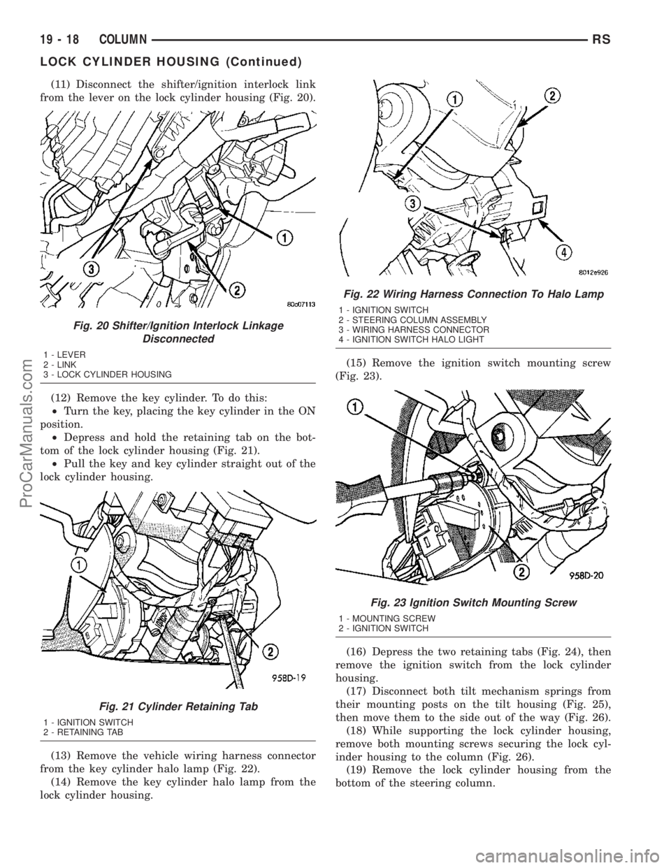
(11) Disconnect the shifter/ignition interlock link
from the lever on the lock cylinder housing (Fig. 20).
(12) Remove the key cylinder. To do this:
²Turn the key, placing the key cylinder in the ON
position.
²Depress and hold the retaining tab on the bot-
tom of the lock cylinder housing (Fig. 21).
²Pull the key and key cylinder straight out of the
lock cylinder housing.
(13) Remove the vehicle wiring harness connector
from the key cylinder halo lamp (Fig. 22).
(14) Remove the key cylinder halo lamp from the
lock cylinder housing.(15) Remove the ignition switch mounting screw
(Fig. 23).
(16) Depress the two retaining tabs (Fig. 24), then
remove the ignition switch from the lock cylinder
housing.
(17) Disconnect both tilt mechanism springs from
their mounting posts on the tilt housing (Fig. 25),
then move them to the side out of the way (Fig. 26).
(18) While supporting the lock cylinder housing,
remove both mounting screws securing the lock cyl-
inder housing to the column (Fig. 26).
(19) Remove the lock cylinder housing from the
bottom of the steering column.
Fig. 20 Shifter/Ignition Interlock Linkage
Disconnected
1 - LEVER
2 - LINK
3 - LOCK CYLINDER HOUSING
Fig. 21 Cylinder Retaining Tab
1 - IGNITION SWITCH
2 - RETAINING TAB
Fig. 22 Wiring Harness Connection To Halo Lamp
1 - IGNITION SWITCH
2 - STEERING COLUMN ASSEMBLY
3 - WIRING HARNESS CONNECTOR
4 - IGNITION SWITCH HALO LIGHT
Fig. 23 Ignition Switch Mounting Screw
1 - MOUNTING SCREW
2 - IGNITION SWITCH
19 - 18 COLUMNRS
LOCK CYLINDER HOUSING (Continued)
ProCarManuals.com
Page 1414 of 2177
INSTALLATION
(1) Install the lock cylinder housing in the bottom
of the steering column lining up the mounting holes.
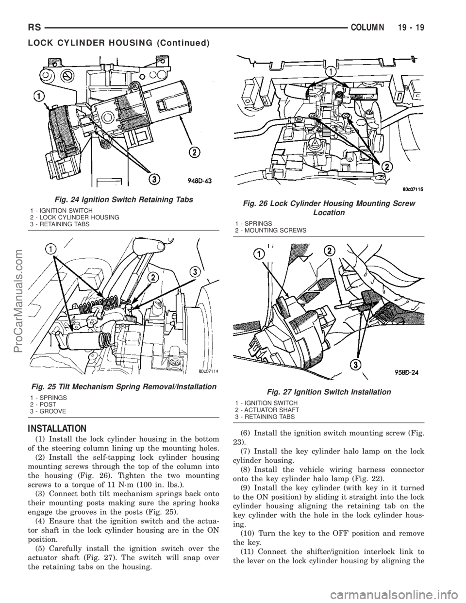
(2) Install the self-tapping lock cylinder housing
mounting screws through the top of the column into
the housing (Fig. 26). Tighten the two mounting
screws to a torque of 11 N´m (100 in. lbs.).
(3) Connect both tilt mechanism springs back onto
their mounting posts making sure the spring hooks
engage the grooves in the posts (Fig. 25).
(4) Ensure that the ignition switch and the actua-
tor shaft in the lock cylinder housing are in the ON
position.
(5) Carefully install the ignition switch over the
actuator shaft (Fig. 27). The switch will snap over
the retaining tabs on the housing.(6) Install the ignition switch mounting screw (Fig.
23).
(7) Install the key cylinder halo lamp on the lock
cylinder housing.
(8) Install the vehicle wiring harness connector
onto the key cylinder halo lamp (Fig. 22).
(9) Install the key cylinder (with key in it turned
to the ON position) by sliding it straight into the lock
cylinder housing aligning the retaining tab on the
key cylinder with the hole in the lock cylinder hous-
ing.
(10) Turn the key to the OFF position and remove
the key.
(11) Connect the shifter/ignition interlock link to
the lever on the lock cylinder housing by aligning the
Fig. 24 Ignition Switch Retaining Tabs
1 - IGNITION SWITCH
2 - LOCK CYLINDER HOUSING
3 - RETAINING TABS
Fig. 25 Tilt Mechanism Spring Removal/Installation
1 - SPRINGS
2 - POST
3 - GROOVE
Fig. 26 Lock Cylinder Housing Mounting Screw
Location
1 - SPRINGS
2 - MOUNTING SCREWS
Fig. 27 Ignition Switch Installation
1 - IGNITION SWITCH
2 - ACTUATOR SHAFT
3 - RETAINING TABS
RSCOLUMN19-19
LOCK CYLINDER HOUSING (Continued)
ProCarManuals.com