2003 CHRYSLER CARAVAN mirror
[x] Cancel search: mirrorPage 1790 of 2177
INSTALLATION
SHORT WHEELBASE
(1) Position the air exhauster to the hole in the
lower aperture panel (Fig. 19).
(2) Using hand pressure, press the air exhauster
into the opening in the lower aperture panel until
the snap features are fully engaged.
(3) Reinstall the rear fascia onto the body. (Refer
to 13 - FRAMES & BUMPERS/BUMPERS/REAR
FASCIA - INSTALLATION).
LONG WHEELBASE
NOTE: Models with the optional rear heater and air
conditioner do not have an air exhauster on the
right side of the vehicle, but have a plastic plug
installed in the right lower aperture panel. This plug
is installed using the same procedure used to
install the air exhauster onto the short wheelbase
model. Refer to SHORT WHEELBASE.
(1) Position the air exhauster to the hole in the
lower aperture panel (Fig. 20).
(2) Using hand pressure, press the air exhauster
into the opening in the lower aperture panel until
the snap features are fully engaged.
(3) Reinstall the quarter trim panel onto the inside
of the left or right quarter inner panel. (Refer to 23 -
BODY/INTERIOR/RIGHT QUARTER TRIM PANEL
- INSTALLATION) or (Refer to 23 - BODY/INTERI-
OR/LEFT QUARTER TRIM PANEL - INSTALLA-
TION).
ROOF JOINT MOLDING
REMOVAL
The RAP molding is set with body side molding
tape. The temperature in the work area and the vehi-
cle should be at least 21É C (70É F) to avoid damag-
ing the RAP moldings.
(1) Warm the affected stick-on molding and body
metal to approximately 38É C (100É F) using a suit-
able heat lamp or heat gun.
(2) Pull stick-on molding from painted surface.
(3) Remove adhesive tape residue from painted
surface of vehicle. Use a 3M Scotch-BriteŸ Molding
Adhesive and Stripe Removal Discs, or equivalent, to
clean adhesive residue from painted surfaces. The
adhesive removal discs are available from automotive
paint suppliers. Refer to instructions supplied with
the discs for proper usage.
INSTALLATION
The RAP molding is set with body side molding
tape. The temperature in the work area and the vehi-
cle should be at least 21É C (70É F) to avoid damag-
ing the RAP moldings.
(1) If molding is to be reused;
(a) Remove tape residue from molding.
(b) Clean back of molding with MopartSuper
Kleen solvent, or equivalent.
(c) Wipe molding dry with lint free cloth.
(d) Apply new body side molding (two sided
adhesive) tape to back of molding.
(2) Clean body surface with MopartSuper Kleen
solvent, or equivalent. Wipe surface dry with lint free
cloth.
(3) Remove protective cover from tape on back of
molding.
(4) Apply molding to body from front of vehicle to
rear.
(5) Using a roller tool, roll molding onto body
panel with enough force to assure adhesion and not
bend roof panels.
SIDE VIEW MIRROR
REMOVAL
(1) Using a trim stick C-4755 or equivalent, lift up
the end of the instrument panel top pad enough to
gain access to the mirror electrical connector, if
equipped. (Refer to 23 - BODY/INSTRUMENT PAN-
EL/INSTRUMENT PANEL TOP COVER -
REMOVAL)
(2) Disconnect the electrical connector, if equipped.
(3) Using a trim stick or equivalent, remove the
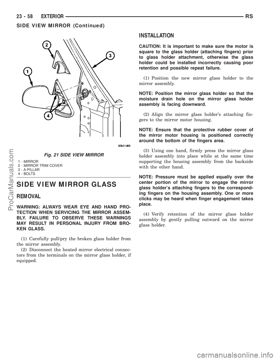
trim cover (Fig. 21).
(4) Remove the bolts.
(5) Remove the mirror from the pillar.
INSTALLATION
(1) Route the mirror wire harness, if equipped,
through the a-pillar and place side view mirror in
position on vehicle (Fig. 21).
(2) Install the bolts and tighten to 10 N´m (85 in.
lbs.).
(3) Install the mirror trim cover.
(4) Connect the electrical connector, if equipped.
(5) Install the instrument panel top cover, if
equipped with the electric mirror. (Refer to 23 -
BODY/INSTRUMENT PANEL/INSTRUMENT
PANEL TOP COVER - INSTALLATION)
RSEXTERIOR23-57
REAR QUARTER PANEL/FENDER AIR EXHAUSTER (Continued)
ProCarManuals.com
Page 1791 of 2177
SIDE VIEW MIRROR GLASS
REMOVAL
WARNING: ALWAYS WEAR EYE AND HAND PRO-
TECTION WHEN SERVICING THE MIRROR ASSEM-
BLY. FAILURE TO OBSERVE THESE WARNINGS
MAY RESULT IN PERSONAL INJURY FROM BRO-
KEN GLASS.
(1) Carefully pull/pry the broken glass holder from
the mirror assembly.
(2) Disconnect the heated mirror electrical connec-
tors from the terminals on the mirror glass holder, if
equipped.
INSTALLATION
CAUTION: It is important to make sure the motor is
square to the glass holder (attaching fingers) prior
to glass holder attachment, otherwise the glass
holder could be installed incorrectly causing poor
retention and possible repeat failure.
(1) Position the new mirror glass holder to the
mirror assembly.
NOTE: Position the mirror glass holder so that the
moisture drain hole on the mirror glass holder
assembly is facing downward.
(2) Align the mirror glass holder's attaching fin-
gers to the mirror motor housing.
NOTE: Ensure that the protective rubber cover of
the mirror motor housing is positioned correctly
around the bottom of the fingers area.
(3) Using one hand, firmly press the mirror glass
holder assembly into place while at the same time
supporting the housing assembly from the backside
with the other hand.
NOTE: Pressure must be applied equally over the
center portion of the mirror to engage the mirror
glass holder's attaching fingers to the correspond-
ing fingers on the housing assembly. One or more
clicks may be heard when finger engagement takes
place.
(4) Verify retention of the mirror glass holder
assembly by gently pulling outward on the mirror
glass holder.
Fig. 21 SIDE VIEW MIRROR
1 - MIRROR
2 - MIRROR TRIM COVER
3 - A-PILLAR
4 - BOLTS
23 - 58 EXTERIORRS
SIDE VIEW MIRROR (Continued)
ProCarManuals.com
Page 1797 of 2177
GLOVE BOX LATCH STRIKER
REMOVAL
(1) Open glove box door.
(2) Remove screws holding lock striker to instru-
ment panel.
(3) Remove glove box latch striker.
INSTALLATION
(1) Install the glove box latch striker.
(2) Install the screws holding latch striker to
instrument panel.
(3) Close glove box door.
INSTRUMENT PANEL
ASSEMBLY
REMOVAL
(1) Disconnect and isolate the battery negative
cable.
(2) Remove the lower console:
(a) Remove six retaining screws.
(b) Pull rearward and disconnect the auxiliary
power outlet.
(c) Remove lower console from vehicle.
(3) Remove the bolts attaching the lower supports
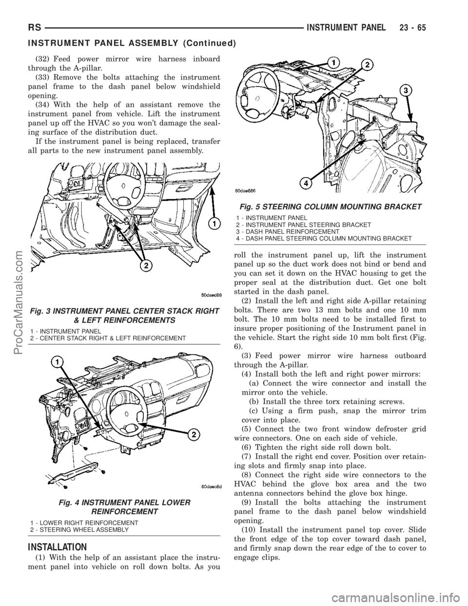
to the instrument panel frame (Fig. 3).
(4) Remove the bolts attaching the lower supports
to the floor pan.
(5) Disconnect the wire connectors from the Pas-
senger Airbag.
(6) Remove the two screws to each right and left
cowl trim covers.
(7) Remove the both left and right side A-pillar
trim covers using a trim stick (special tool #C-4755)
or equivalent gently pry out on the trim covers and
remove.
(8) Remove the glove box:
(a) Push in on sides of glove box bin and lower
door.
(b) Pivot glove box downward and disengage
hinge hooks from instrument panel.
(c) Remove glove box from vehicle.
(9) Disconnect the antenna lead connector from
behind the glove box.
(10) Remove the four screws to the lower steering
column cover.
(11) Remove the eight screws to the steering col-
umn backing plate.
(12) Unclip the Data Link Connector (DLC) from
the steering column backing plate.
(13) Disconnect the left side wiring:
(a) Brake switch.
(b) Main bulkhead connector.(c) Five harness connectors.
(d) Driver airbag connector.
(14) Remove the two screws to the hood release
handle.
(15) Remove five screws to steering column back-
ing plate and remove (Refer to 23 - BODY/INSTRU-
MENT PANEL/KNEE BLOCKER - REMOVAL).
(16) Remove the two steering column shroud
retaining screws. Separate the shrouds and remove
from vehicle.
(17) Remove the screws attaching the instrument
panel reinforcement and remove (Fig. 4).
(18) Disconnect the steering column wiring. There
are seven connectors and then unclip the harness
from the column.
(19) Disconnect the Occupant Restraint Controller
(ORC) harness connector.
(20) Remove the four nuts retaining the steering
column to the dash panel steering column mounting
bracket and lower column to the floor (Fig. 5).
(21) Remove the four nuts attaching the instru-
ment panel to the brake pedal support bracket.
(22) Loosen the left side roll down bolt (Fig. 6).
(23) Remove the left side A-pillar retaining bolts.
There are two 13 mm bolts and one 10 mm bolt.
(24) If equipped with a mechanical transmission
range indicator:
(a) Remove the indicator cable loop.
(b) Remove the clip holding gear shift cable end
to the gear selector adapter.
(c) Pull the cable end from gear selector.
(d) Disconnect the clip for the indicator cable
and guide tube from the shift cable bracket and
move out of the way.
(25) Remove the instrument panel top cover. Using
a trim stick or equivalent, gently pry up on the front
edge of the top cover, pull rearward and remove from
vehicle.
(26) Disconnect the right side wire connectors from
the HVAC behind the glove box area and the two
antenna connectors behind the glove box hinge.
(27) Remove the right end cover by pulling out-
board.
(28) Remove the right side A-pillar retaining bolts.
There are two 13 mm bolts and one 10 mm bolt.
(29) Loosen the right side roll down bolt.
(30) Disconnect the two front window defroster
grid wire connectors. One on each side of vehicle.
(31) Remove both the left and right power mirrors:
(a) Using a trim stick or equivalent, gently pry
out on mirror trim cover.
(b) Open door and remove the three torx retain-
ing screws.
(c) Disconnect the wire connector and remove
mirror from the vehicle.
23 - 64 INSTRUMENT PANELRS
ProCarManuals.com
Page 1798 of 2177
(32) Feed power mirror wire harness inboard
through the A-pillar.
(33) Remove the bolts attaching the instrument
panel frame to the dash panel below windshield
opening.
(34) With the help of an assistant remove the
instrument panel from vehicle. Lift the instrument
panel up off the HVAC so you won't damage the seal-
ing surface of the distribution duct.
If the instrument panel is being replaced, transfer
all parts to the new instrument panel assembly.
INSTALLATION
(1) With the help of an assistant place the instru-
ment panel into vehicle on roll down bolts. As youroll the instrument panel up, lift the instrument
panel up so the duct work does not bind or bend and
you can set it down on the HVAC housing to get the
proper seal at the distribution duct. Get one bolt
started in the dash panel.
(2) Install the left and right side A-pillar retaining
bolts. There are two 13 mm bolts and one 10 mm
bolt. The 10 mm bolts need to be installed first to
insure proper positioning of the Instrument panel in
the vehicle. Start the right side 10 mm bolt first (Fig.
6).
(3) Feed power mirror wire harness outboard
through the A-pillar.
(4) Install both the left and right power mirrors:
(a) Connect the wire connector and install the
mirror onto the vehicle.
(b) Install the three torx retaining screws.
(c) Using a firm push, snap the mirror trim
cover into place.
(5) Connect the two front window defroster grid
wire connectors. One on each side of vehicle.
(6) Tighten the right side roll down bolt.
(7) Install the right end cover. Position over retain-
ing slots and firmly snap into place.
(8) Connect the right side wire connectors to the
HVAC behind the glove box area and the two
antenna connectors behind the glove box hinge.
(9) Install the bolts attaching the instrument
panel frame to the dash panel below windshield
opening.
(10) Install the instrument panel top cover. Slide
the front edge of the top cover toward dash panel,
and firmly snap down the rear edge of the to cover to
engage clips.
Fig. 3 INSTRUMENT PANEL CENTER STACK RIGHT
& LEFT REINFORCEMENTS
1 - INSTRUMENT PANEL
2 - CENTER STACK RIGHT & LEFT REINFORCEMENT
Fig. 4 INSTRUMENT PANEL LOWER
REINFORCEMENT
1 - LOWER RIGHT REINFORCEMENT
2 - STEERING WHEEL ASSEMBLY
Fig. 5 STEERING COLUMN MOUNTING BRACKET
1 - INSTRUMENT PANEL
2 - INSTRUMENT PANEL STEERING BRACKET
3 - DASH PANEL REINFORCEMENT
4 - DASH PANEL STEERING COLUMN MOUNTING BRACKET
RSINSTRUMENT PANEL23-65
INSTRUMENT PANEL ASSEMBLY (Continued)
ProCarManuals.com
Page 1805 of 2177
INTERIOR
TABLE OF CONTENTS
page page
A-PILLAR LOWER EXTENSION TRIM
REMOVAL.............................73
INSTALLATION.........................73
A-PILLAR TRIM
REMOVAL.............................73
INSTALLATION.........................73
ASSIST HANDLE
REMOVAL.............................73
INSTALLATION.........................73
B-PILLAR LOWER TRIM
REMOVAL.............................73
INSTALLATION.........................74
B-PILLAR UPPER TRIM
REMOVAL.............................74
INSTALLATION.........................74
CARPETS AND FLOOR MATS
REMOVAL.............................74
INSTALLATION.........................75
COWL TRIM
REMOVAL.............................75
INSTALLATION.........................75
C-PILLAR TRIM
REMOVAL.............................75
INSTALLATION.........................76
DOOR SILL TRIM PLATE
REMOVAL.............................76
INSTALLATION.........................76
HEADLINER
REMOVAL.............................76
INSTALLATION.........................76
LEFT D-PILLAR TRIM PANEL
REMOVAL.............................77
INSTALLATION.........................77
LIFTGATE SILL PLATE
REMOVAL.............................77
INSTALLATION.........................77
QUARTER TRIM BOLSTER
REMOVAL.............................77INSTALLATION.........................77
RIGHT QUARTER TRIM PANEL
REMOVAL.............................78
INSTALLATION.........................78
LEFT QUARTER TRIM PANEL
REMOVAL.............................78
INSTALLATION.........................78
REAR HEADER TRIM
REMOVAL.............................79
INSTALLATION.........................79
REAR HVAC LOUVER
REMOVAL.............................79
INSTALLATION.........................79
REAR VIEW MIRROR
REMOVAL.............................79
INSTALLATION.........................80
RIGHT D-PILLAR TRIM PANEL
REMOVAL.............................80
INSTALLATION.........................80
SLIDING DOOR SILL PLATE
REMOVAL.............................80
INSTALLATION.........................80
SUN VISOR
REMOVAL.............................81
INSTALLATION.........................81
SUN VISOR SUPPORT
REMOVAL.............................81
INSTALLATION.........................81
FLOOR CONSOLE TRAY
REMOVAL.............................81
INSTALLATION.........................81
FLOOR CONSOLE TRAY - BRACKET
ASSEMBLY
REMOVAL.............................82
INSTALLATION.........................82
23 - 72 INTERIORRS
ProCarManuals.com
Page 1809 of 2177
INSTALLATION
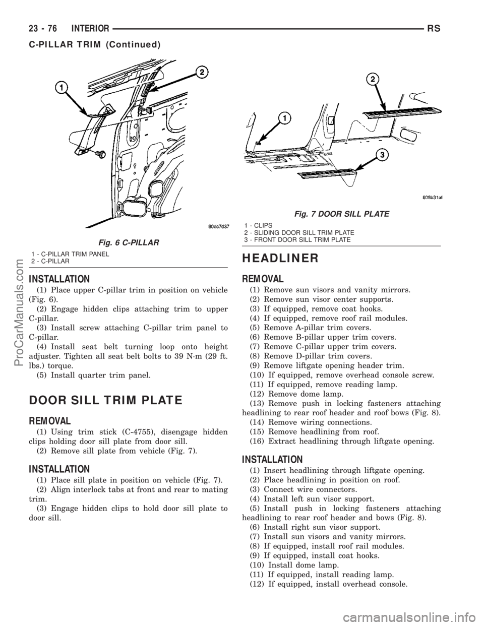
(1) Place upper C-pillar trim in position on vehicle
(Fig. 6).
(2) Engage hidden clips attaching trim to upper
C-pillar.
(3) Install screw attaching C-pillar trim panel to
C-pillar.
(4) Install seat belt turning loop onto height
adjuster. Tighten all seat belt bolts to 39 N´m (29 ft.
lbs.) torque.
(5) Install quarter trim panel.
DOOR SILL TRIM PLATE
REMOVAL
(1) Using trim stick (C-4755), disengage hidden
clips holding door sill plate from door sill.
(2) Remove sill plate from vehicle (Fig. 7).
INSTALLATION
(1) Place sill plate in position on vehicle (Fig. 7).
(2) Align interlock tabs at front and rear to mating
trim.
(3) Engage hidden clips to hold door sill plate to
door sill.
HEADLINER
REMOVAL
(1) Remove sun visors and vanity mirrors.
(2) Remove sun visor center supports.
(3) If equipped, remove coat hooks.
(4) If equipped, remove roof rail modules.
(5) Remove A-pillar trim covers.
(6) Remove B-pillar upper trim covers.
(7) Remove C-pillar upper trim covers.
(8) Remove D-pillar trim covers.
(9) Remove liftgate opening header trim.
(10) If equipped, remove overhead console screw.
(11) If equipped, remove reading lamp.
(12) Remove dome lamp.
(13) Remove push in locking fasteners attaching
headlining to rear roof header and roof bows (Fig. 8).
(14) Remove wiring connections.
(15) Remove headlining from roof.
(16) Extract headlining through liftgate opening.
INSTALLATION
(1) Insert headlining through liftgate opening.
(2) Place headlining in position on roof.
(3) Connect wire connectors.
(4) Install left sun visor support.
(5) Install push in locking fasteners attaching
headlining to rear roof header and bows (Fig. 8).
(6) Install right sun visor support.
(7) Install sun visors and vanity mirrors.
(8) If equipped, install roof rail modules.
(9) If equipped, install coat hooks.
(10) Install dome lamp.
(11) If equipped, install reading lamp.
(12) If equipped, install overhead console.
Fig. 6 C-PILLAR
1 - C-PILLAR TRIM PANEL
2 - C-PILLAR
Fig. 7 DOOR SILL PLATE
1 - CLIPS
2 - SLIDING DOOR SILL TRIM PLATE
3 - FRONT DOOR SILL TRIM PLATE
23 - 76 INTERIORRS
C-PILLAR TRIM (Continued)
ProCarManuals.com
Page 1812 of 2177
(6) Position quarter trim panel on inner quarter
panel.
(7) Install screws attaching rear edge of quarter
trim to attaching bracket or inner quarter panel.
(8) Install screws attaching quarter trim to inner
quarter panel in bolster area.
(9) Install second row seat belts anchor on long
wheel base vehicle. Tighten all seat belt bolts to 39
N´m (28 in. lbs.) torque.
(10) Install first row seat belt anchor.
(11) Install left D-pillar trim panel.
(12) Install C-pillar trim panel.
(13) Install upper left B-pillar trim on three door
vehicle.
(14) Install left quarter trim bolster.
(15) Install front door sill plate on three door vehi-
cle.
(16) Install sliding door sill plate on four door
vehicle.
(17) Install second row seat, if equipped.
(18) Install first row seat.
(19) Connect the battery negative cable.
REAR HEADER TRIM
REMOVAL
(1) Disengage hidden clips holding trim to rear
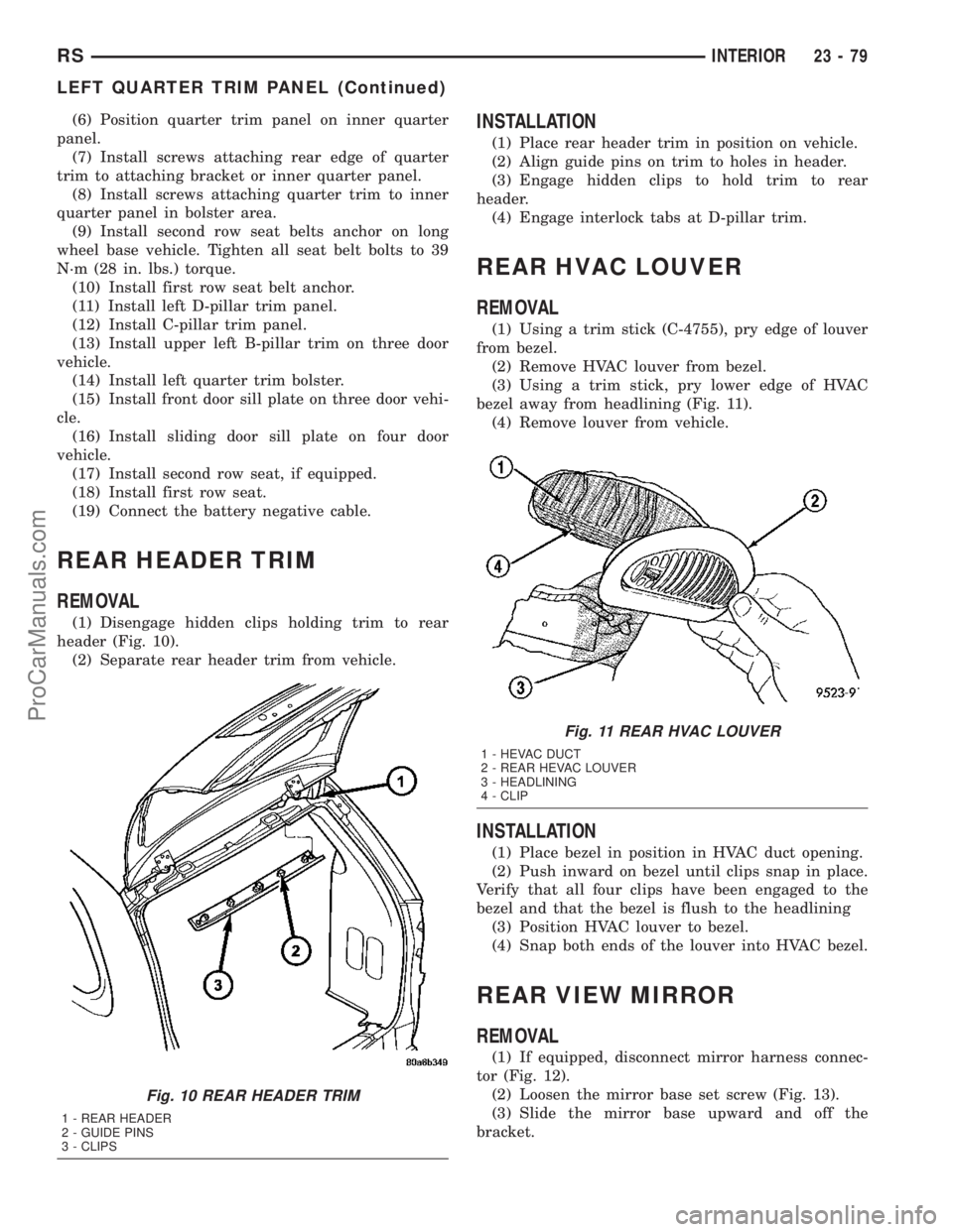
header (Fig. 10).
(2) Separate rear header trim from vehicle.
INSTALLATION
(1) Place rear header trim in position on vehicle.
(2) Align guide pins on trim to holes in header.
(3) Engage hidden clips to hold trim to rear
header.
(4) Engage interlock tabs at D-pillar trim.
REAR HVAC LOUVER
REMOVAL
(1) Using a trim stick (C-4755), pry edge of louver
from bezel.
(2) Remove HVAC louver from bezel.
(3) Using a trim stick, pry lower edge of HVAC
bezel away from headlining (Fig. 11).
(4) Remove louver from vehicle.
INSTALLATION
(1) Place bezel in position in HVAC duct opening.
(2) Push inward on bezel until clips snap in place.
Verify that all four clips have been engaged to the
bezel and that the bezel is flush to the headlining
(3) Position HVAC louver to bezel.
(4) Snap both ends of the louver into HVAC bezel.
REAR VIEW MIRROR
REMOVAL
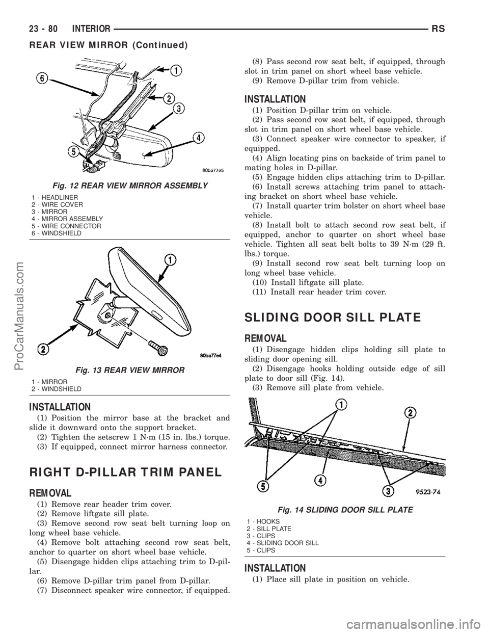
(1) If equipped, disconnect mirror harness connec-
tor (Fig. 12).
(2) Loosen the mirror base set screw (Fig. 13).
(3) Slide the mirror base upward and off the
bracket.
Fig. 10 REAR HEADER TRIM
1 - REAR HEADER
2 - GUIDE PINS
3 - CLIPS
Fig. 11 REAR HVAC LOUVER
1 - HEVAC DUCT
2 - REAR HEVAC LOUVER
3 - HEADLINING
4 - CLIP
RSINTERIOR23-79
LEFT QUARTER TRIM PANEL (Continued)
ProCarManuals.com
Page 1813 of 2177
INSTALLATION
(1) Position the mirror base at the bracket and
slide it downward onto the support bracket.
(2) Tighten the setscrew 1 N´m (15 in. lbs.) torque.
(3) If equipped, connect mirror harness connector.
RIGHT D-PILLAR TRIM PANEL
REMOVAL
(1) Remove rear header trim cover.
(2) Remove liftgate sill plate.
(3) Remove second row seat belt turning loop on
long wheel base vehicle.
(4) Remove bolt attaching second row seat belt,
anchor to quarter on short wheel base vehicle.
(5) Disengage hidden clips attaching trim to D-pil-
lar.
(6) Remove D-pillar trim panel from D-pillar.
(7) Disconnect speaker wire connector, if equipped.(8) Pass second row seat belt, if equipped, through
slot in trim panel on short wheel base vehicle.
(9) Remove D-pillar trim from vehicle.
INSTALLATION
(1) Position D-pillar trim on vehicle.
(2) Pass second row seat belt, if equipped, through
slot in trim panel on short wheel base vehicle.
(3) Connect speaker wire connector to speaker, if
equipped.
(4) Align locating pins on backside of trim panel to
mating holes in D-pillar.
(5) Engage hidden clips attaching trim to D-pillar.
(6) Install screws attaching trim panel to attach-
ing bracket on short wheel base vehicle.
(7) Install quarter trim bolster on short wheel base
vehicle.
(8) Install bolt to attach second row seat belt, if
equipped, anchor to quarter on short wheel base
vehicle. Tighten all seat belt bolts to 39 N´m (29 ft.
lbs.) torque.
(9) Install second row seat belt turning loop on
long wheel base vehicle.
(10) Install liftgate sill plate.
(11) Install rear header trim cover.
SLIDING DOOR SILL PLATE
REMOVAL
(1) Disengage hidden clips holding sill plate to
sliding door opening sill.
(2) Disengage hooks holding outside edge of sill
plate to door sill (Fig. 14).
(3) Remove sill plate from vehicle.
INSTALLATION
(1) Place sill plate in position on vehicle.
Fig. 12 REAR VIEW MIRROR ASSEMBLY
1 - HEADLINER
2 - WIRE COVER
3 - MIRROR
4 - MIRROR ASSEMBLY
5 - WIRE CONNECTOR
6 - WINDSHIELD
Fig. 13 REAR VIEW MIRROR
1 - MIRROR
2 - WINDSHIELD
Fig. 14 SLIDING DOOR SILL PLATE
1 - HOOKS
2 - SILL PLATE
3 - CLIPS
4 - SLIDING DOOR SILL
5 - CLIPS
23 - 80 INTERIORRS
REAR VIEW MIRROR (Continued)
ProCarManuals.com