2003 CHRYSLER CARAVAN mirror
[x] Cancel search: mirrorPage 1123 of 2177
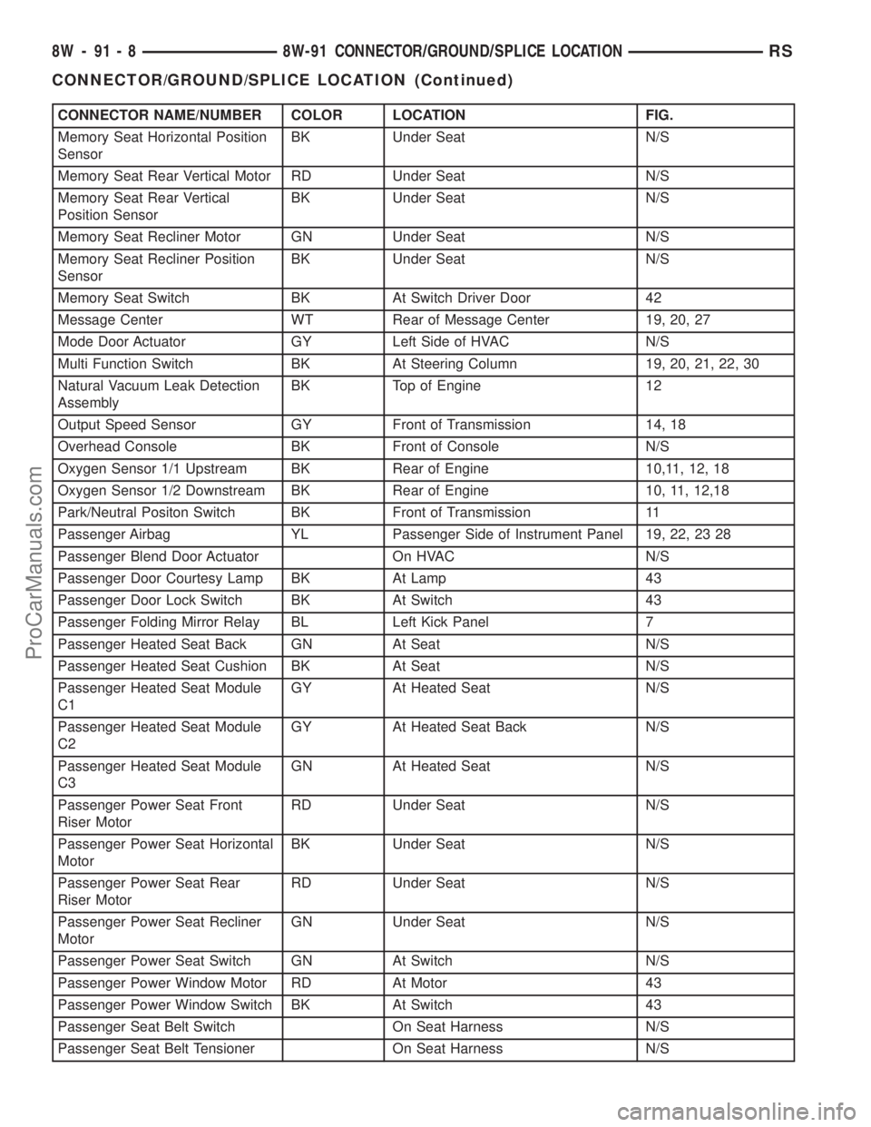
CONNECTOR NAME/NUMBER COLOR LOCATION FIG.
Memory Seat Horizontal Position
SensorBK Under Seat N/S
Memory Seat Rear Vertical Motor RD Under Seat N/S
Memory Seat Rear Vertical
Position SensorBK Under Seat N/S
Memory Seat Recliner Motor GN Under Seat N/S
Memory Seat Recliner Position
SensorBK Under Seat N/S
Memory Seat Switch BK At Switch Driver Door 42
Message Center WT Rear of Message Center 19, 20, 27
Mode Door Actuator GY Left Side of HVAC N/S
Multi Function Switch BK At Steering Column 19, 20, 21, 22, 30
Natural Vacuum Leak Detection
AssemblyBK Top of Engine 12
Output Speed Sensor GY Front of Transmission 14, 18
Overhead Console BK Front of Console N/S
Oxygen Sensor 1/1 Upstream BK Rear of Engine 10,11, 12, 18
Oxygen Sensor 1/2 Downstream BK Rear of Engine 10, 11, 12,18
Park/Neutral Positon Switch BK Front of Transmission 11
Passenger Airbag YL Passenger Side of Instrument Panel 19, 22, 23 28
Passenger Blend Door Actuator On HVAC N/S
Passenger Door Courtesy Lamp BK At Lamp 43
Passenger Door Lock Switch BK At Switch 43
Passenger Folding Mirror Relay BL Left Kick Panel 7
Passenger Heated Seat Back GN At Seat N/S
Passenger Heated Seat Cushion BK At Seat N/S
Passenger Heated Seat Module
C1GY At Heated Seat N/S
Passenger Heated Seat Module
C2GY At Heated Seat Back N/S
Passenger Heated Seat Module
C3GN At Heated Seat N/S
Passenger Power Seat Front
Riser MotorRD Under Seat N/S
Passenger Power Seat Horizontal
MotorBK Under Seat N/S
Passenger Power Seat Rear
Riser MotorRD Under Seat N/S
Passenger Power Seat Recliner
MotorGN Under Seat N/S
Passenger Power Seat Switch GN At Switch N/S
Passenger Power Window Motor RD At Motor 43
Passenger Power Window Switch BK At Switch 43
Passenger Seat Belt Switch On Seat Harness N/S
Passenger Seat Belt Tensioner On Seat Harness N/S
8W - 91 - 8 8W-91 CONNECTOR/GROUND/SPLICE LOCATIONRS
CONNECTOR/GROUND/SPLICE LOCATION (Continued)
ProCarManuals.com
Page 1124 of 2177
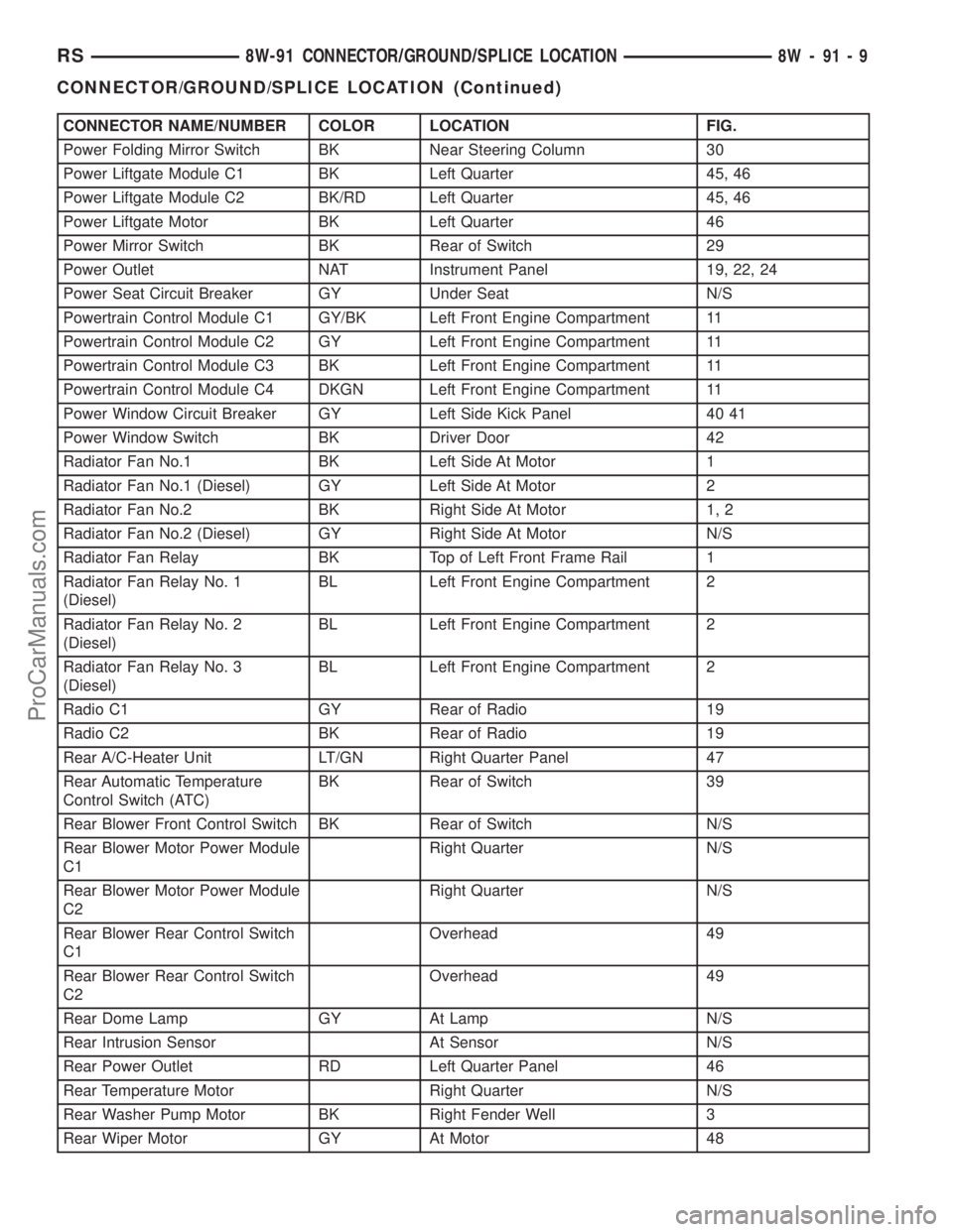
CONNECTOR NAME/NUMBER COLOR LOCATION FIG.
Power Folding Mirror Switch BK Near Steering Column 30
Power Liftgate Module C1 BK Left Quarter 45, 46
Power Liftgate Module C2 BK/RD Left Quarter 45, 46
Power Liftgate Motor BK Left Quarter 46
Power Mirror Switch BK Rear of Switch 29
Power Outlet NAT Instrument Panel 19, 22, 24
Power Seat Circuit Breaker GY Under Seat N/S
Powertrain Control Module C1 GY/BK Left Front Engine Compartment 11
Powertrain Control Module C2 GY Left Front Engine Compartment 11
Powertrain Control Module C3 BK Left Front Engine Compartment 11
Powertrain Control Module C4 DKGN Left Front Engine Compartment 11
Power Window Circuit Breaker GY Left Side Kick Panel 40 41
Power Window Switch BK Driver Door 42
Radiator Fan No.1 BK Left Side At Motor 1
Radiator Fan No.1 (Diesel) GY Left Side At Motor 2
Radiator Fan No.2 BK Right Side At Motor 1, 2
Radiator Fan No.2 (Diesel) GY Right Side At Motor N/S
Radiator Fan Relay BK Top of Left Front Frame Rail 1
Radiator Fan Relay No. 1
(Diesel)BL Left Front Engine Compartment 2
Radiator Fan Relay No. 2
(Diesel)BL Left Front Engine Compartment 2
Radiator Fan Relay No. 3
(Diesel)BL Left Front Engine Compartment 2
Radio C1 GY Rear of Radio 19
Radio C2 BK Rear of Radio 19
Rear A/C-Heater Unit LT/GN Right Quarter Panel 47
Rear Automatic Temperature
Control Switch (ATC)BK Rear of Switch 39
Rear Blower Front Control Switch BK Rear of Switch N/S
Rear Blower Motor Power Module
C1Right Quarter N/S
Rear Blower Motor Power Module
C2Right Quarter N/S
Rear Blower Rear Control Switch
C1Overhead 49
Rear Blower Rear Control Switch
C2Overhead 49
Rear Dome Lamp GY At Lamp N/S
Rear Intrusion Sensor At Sensor N/S
Rear Power Outlet RD Left Quarter Panel 46
Rear Temperature Motor Right Quarter N/S
Rear Washer Pump Motor BK Right Fender Well 3
Rear Wiper Motor GY At Motor 48
RS8W-91 CONNECTOR/GROUND/SPLICE LOCATION8W-91-9
CONNECTOR/GROUND/SPLICE LOCATION (Continued)
ProCarManuals.com
Page 1125 of 2177
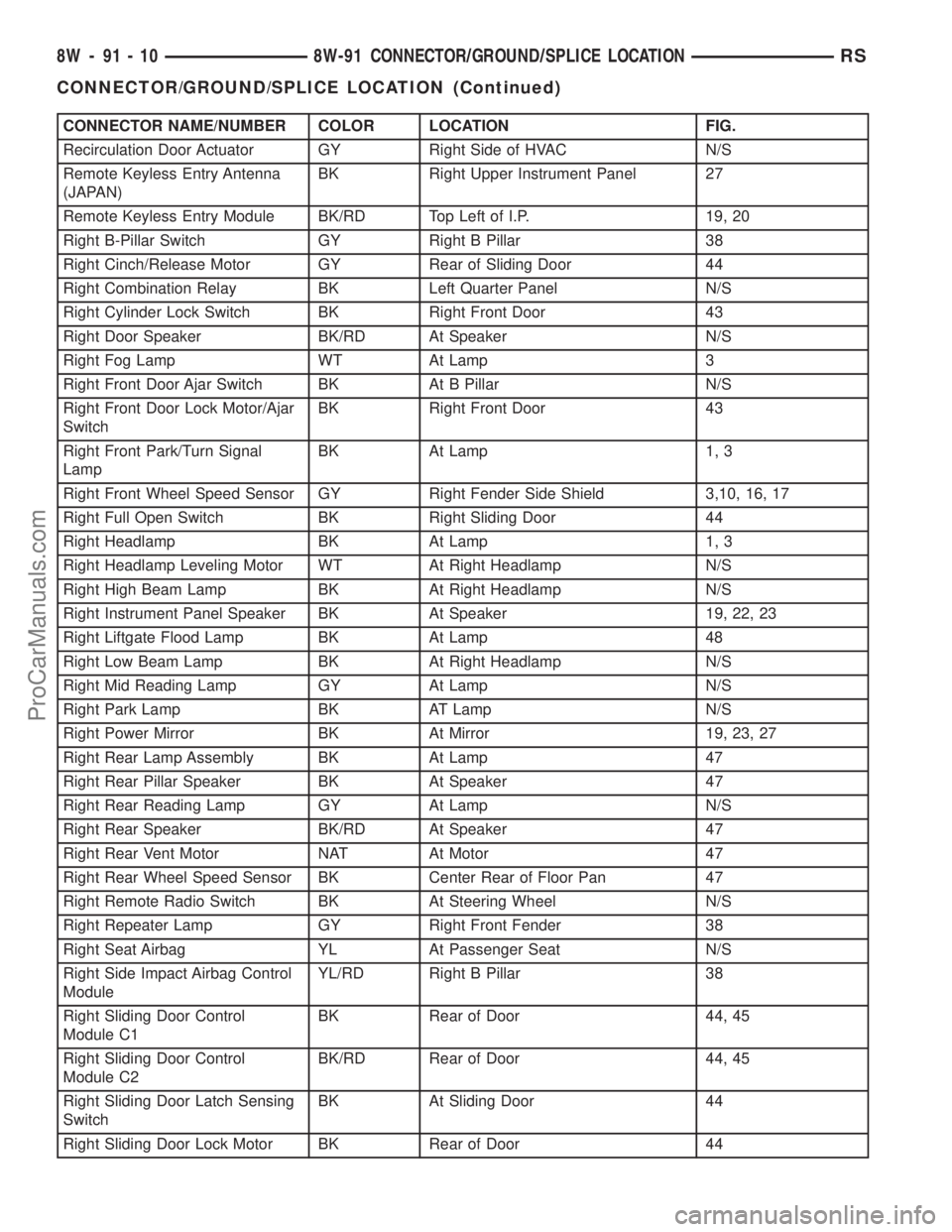
CONNECTOR NAME/NUMBER COLOR LOCATION FIG.
Recirculation Door Actuator GY Right Side of HVAC N/S
Remote Keyless Entry Antenna
(JAPAN)BK Right Upper Instrument Panel 27
Remote Keyless Entry Module BK/RD Top Left of I.P. 19, 20
Right B-Pillar Switch GY Right B Pillar 38
Right Cinch/Release Motor GY Rear of Sliding Door 44
Right Combination Relay BK Left Quarter Panel N/S
Right Cylinder Lock Switch BK Right Front Door 43
Right Door Speaker BK/RD At Speaker N/S
Right Fog Lamp WT At Lamp 3
Right Front Door Ajar Switch BK At B Pillar N/S
Right Front Door Lock Motor/Ajar
SwitchBK Right Front Door 43
Right Front Park/Turn Signal
LampBK At Lamp 1, 3
Right Front Wheel Speed Sensor GY Right Fender Side Shield 3,10, 16, 17
Right Full Open Switch BK Right Sliding Door 44
Right Headlamp BK At Lamp 1, 3
Right Headlamp Leveling Motor WT At Right Headlamp N/S
Right High Beam Lamp BK At Right Headlamp N/S
Right Instrument Panel Speaker BK At Speaker 19, 22, 23
Right Liftgate Flood Lamp BK At Lamp 48
Right Low Beam Lamp BK At Right Headlamp N/S
Right Mid Reading Lamp GY At Lamp N/S
Right Park Lamp BK AT Lamp N/S
Right Power Mirror BK At Mirror 19, 23, 27
Right Rear Lamp Assembly BK At Lamp 47
Right Rear Pillar Speaker BK At Speaker 47
Right Rear Reading Lamp GY At Lamp N/S
Right Rear Speaker BK/RD At Speaker 47
Right Rear Vent Motor NAT At Motor 47
Right Rear Wheel Speed Sensor BK Center Rear of Floor Pan 47
Right Remote Radio Switch BK At Steering Wheel N/S
Right Repeater Lamp GY Right Front Fender 38
Right Seat Airbag YL At Passenger Seat N/S
Right Side Impact Airbag Control
ModuleYL/RD Right B Pillar 38
Right Sliding Door Control
Module C1BK Rear of Door 44, 45
Right Sliding Door Control
Module C2BK/RD Rear of Door 44, 45
Right Sliding Door Latch Sensing
SwitchBK At Sliding Door 44
Right Sliding Door Lock Motor BK Rear of Door 44
8W - 91 - 10 8W-91 CONNECTOR/GROUND/SPLICE LOCATIONRS
CONNECTOR/GROUND/SPLICE LOCATION (Continued)
ProCarManuals.com
Page 1129 of 2177
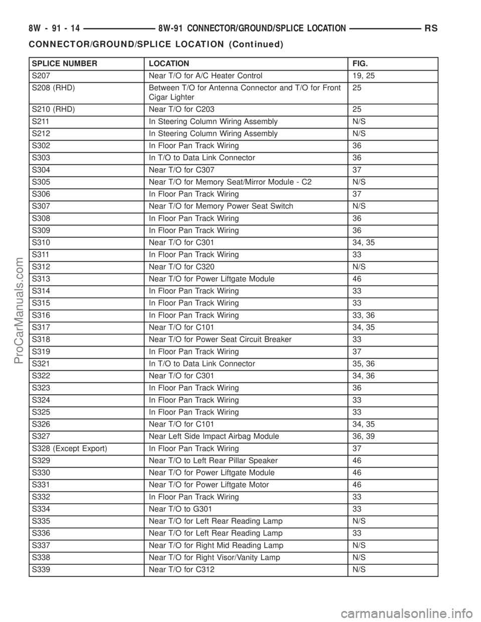
SPLICE NUMBER LOCATION FIG.
S207 Near T/O for A/C Heater Control 19, 25
S208 (RHD) Between T/O for Antenna Connector and T/O for Front
Cigar Lighter25
S210 (RHD) Near T/O for C203 25
S211 In Steering Column Wiring Assembly N/S
S212 In Steering Column Wiring Assembly N/S
S302 In Floor Pan Track Wiring 36
S303 In T/O to Data Link Connector 36
S304 Near T/O for C307 37
S305 Near T/O for Memory Seat/Mirror Module - C2 N/S
S306 In Floor Pan Track Wiring 37
S307 Near T/O for Memory Power Seat Switch N/S
S308 In Floor Pan Track Wiring 36
S309 In Floor Pan Track Wiring 36
S310 Near T/O for C301 34, 35
S311 In Floor Pan Track Wiring 33
S312 Near T/O for C320 N/S
S313 Near T/O for Power Liftgate Module 46
S314 In Floor Pan Track Wiring 33
S315 In Floor Pan Track Wiring 33
S316 In Floor Pan Track Wiring 33, 36
S317 Near T/O for C101 34, 35
S318 Near T/O for Power Seat Circuit Breaker 33
S319 In Floor Pan Track Wiring 37
S321 In T/O to Data Link Connector 35, 36
S322 Near T/O for C301 34, 36
S323 In Floor Pan Track Wiring 36
S324 In Floor Pan Track Wiring 33
S325 In Floor Pan Track Wiring 33
S326 Near T/O for C101 34, 35
S327 Near Left Side Impact Airbag Module 36, 39
S328 (Except Export) In Floor Pan Track Wiring 37
S329 Near T/O to Left Rear Pillar Speaker 46
S330 Near T/O for Power Liftgate Module 46
S331 Near T/O for Power Liftgate Motor 46
S332 In Floor Pan Track Wiring 33
S334 Near T/O to G301 33
S335 Near T/O for Left Rear Reading Lamp N/S
S336 Near T/O for Left Rear Reading Lamp 33
S337 Near T/O for Right Mid Reading Lamp N/S
S338 Near T/O for Right Visor/Vanity Lamp N/S
S339 Near T/O for C312 N/S
8W - 91 - 14 8W-91 CONNECTOR/GROUND/SPLICE LOCATIONRS
CONNECTOR/GROUND/SPLICE LOCATION (Continued)
ProCarManuals.com
Page 1418 of 2177
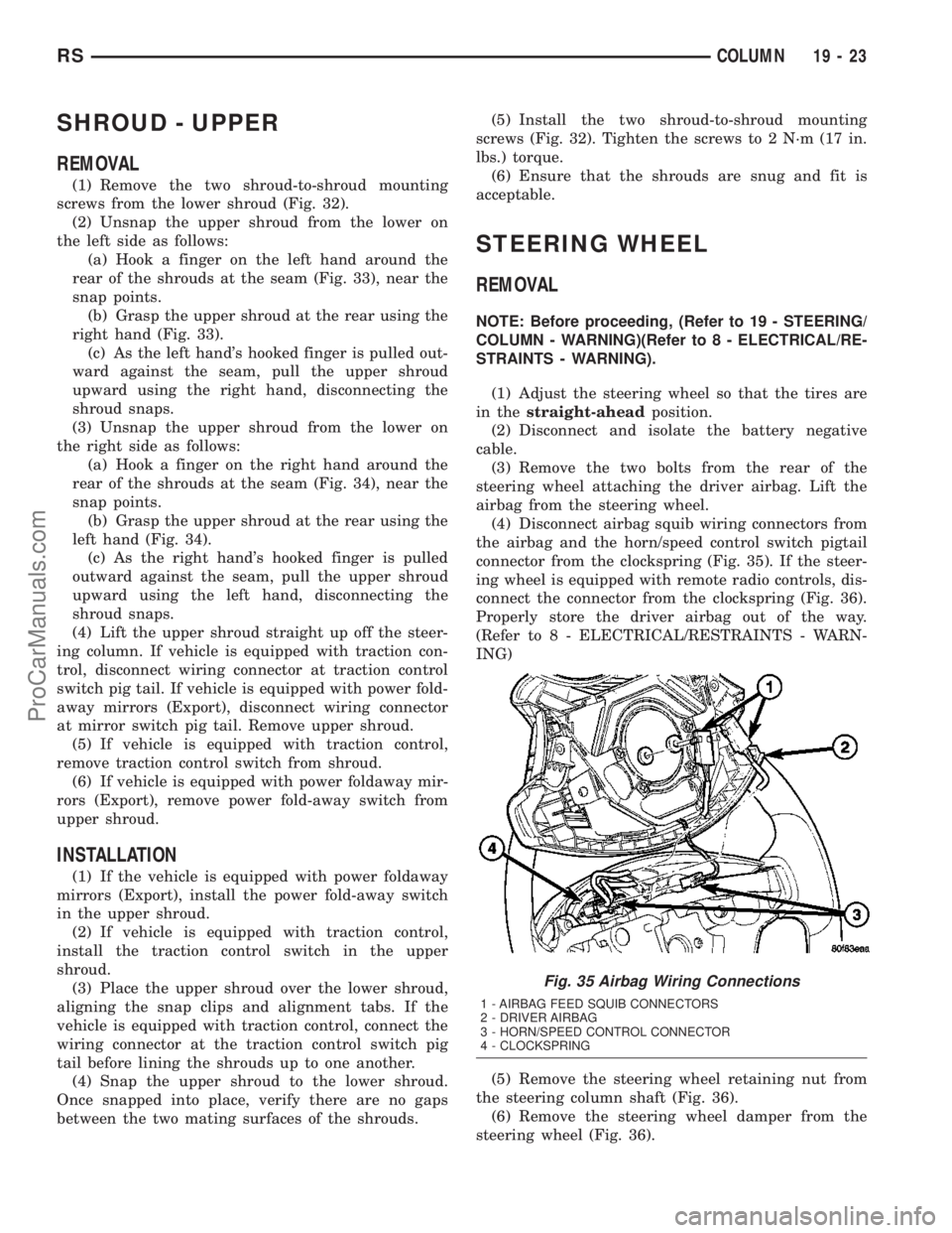
SHROUD - UPPER
REMOVAL
(1) Remove the two shroud-to-shroud mounting
screws from the lower shroud (Fig. 32).
(2) Unsnap the upper shroud from the lower on
the left side as follows:
(a) Hook a finger on the left hand around the
rear of the shrouds at the seam (Fig. 33), near the
snap points.
(b) Grasp the upper shroud at the rear using the
right hand (Fig. 33).
(c) As the left hand's hooked finger is pulled out-
ward against the seam, pull the upper shroud
upward using the right hand, disconnecting the
shroud snaps.
(3) Unsnap the upper shroud from the lower on
the right side as follows:
(a) Hook a finger on the right hand around the
rear of the shrouds at the seam (Fig. 34), near the
snap points.
(b) Grasp the upper shroud at the rear using the
left hand (Fig. 34).
(c) As the right hand's hooked finger is pulled
outward against the seam, pull the upper shroud
upward using the left hand, disconnecting the
shroud snaps.
(4) Lift the upper shroud straight up off the steer-
ing column. If vehicle is equipped with traction con-
trol, disconnect wiring connector at traction control
switch pig tail. If vehicle is equipped with power fold-
away mirrors (Export), disconnect wiring connector
at mirror switch pig tail. Remove upper shroud.
(5) If vehicle is equipped with traction control,
remove traction control switch from shroud.
(6) If vehicle is equipped with power foldaway mir-
rors (Export), remove power fold-away switch from
upper shroud.
INSTALLATION
(1) If the vehicle is equipped with power foldaway
mirrors (Export), install the power fold-away switch
in the upper shroud.
(2) If vehicle is equipped with traction control,
install the traction control switch in the upper
shroud.
(3) Place the upper shroud over the lower shroud,
aligning the snap clips and alignment tabs. If the
vehicle is equipped with traction control, connect the
wiring connector at the traction control switch pig
tail before lining the shrouds up to one another.
(4) Snap the upper shroud to the lower shroud.
Once snapped into place, verify there are no gaps
between the two mating surfaces of the shrouds.(5) Install the two shroud-to-shroud mounting
screws (Fig. 32). Tighten the screws to 2 N´m (17 in.
lbs.) torque.
(6) Ensure that the shrouds are snug and fit is
acceptable.
STEERING WHEEL
REMOVAL
NOTE: Before proceeding, (Refer to 19 - STEERING/
COLUMN - WARNING)(Refer to 8 - ELECTRICAL/RE-
STRAINTS - WARNING).
(1) Adjust the steering wheel so that the tires are
in thestraight-aheadposition.
(2) Disconnect and isolate the battery negative
cable.
(3) Remove the two bolts from the rear of the
steering wheel attaching the driver airbag. Lift the
airbag from the steering wheel.
(4) Disconnect airbag squib wiring connectors from
the airbag and the horn/speed control switch pigtail
connector from the clockspring (Fig. 35). If the steer-
ing wheel is equipped with remote radio controls, dis-
connect the connector from the clockspring (Fig. 36).
Properly store the driver airbag out of the way.
(Refer to 8 - ELECTRICAL/RESTRAINTS - WARN-
ING)
(5) Remove the steering wheel retaining nut from
the steering column shaft (Fig. 36).
(6) Remove the steering wheel damper from the
steering wheel (Fig. 36).
Fig. 35 Airbag Wiring Connections
1 - AIRBAG FEED SQUIB CONNECTORS
2 - DRIVER AIRBAG
3 - HORN/SPEED CONTROL CONNECTOR
4 - CLOCKSPRING
RSCOLUMN19-23
ProCarManuals.com
Page 1735 of 2177
DIAGNOSIS AND TESTING
DIAGNOSIS AND TESTING - WATER LEAKS
Water leaks can be caused by poor sealing,
improper body component alignment, body seam
porosity, missing plugs, or blocked drain holes. Cen-
trifugal and gravitational force can cause water to
drip from a location away from the actual leak point,
making leak detection difficult. All body sealing
points should be water tight in normal wet-driving
conditions. Water flowing downward from the front of
the vehicle should not enter the passenger or luggage
compartment. Moving sealing surfaces will not
always seal water tight under all conditions. At
times, side glass or door seals will allow water to
enter the passenger compartment during high pres-
sure washing or hard driving rain (severe) condi-
tions. Overcompensating on door or glass
adjustments to stop a water leak that occurs under
severe conditions can cause premature seal wear and
excessive closing or latching effort. After completing
a repair, water test vehicle to verify leak has stopped
before returning vehicle to use.
VISUAL INSPECTION BEFORE WATER LEAK TESTS
Verify that floor and body plugs are in place, body
drains are clear, and body components are properly
aligned and sealed. If component alignment or seal-
ing is necessary, refer to the appropriate section of
this group for proper procedures.
WATER LEAK TESTS
WARNING: DO NOT USE ELECTRIC SHOP LIGHTS
OR TOOLS IN WATER TEST AREA. PERSONAL
INJURY CAN RESULT.
When the conditions causing a water leak have
been determined, simulate the conditions as closely
as possible.
²If a leak occurs with the vehicle parked in a
steady light rain, flood the leak area with an open-
ended garden hose.
²If a leak occurs while driving at highway speeds
in a steady rain, test the leak area with a reasonable
velocity stream or fan spray of water. Direct the
spray in a direction comparable to actual conditions.
²If a leak occurs when the vehicle is parked on an
incline, hoist the end or side of the vehicle to simu-
late this condition. This method can be used when
the leak occurs when the vehicle accelerates, stops or
turns. If the leak occurs on acceleration, hoist the
front of the vehicle. If the leak occurs when braking,
hoist the back of the vehicle. If the leak occurs on left
turns, hoist the left side of the vehicle. If the leak
occurs on right turns, hoist the right side of the vehi-cle. For hoisting recommendations (Refer to LUBRI-
CATION & MAINTENANCE/HOISTING -
STANDARD PROCEDURE).
WATER LEAK DETECTION
To detect a water leak point-of-entry, do a water
test and watch for water tracks or droplets forming
on the inside of the vehicle. If necessary, remove inte-
rior trim covers or panels to gain visual access to the
leak area. If the hose cannot be positioned without
being held, have someone help do the water test.
Some water leaks must be tested for a considerable
length of time to become apparent. When a leak
appears, find the highest point of the water track or
drop. The highest point usually will show the point of
entry. After leak point has been found, repair the
leak and water test to verify that the leak has
stopped.
Locating the entry point of water that is leaking
into a cavity between panels can be difficult. The
trapped water may splash or run from the cavity,
often at a distance from the entry point. Most water
leaks of this type become apparent after accelerating,
stopping, turning, or when on an incline.
MIRROR INSPECTION METHOD
When a leak point area is visually obstructed, use
a suitable mirror to gain visual access. A mirror can
also be used to deflect light to a limited-access area
to assist in locating a leak point.
BRIGHT LIGHT LEAK TEST METHOD
Some water leaks in the luggage compartment can
be detected without water testing. Position the vehicle
in a brightly lit area. From inside the darkened lug-
gage compartment inspect around seals and body
seams. If necessary, have a helper direct a drop light
over the suspected leak areas around the luggage com-
partment. If light is visible through a normally sealed
location, water could enter through the opening.
PRESSURIZED LEAK TEST METHOD
When a water leak into the passenger compart-
ment cannot be detected by water testing, pressurize
the passenger compartment and soap test exterior of
the vehicle. To pressurize the passenger compart-
ment, close all doors and windows, start engine, and
set heater control to high blower in HEAT position. If
engine can not be started, connect a charger to the
battery to ensure adequate voltage to the blower.
With interior pressurized, apply dish detergent solu-
tion to suspected leak area on the exterior of the
vehicle. Apply detergent solution with spray device or
soft bristle brush. If soap bubbles occur at a body
seam, joint, seal or gasket, the leak entry point could
be at that location.
23 - 2 BODYRS
BODY (Continued)
ProCarManuals.com
Page 1745 of 2177
DESCRIPTION N´m Ft. Lbs. In. Lbs.
Luggage rack crossbar fasteners 4 Ð 35
Lumbar support handle screw 1 Ð 9
Pivot bolt to the body half of hood hinge 28 21 Ð
Prop assembly to lifgate bolts 28 21 Ð
Rear door glass to regulator bolt 11 8 Ð
Rear door hinge to B-pillar bolt 28 20 Ð
Rear door hinge to door bolt 28 20 Ð
Rear door latch striker 28 20 Ð
Rear latch to sliding door end frame 28 20 Ð
Rear seat back to seat cushion bolt 27 19 Ð
Recliner to seat back frame 12 9 Ð
Seatback frame upper rail 8 Ð 71
Seatback hinge bolt 48 35 Ð
Seatback hinge cover screws 2.3 Ð 20
Shoulder belt turning loop onto height adjuster 39 29 Ð
Side view mirror bolts 10 Ð 85
Sliding door center hinge adjusting bolt 15 Ð 130
Sliding door glass nuts 3.4 Ð 30
Sliding door latch striker 28 21 Ð
Sliding door to roller arm bracket 12 9 Ð
Storage bin track guide to seat riser 3.5 Ð 31
Sunroof opening panel to lifter arm screws 5 44
Sunroof opening panel motor screws 4 35
Sunroof trough bracket to roof bolts 6 53
Sunroof trough to trough bracket bolts 6 53
Sunroof trough bracket bolts 6 53
Support cylinders to liftgate 28 21 Ð
BODY LUBRICATION
LUBRICATION REQUIREMENTS
Body mechanisms and linkages should be
inspected, cleaned, and lubricated, as required, to
maintain ease of operation and to provide protection
against rust and wear. When performing other under
hood services, the hood latch release mechanism and
safety catch should be inspected, cleaned, and lubri-
cated. During the winter season, external door lock
cylinders should be lubricated to assure proper oper-
ation when exposed to water and ice.
Prior to the application of any lubricant, the parts
concerned should be wiped clean to remove dust and
grit. If necessary, a suitable solvent can be used to
clean the item to be lubricated. After lubricating a com-
ponent, any excess oil or grease should be removed.
LUBRICANT APPLICATION
DOOR LOCK CYLINDERS
(1) Apply a small amount of lubricant directly into
the lock cylinder.
(2) Apply a small amount of lubricant to the key.
(3) Insert key into lock cylinder and cycle the
mechanism from the locked to the unlocked position.
NOTE: Do not add more lubricant.
(4) Cycle the lock cylinder mechanism several
times to allow the lubricant to flow throughout the
cylinder.
(5) Wipe all lubricant from exterior of lock cylinder
and key.
ALL OTHER BODY MECHANISMS
(1) Clean component as described above.
23 - 12 BODYRS
BODY (Continued)
ProCarManuals.com
Page 1777 of 2177
EXTERIOR
TABLE OF CONTENTS
page page
BODY SIDE MOLDINGS
REMOVAL.............................44
INSTALLATION.........................45
COWL GRILLE
REMOVAL.............................49
INSTALLATION.........................50
EXTERIOR NAME PLATES - TAPE ATTACHED
REMOVAL.............................50
INSTALLATION.........................50
EXTERIOR NAME PLATES - ADHESIVE
ATTACHED
REMOVAL.............................50
INSTALLATION.........................50
FRONT FENDER
REMOVAL.............................51
INSTALLATION.........................51
FUEL FILL DOOR
REMOVAL.............................51
INSTALLATION.........................51
FUEL FILL DOOR BLOCKER LATCH
REMOVAL.............................52
INSTALLATION.........................52
FUEL FILL DOOR BLOCKER LATCH STRIKER
REMOVAL.............................52
INSTALLATION.........................52
FUEL FILL DOOR BLOCKER LOCKOUT LINK
REMOVAL.............................52INSTALLATION.........................53
GRILLE OPENING REINFORCEMENT
REMOVAL.............................53
INSTALLATION.........................53
FRONT WHEELHOUSE SPLASH SHIELD
REMOVAL.............................54
INSTALLATION.........................54
LUGGAGE RACK RISER
REMOVAL.............................54
INSTALLATION.........................55
LUGGAGE RACK CROSSBAR
REMOVAL.............................55
INSTALLATION.........................56
REAR QUARTER PANEL/FENDER AIR
EXHAUSTER
DESCRIPTION.........................56
REMOVAL.............................56
INSTALLATION.........................57
ROOF JOINT MOLDING
REMOVAL.............................57
INSTALLATION.........................57
SIDE VIEW MIRROR
REMOVAL.............................57
INSTALLATION.........................57
SIDE VIEW MIRROR GLASS
REMOVAL.............................58
INSTALLATION.........................58
BODY SIDE MOLDINGS
REMOVAL
Refer to (Fig. 1), (Fig. 2), (Fig. 3), (Fig. 4) or (Fig.
5)for proper location of fasteners holding the molding
to the wheelhouse lip and rocker panels.
(1) Warm the affected stick on molding and body
metal to approximately 38É C (100É F) using a suit-
able heat lamp or heat gun.
(2) If equipped, remove pop rivets holding molding
edge to wheelhouse lip.(3) Pull stick on molding from painted surface.
(4) Remove adhesive tape residue from painted
surface of vehicle. Use a 3M Scotch-BriteŸ Molding
Adhesive and Stripe Removal Disc, or equivalent, to
clean adhesive residue from painted surfaces. These
products are available from automotive paint suppli-
ers. Refer to instructions supplied with the specific
product for proper usage.
23 - 44 EXTERIORRS
ProCarManuals.com