2003 CHRYSLER CARAVAN key battery
[x] Cancel search: key batteryPage 1405 of 2177
COLUMN
TABLE OF CONTENTS
page page
COLUMN
DESCRIPTION - STEERING COLUMN.......10
WARNING
WARNINGS AND CAUTIONS.............10
DIAGNOSIS AND TESTING - STEERING
COLUMN............................12
REMOVAL.............................12
INSTALLATION.........................13
SPECIFICATIONS
COLUMN TORQUE....................14
IGNITION SWITCH
REMOVAL.............................14
INSTALLATION.........................16
LOCK CYLINDER HOUSING
DESCRIPTION - IGNITION INTERLOCK......17
REMOVAL.............................17
INSTALLATION.........................19KEY/LOCK CYLINDER
DESCRIPTION.........................20
OPERATION...........................20
REMOVAL.............................20
INSTALLATION.........................20
GEAR SHIFT LEVER
REMOVAL.............................21
INSTALLATION.........................21
SHROUD - LOWER
REMOVAL.............................21
INSTALLATION.........................22
SHROUD - UPPER
REMOVAL.............................23
INSTALLATION.........................23
STEERING WHEEL
REMOVAL.............................23
INSTALLATION.........................24
COLUMN
DESCRIPTION - STEERING COLUMN
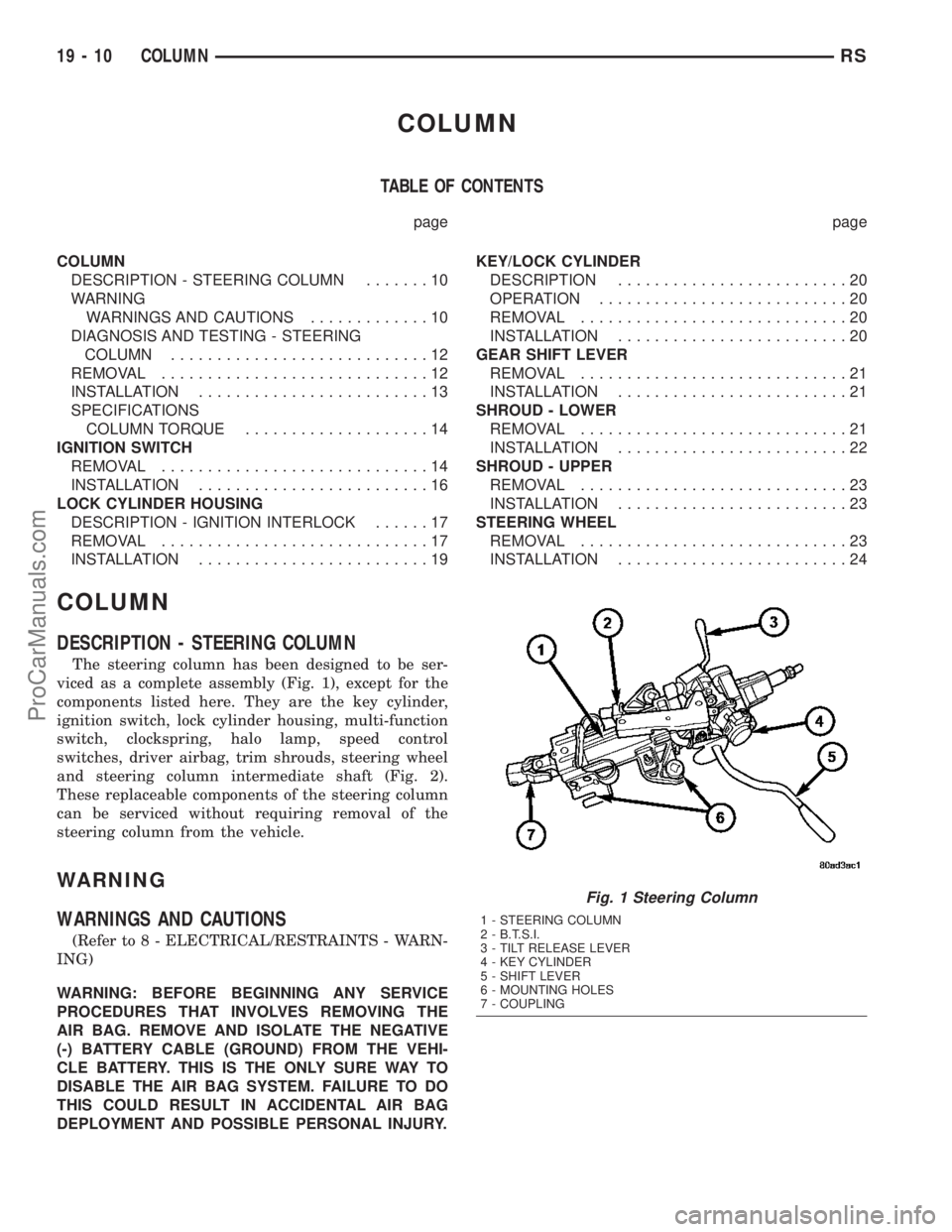
The steering column has been designed to be ser-
viced as a complete assembly (Fig. 1), except for the
components listed here. They are the key cylinder,
ignition switch, lock cylinder housing, multi-function
switch, clockspring, halo lamp, speed control
switches, driver airbag, trim shrouds, steering wheel
and steering column intermediate shaft (Fig. 2).
These replaceable components of the steering column
can be serviced without requiring removal of the
steering column from the vehicle.
WARNING
WARNINGS AND CAUTIONS
(Refer to 8 - ELECTRICAL/RESTRAINTS - WARN-
ING)
WARNING: BEFORE BEGINNING ANY SERVICE
PROCEDURES THAT INVOLVES REMOVING THE
AIR BAG. REMOVE AND ISOLATE THE NEGATIVE
(-) BATTERY CABLE (GROUND) FROM THE VEHI-
CLE BATTERY. THIS IS THE ONLY SURE WAY TO
DISABLE THE AIR BAG SYSTEM. FAILURE TO DO
THIS COULD RESULT IN ACCIDENTAL AIR BAG
DEPLOYMENT AND POSSIBLE PERSONAL INJURY.
Fig. 1 Steering Column
1 - STEERING COLUMN
2 - B.T.S.I.
3 - TILT RELEASE LEVER
4 - KEY CYLINDER
5 - SHIFT LEVER
6 - MOUNTING HOLES
7 - COUPLING
19 - 10 COLUMNRS
ProCarManuals.com
Page 1411 of 2177
INSTALLATION
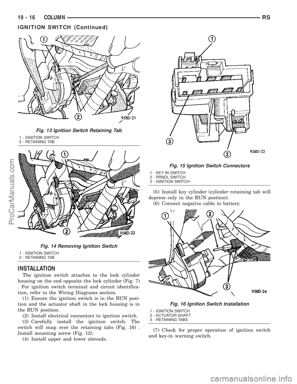
The ignition switch attaches to the lock cylinder
housing on the end opposite the lock cylinder (Fig. 7)
. For ignition switch terminal and circuit identifica-
tion, refer to the Wiring Diagrams section.
(1) Ensure the ignition switch is in the RUN posi-
tion and the actuator shaft in the lock housing is in
the RUN position.
(2) Install electrical connectors to ignition switch.
(3) Carefully install the ignition switch. The
switch will snap over the retaining tabs (Fig. 16) .
Install mounting screw (Fig. 12).
(4) Install upper and lower shrouds.(5) Install key cylinder (cylinder retaining tab will
depress only in the RUN position).
(6) Connect negative cable to battery.
(7) Check for proper operation of ignition switch
and key-in warning switch.
Fig. 13 Ignition Switch Retaining Tab
1 - IGNITION SWITCH
2 - RETAINING TAB
Fig. 14 Removing Ignition Switch
1 - IGNITION SWITCH
2 - RETAINING TAB
Fig. 15 Ignition Switch Connectors
1 - KEY IN SWITCH
2 - PRNDL SWITCH
3 - IGNITION SWITCH
Fig. 16 Ignition Switch Installation
1 - IGNITION SWITCH
2 - ACTUATOR SHAFT
3 - RETAINING TABS
19 - 16 COLUMNRS
IGNITION SWITCH (Continued)
ProCarManuals.com
Page 1412 of 2177
LOCK CYLINDER HOUSING
DESCRIPTION - IGNITION INTERLOCK
All vehicles equipped with automatic transaxles
have an interlock system. The system prevents shift-
ing the vehicle out of Park unless the ignition lock
cylinder is in the Unlock, Run or Start position. In
addition, the operator cannot rotate the key to the
lock position unless the shifter is in the park posi-
tion. On vehicles equipped with floor shift refer to
the - Transaxle for Automatic Transmission Shifter/
Ignition Interlock.
REMOVAL
NOTE: Before proceeding, review all Steering Col-
umn and Airbag Warnings and Cautions. (Refer to
19 - STEERING/COLUMN - WARNING)(Refer to 8 -
ELECTRICAL/RESTRAINTS - WARNING)
(1) Remove battery ground cable terminal from
battery negative post and isolate.
(2) Under instrument panel, remove silencer panel
below lower steering column cover.
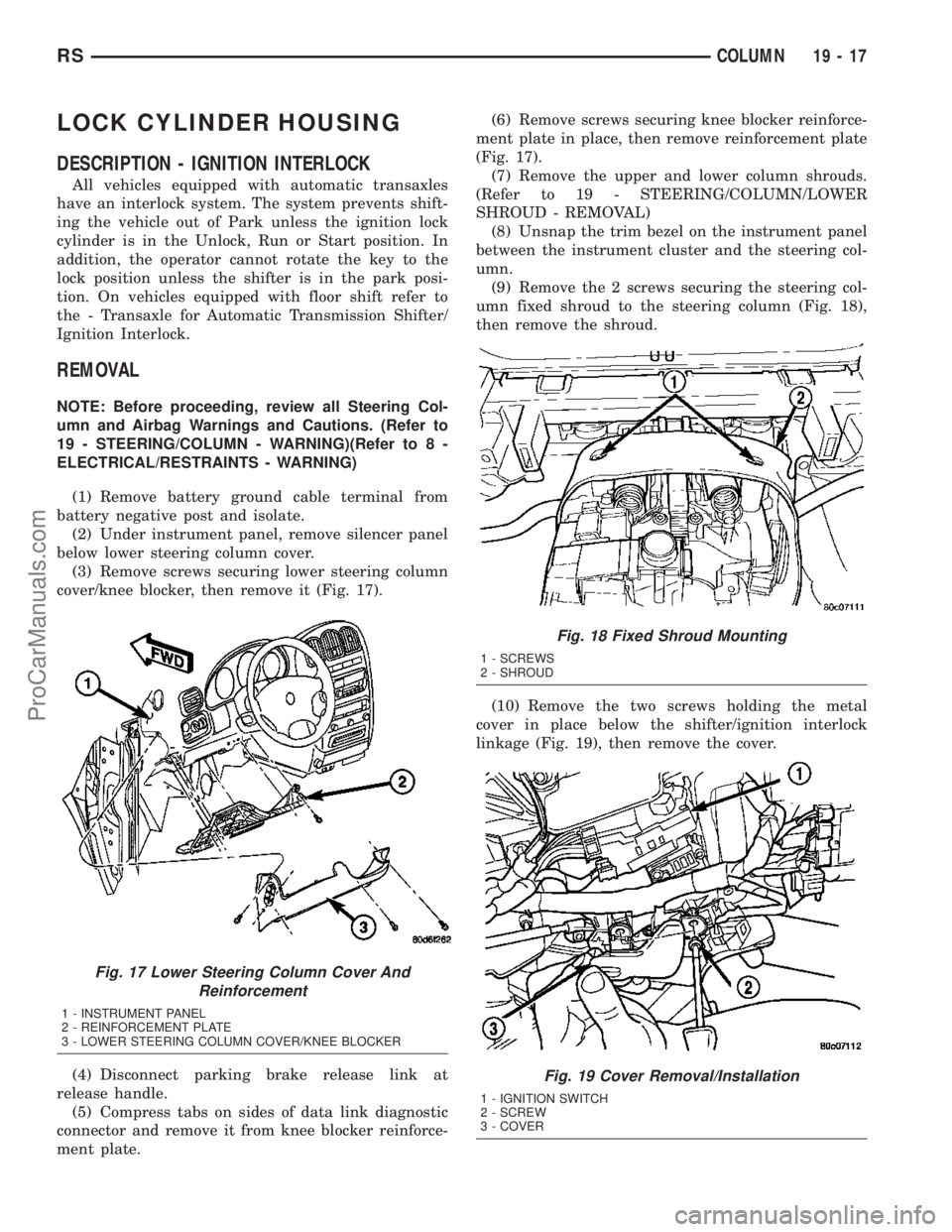
(3) Remove screws securing lower steering column
cover/knee blocker, then remove it (Fig. 17).
(4) Disconnect parking brake release link at
release handle.
(5) Compress tabs on sides of data link diagnostic
connector and remove it from knee blocker reinforce-
ment plate.(6) Remove screws securing knee blocker reinforce-
ment plate in place, then remove reinforcement plate
(Fig. 17).
(7) Remove the upper and lower column shrouds.
(Refer to 19 - STEERING/COLUMN/LOWER
SHROUD - REMOVAL)
(8) Unsnap the trim bezel on the instrument panel
between the instrument cluster and the steering col-
umn.
(9) Remove the 2 screws securing the steering col-
umn fixed shroud to the steering column (Fig. 18),
then remove the shroud.
(10) Remove the two screws holding the metal
cover in place below the shifter/ignition interlock
linkage (Fig. 19), then remove the cover.
Fig. 17 Lower Steering Column Cover And
Reinforcement
1 - INSTRUMENT PANEL
2 - REINFORCEMENT PLATE
3 - LOWER STEERING COLUMN COVER/KNEE BLOCKER
Fig. 18 Fixed Shroud Mounting
1 - SCREWS
2 - SHROUD
Fig. 19 Cover Removal/Installation
1 - IGNITION SWITCH
2 - SCREW
3 - COVER
RSCOLUMN19-17
ProCarManuals.com
Page 1415 of 2177
retaining tab on the lever with the ramp on the link
(Fig. 20), then pushing the two together.
(12) Install the metal cover in place below the
shifter/ignition interlock linkage using the two
screws (Fig. 19).
(13) Install the steering column fixed shroud on
the steering column (Fig. 18) using its 2 mounting
screws.
(14) Install the trim bezel on the instrument panel
above the steering column. The trim bezel is
mounted to the instrument panel using 2 screws (one
on each side of the column) and retaining clips.
(15) Install the lower and upper steering column
shrouds. (Refer to 19 - STEERING/COLUMN/
LOWER SHROUD - INSTALLATION)
(16) Install the knee blocker reinforcement plate
(Fig. 17).
(17) Connect the parking brake release link to the
release handle.
(18) Install the data link diagnostic connector to
the mounting hole in the reinforcement plate.
(19) Install the lower steering column cover/knee
blocker (Fig. 17).
(20) Connect the negative (ground) cable to the
battery terminal.
KEY/LOCK CYLINDER
DESCRIPTION
The lock cylinder is inserted in the end of the
housing opposite the ignition switch.
OPERATION
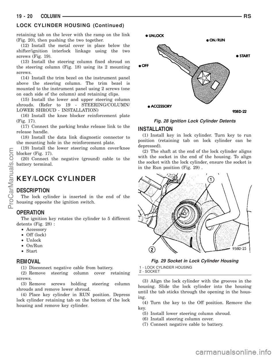
The ignition key rotates the cylinder to 5 different
detents (Fig. 28) :
²Accessory
²Off (lock)
²Unlock
²On/Run
²Start
REMOVAL
(1) Disconnect negative cable from battery.
(2) Remove steering column cover retaining
screws.
(3) Remove screws holding steering column
shrouds and remove lower shroud.
(4) Place key cylinder in RUN position. Depress
lock cylinder retaining tab on the bottom of the lock
housing and remove key cylinder.
INSTALLATION
(1) Install key in lock cylinder. Turn key to run
position (retaining tab on lock cylinder can be
depressed).
(2) The shaft at the end of the lock cylinder aligns
with the socket in the end of the housing. To align
the socket with the lock cylinder, ensure the socket is
in the Run position (Fig. 29) .
(3) Align the lock cylinder with the grooves in the
housing. Slide the lock cylinder into the housing
until the tab sticks through the opening in the hous-
ing.
(4) Turn the key to the Off position. Remove the
key.
(5) Install lower steering column shroud.
(6) Install steering column cover.
(7) Connect negative cable to battery.
Fig. 28 Ignition Lock Cylinder Detents
Fig. 29 Socket in Lock Cylinder Housing
1 - LOCK CYLINDER HOUSING
2 - SOCKET
19 - 20 COLUMNRS
LOCK CYLINDER HOUSING (Continued)
ProCarManuals.com
Page 1653 of 2177
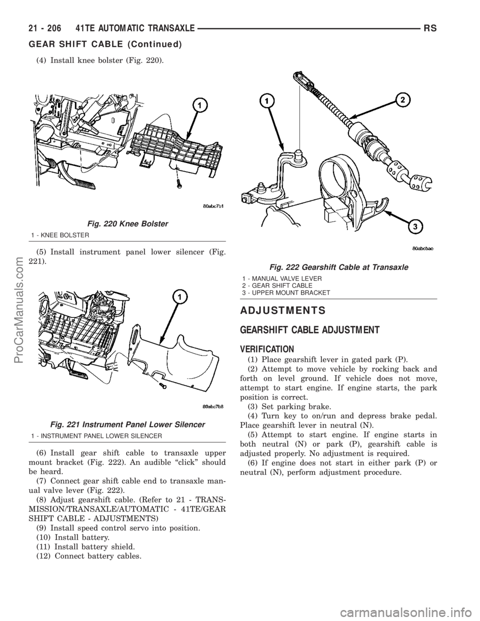
(4) Install knee bolster (Fig. 220).
(5) Install instrument panel lower silencer (Fig.
221).
(6) Install gear shift cable to transaxle upper
mount bracket (Fig. 222). An audible ªclickº should
be heard.
(7) Connect gear shift cable end to transaxle man-
ual valve lever (Fig. 222).
(8) Adjust gearshift cable. (Refer to 21 - TRANS-
MISSION/TRANSAXLE/AUTOMATIC - 41TE/GEAR
SHIFT CABLE - ADJUSTMENTS)
(9) Install speed control servo into position.
(10) Install battery.
(11) Install battery shield.
(12) Connect battery cables.
ADJUSTMENTS
GEARSHIFT CABLE ADJUSTMENT
VERIFICATION
(1) Place gearshift lever in gated park (P).
(2) Attempt to move vehicle by rocking back and
forth on level ground. If vehicle does not move,
attempt to start engine. If engine starts, the park
position is correct.
(3) Set parking brake.
(4) Turn key to on/run and depress brake pedal.
Place gearshift lever in neutral (N).
(5) Attempt to start engine. If engine starts in
both neutral (N) or park (P), gearshift cable is
adjusted properly. No adjustment is required.
(6) If engine does not start in either park (P) or
neutral (N), perform adjustment procedure.
Fig. 220 Knee Bolster
1 - KNEE BOLSTER
Fig. 221 Instrument Panel Lower Silencer
1 - INSTRUMENT PANEL LOWER SILENCER
Fig. 222 Gearshift Cable at Transaxle
1 - MANUAL VALVE LEVER
2 - GEAR SHIFT CABLE
3 - UPPER MOUNT BRACKET
21 - 206 41TE AUTOMATIC TRANSAXLERS
GEAR SHIFT CABLE (Continued)
ProCarManuals.com
Page 1680 of 2177
INSTALLATION
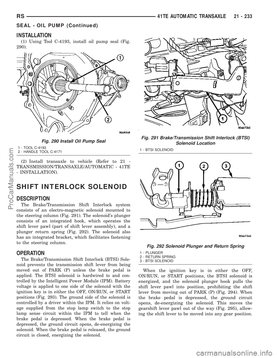
(1) Using Tool C-4193, install oil pump seal (Fig.
290).
(2) Install transaxle to vehicle (Refer to 21 -
TRANSMISSION/TRANSAXLE/AUTOMATIC - 41TE
- INSTALLATION).
SHIFT INTERLOCK SOLENOID
DESCRIPTION
The Brake/Transmission Shift Interlock system
consists of an electro-magnetic solenoid mounted to
the steering column (Fig. 291). The solenoid's plunger
consists of an integrated hook, which operates the
shift lever pawl (part of shift lever assembly), and a
plunger return spring (Fig. 292). The solenoid also
has an integrated bracket, which facilitates fastening
to the steering column.
OPERATION
The Brake/Transmission Shift Interlock (BTSI) Sole-
noid prevents the transmission shift lever from being
moved out of PARK (P) unless the brake pedal is
applied. The BTSI solenoid is hardwired to and con-
trolled by the Intelligent Power Module (IPM). Battery
voltage is applied to one side of the solenoid with the
ignition key is in either the OFF, ON/RUN, or START
positions (Fig. 293). The ground side of the solenoid is
controlled by a driver within the IPM. It relies on volt-
age supplied from the stop lamp switch to the stop
lamp sense circuit within the IPM to tell when the
brake pedal is depressed. When the brake pedal is
depressed, the ground circuit opens, de-energizing the
solenoid. When the brake pedal is released, the ground
circuit is closed, energizing the solenoid.
When the ignition key is in either the OFF,
ON/RUN, or START positions, the BTSI solenoid is
energized, and the solenoid plunger hook pulls the
shift lever pawl into position, prohibiting the shift
lever from moving out of PARK (P) (Fig. 294). When
the brake pedal is depressed, the ground circuit
opens, de-energizing the solenoid. This moves the
gearshift lever pawl out of the way (Fig. 295), allow-
ing the shift lever to be moved into any gear position.
Fig. 290 Install Oil Pump Seal
1 - TOOL C-4193
2 - HANDLE TOOL C-4171
Fig. 291 Brake/Transmission Shift Interlock (BTSI)
Solenoid Location
1 - BTSI SOLENOID
Fig. 292 Solenoid Plunger and Return Spring
1 - PLUNGER
2 - RETURN SPRING
3 - BTSI SOLENOID
RS41TE AUTOMATIC TRANSAXLE21 - 233
SEAL - OIL PUMP (Continued)
ProCarManuals.com
Page 1682 of 2177
DIAGNOSIS AND TESTING - BRAKE/
TRANSMISSION SHIFT INTERLOCK SOLENOID
For intended BTSI system operation, refer to the
following chart:
ACTION EXPECTED RESPONSE
1. Turn key to the9OFF9
position.1. Shifter CAN be shifted
out of park with brake
pedal applied.
2. Turn key to the
9ON/RUN9position.2. Shifter CANNOT be
shifted out of park.
3. Turn key to the
9ON/RUN9position and
depress the brake pedal.3. Shifter CAN be shifted
out of park.
4. Leave shifter in any
gear and try to return key
to the9LOCK9or9ACC9
position.4. Key cannot be
returned to the9LOCK9or
9ACC9position.
5. Return shifter to
9PARK9and try to remove
the key.5. Key can be removed
(after returning to9LOCK9
position).
6. With the key removed,
try to shift out of9PARK9.6. Shifter cannot be
shifted out of9PARK9.
NOTE: Any failure to meet these expected
responses requires system repair. Refer to the
appropriate Diagnostic Information.
REMOVAL
(1) Disconnect battery negative cable.
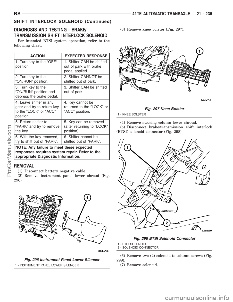
(2) Remove instrument panel lower shroud (Fig.
296).(3) Remove knee bolster (Fig. 297).
(4) Remove steering column lower shroud.
(5) Disconnect brake/transmission shift interlock
(BTSI) solenoid connector (Fig. 298).
(6) Remove two (2) solenoid-to-column screws (Fig.
299).
(7) Remove solenoid.
Fig. 296 Instrument Panel Lower Silencer
1 - INSTRUMENT PANEL LOWER SILENCER
Fig. 297 Knee Bolster
1 - KNEE BOLSTER
Fig. 298 BTSI Solenoid Connector
1 - BTSI SOLENOID
2 - SOLENOID CONNECTOR
RS41TE AUTOMATIC TRANSAXLE21 - 235
SHIFT INTERLOCK SOLENOID (Continued)
ProCarManuals.com
Page 1695 of 2177
OPERATION
The relay is supplied fused B+ voltage, energized
by the PCM/TCM, and is used to supply power to the
solenoid pack when the transmission is in normal
operating mode. When the relay is ªoffº, no power is
supplied to the solenoid pack and the transmission is
in ªlimp-inº mode. After a controller reset (ignition
key turned to the ªrunº position or after cranking
engine), the PCM/TCM energizes the relay. Prior to
this, the PCM/TCM verifies that the contacts are
open by checking for no voltage at the switched bat-
tery terminals. After this is verified, the voltage at
the solenoid pack pressure switches is checked. After
the relay is energized, the PCM/TCM monitors the
terminals to verify that the voltage is greater than 3
volts.
TRANSMISSION RANGE
SENSOR
DESCRIPTION
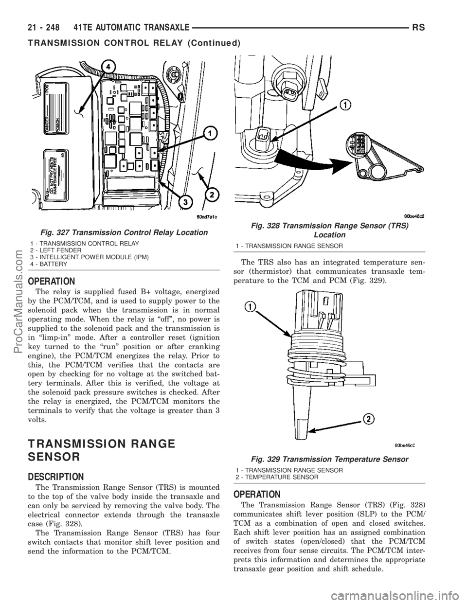
The Transmission Range Sensor (TRS) is mounted
to the top of the valve body inside the transaxle and
can only be serviced by removing the valve body. The
electrical connector extends through the transaxle
case (Fig. 328).
The Transmission Range Sensor (TRS) has four
switch contacts that monitor shift lever position and
send the information to the PCM/TCM.The TRS also has an integrated temperature sen-
sor (thermistor) that communicates transaxle tem-
perature to the TCM and PCM (Fig. 329).
OPERATION
The Transmission Range Sensor (TRS) (Fig. 328)
communicates shift lever position (SLP) to the PCM/
TCM as a combination of open and closed switches.
Each shift lever position has an assigned combination
of switch states (open/closed) that the PCM/TCM
receives from four sense circuits. The PCM/TCM inter-
prets this information and determines the appropriate
transaxle gear position and shift schedule.
Fig. 327 Transmission Control Relay Location
1 - TRANSMISSION CONTROL RELAY
2 - LEFT FENDER
3 - INTELLIGENT POWER MODULE (IPM)
4 - BATTERY
Fig. 328 Transmission Range Sensor (TRS)
Location
1 - TRANSMISSION RANGE SENSOR
Fig. 329 Transmission Temperature Sensor
1 - TRANSMISSION RANGE SENSOR
2 - TEMPERATURE SENSOR
21 - 248 41TE AUTOMATIC TRANSAXLERS
TRANSMISSION CONTROL RELAY (Continued)
ProCarManuals.com