2003 CHRYSLER CARAVAN battery
[x] Cancel search: batteryPage 1420 of 2177
steering wheel onto the steering column shaft by
hand. Use care not to pinch any wiring.
NOTE: Before installing the damper on the steering
wheel, inspect the damper to ensure the rubber iso-
lator on the damper is not deteriorated or damaged.
If the damper is installed with a damaged isolator, a
buzz, squeak or rattle condition may develop.
(4) Install the steering wheel damper on the steer-
ing wheel (Fig. 36).
(5) Install the steering wheel retaining nut.
Tighten the steering wheel retaining nut to 61 N´m
(45 ft. lbs.) torque.(6) If the steering wheel is equipped with remote
radio controls, connect the wiring connector to the
clockspring (Fig. 36).
(7) Connect the airbag squib wiring connectors to
the airbag and the horn/speed control switch pigtail
connector to the clockspring (Fig. 35).
(8) Install the driver airbag in the steering wheel.
Install and tighten the airbag attaching bolts to 10
N´m (90 in. lbs.) torque.
(9) To properly connect the battery and test the
airbag system, (Refer to 8 - ELECTRICAL/RE-
STRAINTS - DIAGNOSIS AND TESTING).
RSCOLUMN19-25
STEERING WHEEL (Continued)
ProCarManuals.com
Page 1433 of 2177
REMOVAL
REMOVAL - PUMP (2.4L ENGINE)
(1) Remove the (-) negative battery cable from the
battery and isolate cable.
(2) Remove the cap from the power steering fluid
reservoir.
(3) Using a siphon pump, remove as much power
steering fluid as possible from the power steering
fluid reservoir.
(4) Raise the vehicle on jack stands or centered on
a frame contact type hoist. See Hoisting in Lubrica-
tion and Maintenance.
(5) Disconnect the oxygen sensor wiring harness
from the vehicle wiring harness at the rear engine
mount bracket.
NOTE: The exhaust system needs to be removed
from the engine to allow for an area to remove the
power steering pump from the vehicle.
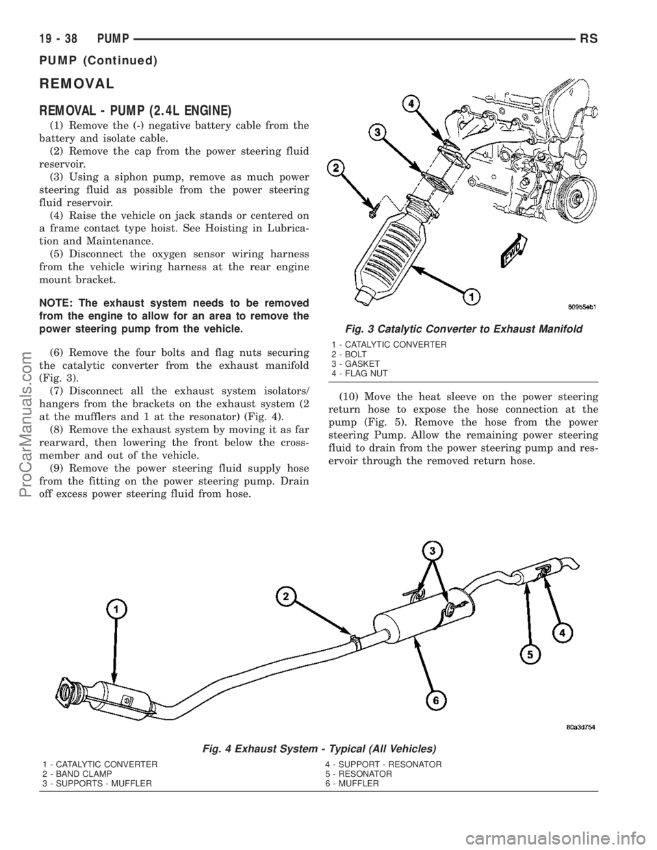
(6) Remove the four bolts and flag nuts securing
the catalytic converter from the exhaust manifold
(Fig. 3).
(7) Disconnect all the exhaust system isolators/
hangers from the brackets on the exhaust system (2
at the mufflers and 1 at the resonator) (Fig. 4).
(8) Remove the exhaust system by moving it as far
rearward, then lowering the front below the cross-
member and out of the vehicle.
(9) Remove the power steering fluid supply hose
from the fitting on the power steering pump. Drain
off excess power steering fluid from hose.(10) Move the heat sleeve on the power steering
return hose to expose the hose connection at the
pump (Fig. 5). Remove the hose from the power
steering Pump. Allow the remaining power steering
fluid to drain from the power steering pump and res-
ervoir through the removed return hose.
Fig. 3 Catalytic Converter to Exhaust Manifold
1 - CATALYTIC CONVERTER
2 - BOLT
3 - GASKET
4 - FLAG NUT
Fig. 4 Exhaust System - Typical (All Vehicles)
1 - CATALYTIC CONVERTER 4 - SUPPORT - RESONATOR
2 - BAND CLAMP 5 - RESONATOR
3 - SUPPORTS - MUFFLER 6 - MUFFLER
19 - 38 PUMPRS
PUMP (Continued)
ProCarManuals.com
Page 1435 of 2177
(17) Remove the 3 bolts attaching the front
bracket to the power steering pump and separate the
power steering pump from the front bracket.
(18) If the power steering pump pulley needs to be
transferred, (Refer to 19 - STEERING/PUMP - DIS-
ASSEMBLY).
REMOVAL - PUMP (3.3L/3.8L ENGINE)
(1) Remove the (-) negative battery cable from the
battery and isolate cable.
(2) Remove the wiper module (unit)(Refer to 8 -
ELECTRICAL/WIPERS/WASHERS/WIPER MOD-
ULE - REMOVAL).
(3) Raise the vehicle. (Refer to LUBRICATION &
MAINTENANCE/HOISTING - STANDARD PROCE-
DURE)
(4) Remove the drive belt splash shield.
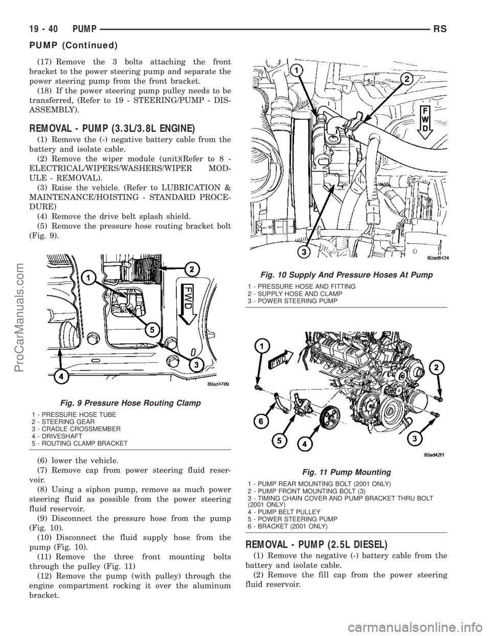
(5) Remove the pressure hose routing bracket bolt
(Fig. 9).
(6) lower the vehicle.
(7) Remove cap from power steering fluid reser-
voir.
(8) Using a siphon pump, remove as much power
steering fluid as possible from the power steering
fluid reservoir.
(9) Disconnect the pressure hose from the pump
(Fig. 10).
(10) Disconnect the fluid supply hose from the
pump (Fig. 10).
(11) Remove the three front mounting bolts
through the pulley (Fig. 11)
(12) Remove the pump (with pulley) through the
engine compartment rocking it over the aluminum
bracket.
REMOVAL - PUMP (2.5L DIESEL)
(1) Remove the negative (-) battery cable from the
battery and isolate cable.
(2) Remove the fill cap from the power steering
fluid reservoir.
Fig. 9 Pressure Hose Routing Clamp
1 - PRESSURE HOSE TUBE
2 - STEERING GEAR
3 - CRADLE CROSSMEMBER
4 - DRIVESHAFT
5 - ROUTING CLAMP BRACKET
Fig. 10 Supply And Pressure Hoses At Pump
1 - PRESSURE HOSE AND FITTING
2 - SUPPLY HOSE AND CLAMP
3 - POWER STEERING PUMP
Fig. 11 Pump Mounting
1 - PUMP REAR MOUNTING BOLT (2001 ONLY)
2 - PUMP FRONT MOUNTING BOLT (3)
3 - TIMING CHAIN COVER AND PUMP BRACKET THRU BOLT
(2001 ONLY)
4 - PUMP BELT PULLEY
5 - POWER STEERING PUMP
6 - BRACKET (2001 ONLY)
19 - 40 PUMPRS
PUMP (Continued)
ProCarManuals.com
Page 1437 of 2177
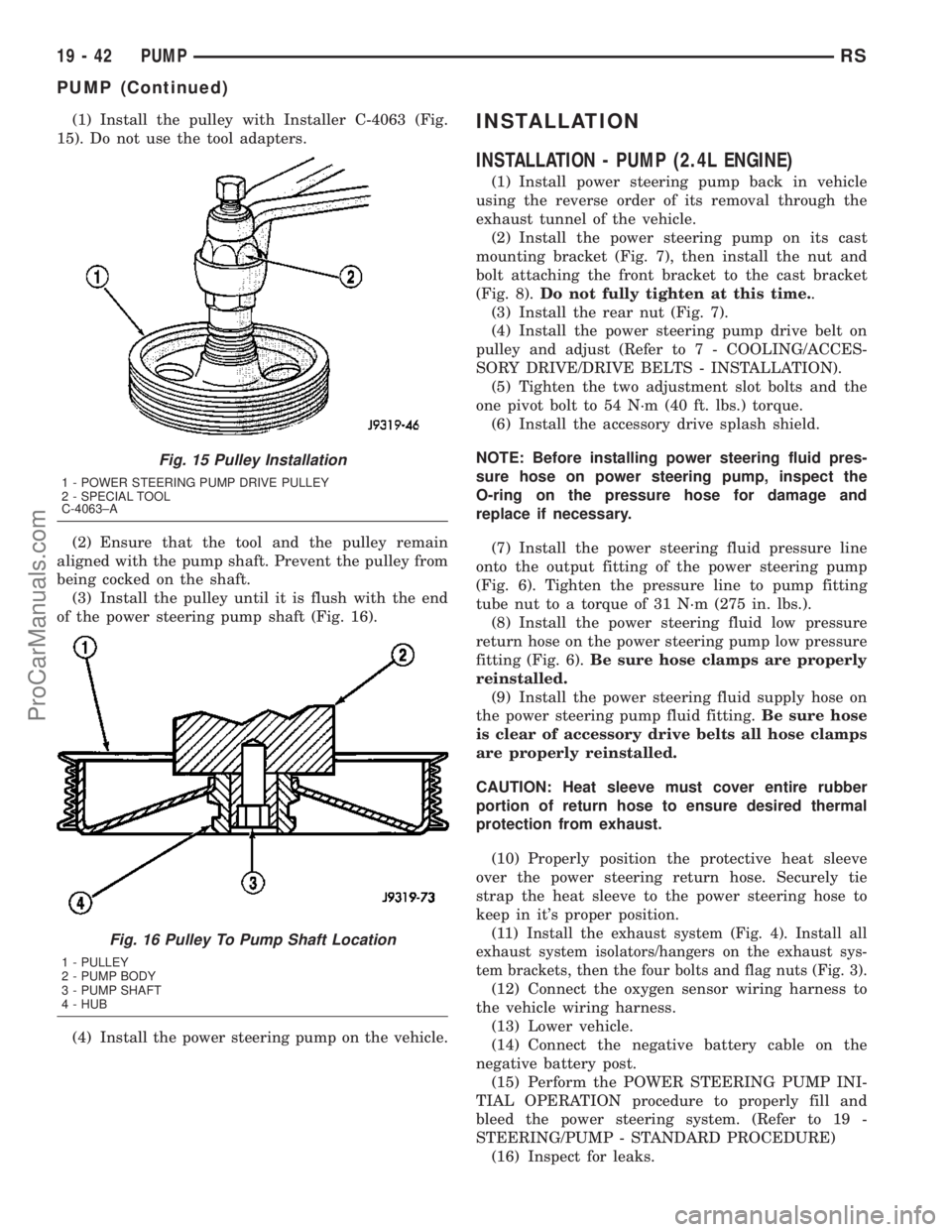
(1) Install the pulley with Installer C-4063 (Fig.
15). Do not use the tool adapters.
(2) Ensure that the tool and the pulley remain
aligned with the pump shaft. Prevent the pulley from
being cocked on the shaft.
(3) Install the pulley until it is flush with the end
of the power steering pump shaft (Fig. 16).
(4) Install the power steering pump on the vehicle.INSTALLATION
INSTALLATION - PUMP (2.4L ENGINE)
(1) Install power steering pump back in vehicle
using the reverse order of its removal through the
exhaust tunnel of the vehicle.
(2) Install the power steering pump on its cast
mounting bracket (Fig. 7), then install the nut and
bolt attaching the front bracket to the cast bracket
(Fig. 8).Do not fully tighten at this time..
(3) Install the rear nut (Fig. 7).
(4) Install the power steering pump drive belt on
pulley and adjust (Refer to 7 - COOLING/ACCES-
SORY DRIVE/DRIVE BELTS - INSTALLATION).
(5) Tighten the two adjustment slot bolts and the
one pivot bolt to 54 N´m (40 ft. lbs.) torque.
(6) Install the accessory drive splash shield.
NOTE: Before installing power steering fluid pres-
sure hose on power steering pump, inspect the
O-ring on the pressure hose for damage and
replace if necessary.
(7) Install the power steering fluid pressure line
onto the output fitting of the power steering pump
(Fig. 6). Tighten the pressure line to pump fitting
tube nut to a torque of 31 N´m (275 in. lbs.).
(8) Install the power steering fluid low pressure
return hose on the power steering pump low pressure
fitting (Fig. 6).Be sure hose clamps are properly
reinstalled.
(9) Install the power steering fluid supply hose on
the power steering pump fluid fitting.Be sure hose
is clear of accessory drive belts all hose clamps
are properly reinstalled.
CAUTION: Heat sleeve must cover entire rubber
portion of return hose to ensure desired thermal
protection from exhaust.
(10) Properly position the protective heat sleeve
over the power steering return hose. Securely tie
strap the heat sleeve to the power steering hose to
keep in it's proper position.
(11)
Install the exhaust system (Fig. 4). Install all
exhaust system isolators/hangers on the exhaust sys-
tem brackets, then the four bolts and flag nuts (Fig. 3).
(12) Connect the oxygen sensor wiring harness to
the vehicle wiring harness.
(13) Lower vehicle.
(14) Connect the negative battery cable on the
negative battery post.
(15) Perform the POWER STEERING PUMP INI-
TIAL OPERATION procedure to properly fill and
bleed the power steering system. (Refer to 19 -
STEERING/PUMP - STANDARD PROCEDURE)
(16) Inspect for leaks.
Fig. 15 Pulley Installation
1 - POWER STEERING PUMP DRIVE PULLEY
2 - SPECIAL TOOL
C-4063±A
Fig. 16 Pulley To Pump Shaft Location
1 - PULLEY
2 - PUMP BODY
3 - PUMP SHAFT
4 - HUB
19 - 42 PUMPRS
PUMP (Continued)
ProCarManuals.com
Page 1438 of 2177
INSTALLATION - PUMP (3.3L/3.8L ENGINE)
(1) Install power steering pump back in vehicle
using the reverse order of its removal through the
engine compartment of the vehicle.
(2) Install the power steering pump on its mount-
ing bracket.
(3) Install the 3 front power steering pump mount-
ing bolts (Fig. 11). Tighten the 3 front power steering
pump mounting bolts to a torque of 54 N´m (40 ft.
lbs.).
NOTE: Before installing power steering pressure
hose on power steering pump, inspect the O-ring
on the power steering pressure hose for damage
and replace if required.
(4) Install the power steering fluid pressure line
into the pressure output fitting of the power steering
pump (Fig. 10).Do not fully tighten tube nut at
this time.
(5) Install the power steering fluid supply hose on
the power steering pump supply fitting (Fig. 10).Be
sure hose clamp is properly installed.
(6) Raise the vehicle.
(7) Install the routing clip on the engine for the
pressure hose (Fig. 9) and tighten fastener.
(8) Install the serpentine drive belt (Refer to 7 -
COOLING/ACCESSORY DRIVE/DRIVE BELTS -
INSTALLATION).
(9) Install the drive belt splash shield.
(10) Lower the vehicle.
(11) Tighten the pressure line to pump pressure
fitting tube nut to a torque of 31 N´m (275 in. lbs.).
(12) Install the wiper module (unit)(Refer to 8 -
ELECTRICAL/WIPERS/WASHERS/WIPER MOD-
ULE - INSTALLATION).
(13) Connect the negative battery cable on the
negative battery post.
(14) Fill and bleed the power steering system
using the Power Steering Pump Initial Operation
Procedure (Refer to 19 - STEERING/PUMP - STAN-
DARD PROCEDURE).
(15) Inspect for leaks.
INSTALLATION - PUMP (2.5L DIESEL)
(1) Install the power steering pump on its cast
mounting bracket.
(2) Install the three front power steering pump
mounting bolts. Tighten the mounting bolts to a
torque of 54 N´m (40 ft. lbs.).
(3) Install the rear mounting bolt fastening the
stamped bracket to the cast bracket (Fig. 13).
Tighten the mounting bolt to a torque of 54 N´m (40
ft. lbs.).NOTE: Before installing power steering pressure
hose on power steering pump, inspect the O-ring
on the power steering pressure hose for damage
and replace if required.
(4) Install the power steering fluid pressure hose
fitting into the pressure port of the power steering
pump (Fig. 12). Tighten the pressure line to pump
fitting tube nut to a torque of 31 N´m (275 in. lbs.).
(5) Install the power steering fluid supply hose on
the power steering pump supply fitting (Fig. 12).Be
sure hose clamp is properly reinstalled.
(6) Install the accessary drive belt (Refer to 7 -
COOLING/ACCESSORY DRIVE/DRIVE BELTS -
INSTALLATION).
(7) Install the splash shields below the engine
compartment.
(8) Lower the vehicle.
(9) Connect the negative (-) battery cable on the
negative battery post.
(10) Fill and bleed the power steering system
using the Power Steering Pump Initial Operation
Procedure (Refer to 19 - STEERING/PUMP - STAN-
DARD PROCEDURE).
(11) Inspect for leaks.
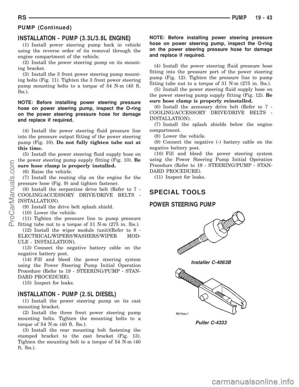
SPECIAL TOOLS
POWER STEERING PUMP
Installer C-4063B
Puller C-4333
RSPUMP19-43
PUMP (Continued)
ProCarManuals.com
Page 1446 of 2177
(2) Align routing clip located toward center of sup-
ply hose with hole in bracket on cylinder head cover
and push into place (Fig. 21).
(3) Install supply hose onto reservoir (Fig. 21).
Slide the hose clamp into position on fluid reservoir
and attach it.Be sure hose clamp in installed
past bead on fluid reservoir fitting.
(4) Fill and bleed power steering system using
Power Steering Pump Initial Operation Procedure.
(Refer to 19 - STEERING/PUMP - STANDARD PRO-
CEDURE)
(5) Inspect system for leaks.
RESERVOIR - POWER
STEERING FLUID
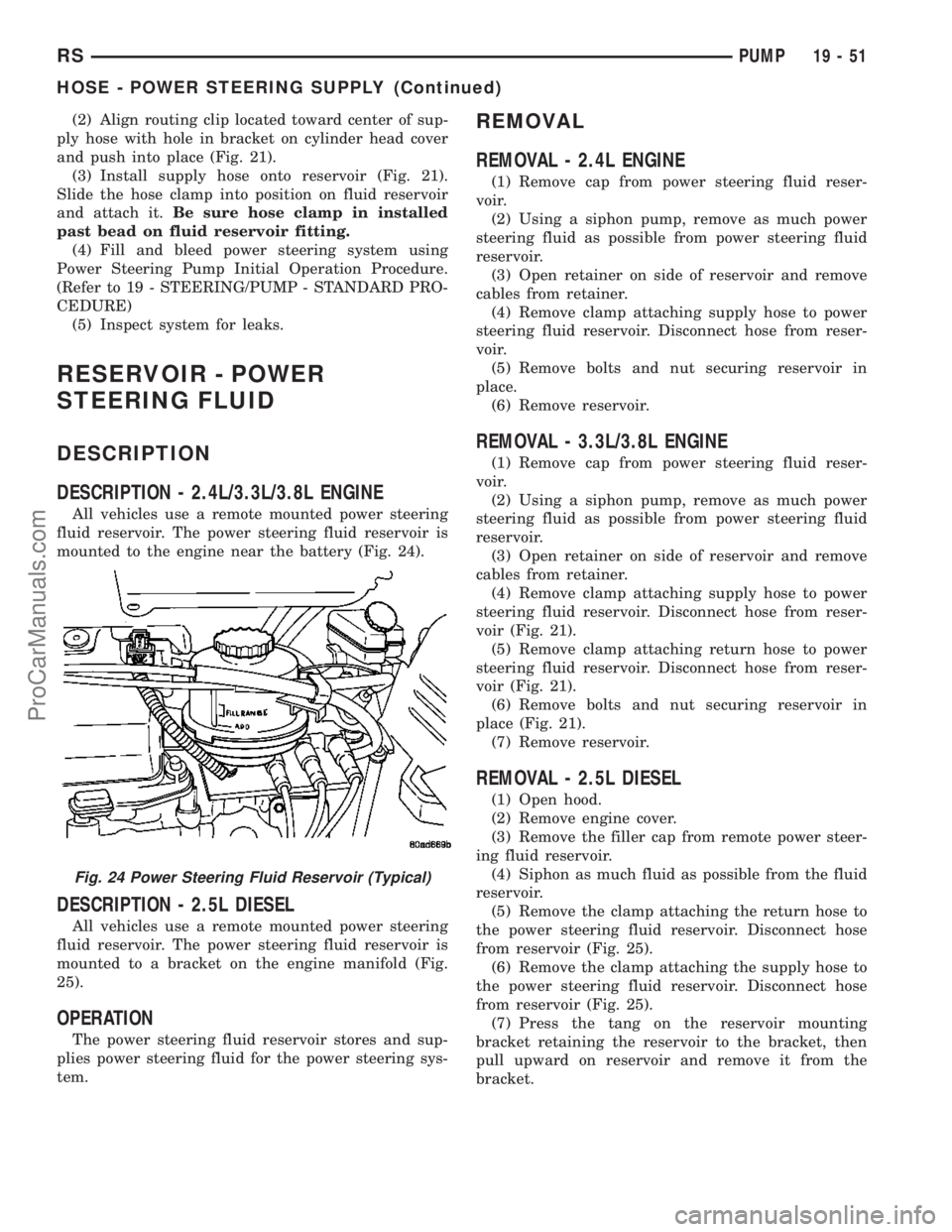
DESCRIPTION
DESCRIPTION - 2.4L/3.3L/3.8L ENGINE
All vehicles use a remote mounted power steering
fluid reservoir. The power steering fluid reservoir is
mounted to the engine near the battery (Fig. 24).
DESCRIPTION - 2.5L DIESEL
All vehicles use a remote mounted power steering
fluid reservoir. The power steering fluid reservoir is
mounted to a bracket on the engine manifold (Fig.
25).
OPERATION
The power steering fluid reservoir stores and sup-
plies power steering fluid for the power steering sys-
tem.
REMOVAL
REMOVAL - 2.4L ENGINE
(1) Remove cap from power steering fluid reser-
voir.
(2) Using a siphon pump, remove as much power
steering fluid as possible from power steering fluid
reservoir.
(3) Open retainer on side of reservoir and remove
cables from retainer.
(4) Remove clamp attaching supply hose to power
steering fluid reservoir. Disconnect hose from reser-
voir.
(5) Remove bolts and nut securing reservoir in
place.
(6) Remove reservoir.
REMOVAL - 3.3L/3.8L ENGINE
(1) Remove cap from power steering fluid reser-
voir.
(2) Using a siphon pump, remove as much power
steering fluid as possible from power steering fluid
reservoir.
(3) Open retainer on side of reservoir and remove
cables from retainer.
(4) Remove clamp attaching supply hose to power
steering fluid reservoir. Disconnect hose from reser-
voir (Fig. 21).
(5) Remove clamp attaching return hose to power
steering fluid reservoir. Disconnect hose from reser-
voir (Fig. 21).
(6) Remove bolts and nut securing reservoir in
place (Fig. 21).
(7) Remove reservoir.
REMOVAL - 2.5L DIESEL
(1) Open hood.
(2) Remove engine cover.
(3) Remove the filler cap from remote power steer-
ing fluid reservoir.
(4) Siphon as much fluid as possible from the fluid
reservoir.
(5) Remove the clamp attaching the return hose to
the power steering fluid reservoir. Disconnect hose
from reservoir (Fig. 25).
(6) Remove the clamp attaching the supply hose to
the power steering fluid reservoir. Disconnect hose
from reservoir (Fig. 25).
(7) Press the tang on the reservoir mounting
bracket retaining the reservoir to the bracket, then
pull upward on reservoir and remove it from the
bracket.
Fig. 24 Power Steering Fluid Reservoir (Typical)
RSPUMP19-51
HOSE - POWER STEERING SUPPLY (Continued)
ProCarManuals.com
Page 1480 of 2177
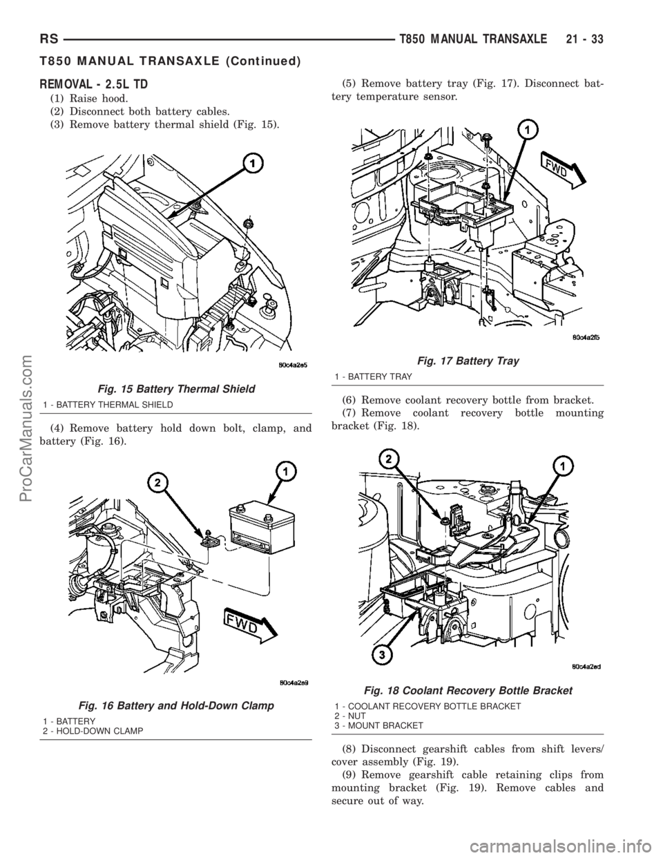
REMOVAL - 2.5L TD
(1) Raise hood.
(2) Disconnect both battery cables.
(3) Remove battery thermal shield (Fig. 15).
(4) Remove battery hold down bolt, clamp, and
battery (Fig. 16).(5) Remove battery tray (Fig. 17). Disconnect bat-
tery temperature sensor.
(6) Remove coolant recovery bottle from bracket.
(7) Remove coolant recovery bottle mounting
bracket (Fig. 18).
(8) Disconnect gearshift cables from shift levers/
cover assembly (Fig. 19).
(9) Remove gearshift cable retaining clips from
mounting bracket (Fig. 19). Remove cables and
secure out of way.
Fig. 15 Battery Thermal Shield
1 - BATTERY THERMAL SHIELD
Fig. 16 Battery and Hold-Down Clamp
1 - BATTERY
2 - HOLD-DOWN CLAMP
Fig. 17 Battery Tray
1 - BATTERY TRAY
Fig. 18 Coolant Recovery Bottle Bracket
1 - COOLANT RECOVERY BOTTLE BRACKET
2 - NUT
3 - MOUNT BRACKET
RST850 MANUAL TRANSAXLE21-33
T850 MANUAL TRANSAXLE (Continued)
ProCarManuals.com
Page 1499 of 2177
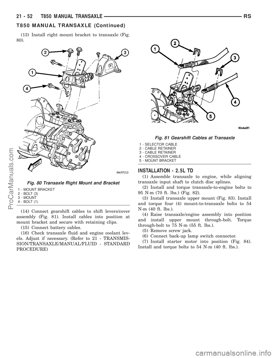
(13) Install right mount bracket to transaxle (Fig.
80).
(14) Connect gearshift cables to shift levers/cover
assembly (Fig. 81). Install cables into position at
mount bracket and secure with retaining clips.
(15) Connect battery cables.
(16) Check transaxle fluid and engine coolant lev-
els. Adjust if necessary. (Refer to 21 - TRANSMIS-
SION/TRANSAXLE/MANUAL/FLUID - STANDARD
PROCEDURE)
INSTALLATION - 2.5L TD
(1) Assemble transaxle to engine, while aligning
transaxle input shaft to clutch disc splines.
(2) Install and torque transaxle-to-engine bolts to
95 N´m (70 ft. lbs.) (Fig. 82).
(3) Install transaxle upper mount (Fig. 83). Install
and torque four (4) mount-to-transaxle bolts to 54
N´m (40 ft. lbs.).
(4) Raise transaxle/engine assembly into position
and install upper mount through-bolt. Torque
through-bolt to 75 N´m (55 ft. lbs.).
(5) Remove screw jack.
(6) Connect back-up lamp switch connector.
(7) Install starter motor into position (Fig. 84).
Install and torque bolts to 54 N´m (40 ft. lbs.).
Fig. 80 Transaxle Right Mount and Bracket
1 - MOUNT BRACKET
2 - BOLT (3)
3 - MOUNT
4 - BOLT (1)
Fig. 81 Gearshift Cables at Transaxle
1 - SELECTOR CABLE
2 - CABLE RETAINER
3 - CABLE RETAINER
4 - CROSSOVER CABLE
5 - MOUNT BRACKET
21 - 52 T850 MANUAL TRANSAXLERS
T850 MANUAL TRANSAXLE (Continued)
ProCarManuals.com