2003 CHRYSLER CARAVAN brake
[x] Cancel search: brakePage 1326 of 2177
²Mounting surface distortion by using a straight-
edge and thickness gauge.
INSTALLATION - UPPER INTAKE MANIFOLD
(1) If the following components were removed from
manifold, install and tighten to specifications:
CAUTION: The special screws used for the compos-
ite manifold attached components must be installed
slowly using hand tools only. This requirement is to
prevent the melting of material that causes stripped
threads. If threads become stripped, an oversize
repair screw is available. For more information and
procedure (Refer to 9 - ENGINE/MANIFOLDS/IN-
TAKE MANIFOLD - STANDARD PROCEDURE - MAN-
IFOLD STRIPPED THREAD REPAIR).
²MAP sensor - 1.7 N´m (15 in. lbs.)
²Throttle cable bracket - 5.6 N´m (50 in. lbs.)
(2) Remove covering on lower intake manifold and
clean surfaces.
(3) Inspect manifold gasket condition. Gaskets can
be re-used, if not damaged. To replace, remove gasket
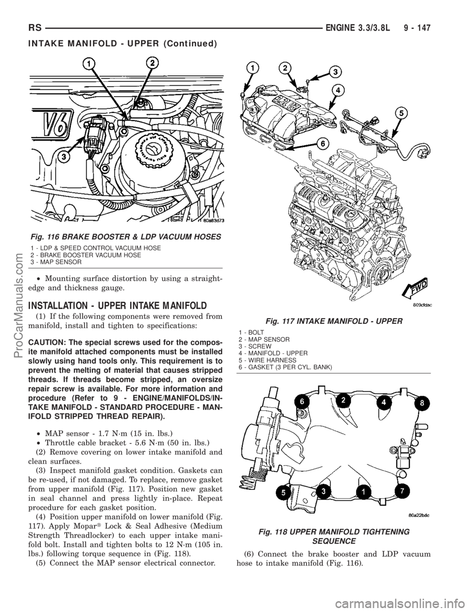
from upper manifold (Fig. 117). Position new gasket
in seal channel and press lightly in-place. Repeat
procedure for each gasket position.
(4) Position upper manifold on lower manifold (Fig.
117). Apply MopartLock & Seal Adhesive (Medium
Strength Threadlocker) to each upper intake mani-
fold bolt. Install and tighten bolts to 12 N´m (105 in.
lbs.) following torque sequence in (Fig. 118).
(5) Connect the MAP sensor electrical connector.(6) Connect the brake booster and LDP vacuum
hose to intake manifold (Fig. 116).
Fig. 116 BRAKE BOOSTER & LDP VACUUM HOSES
1 - LDP & SPEED CONTROL VACUUM HOSE
2 - BRAKE BOOSTER VACUUM HOSE
3 - MAP SENSOR
Fig. 117 INTAKE MANIFOLD - UPPER
1 - BOLT
2 - MAP SENSOR
3 - SCREW
4 - MANIFOLD - UPPER
5 - WIRE HARNESS
6 - GASKET (3 PER CYL. BANK)
Fig. 118 UPPER MANIFOLD TIGHTENING
SEQUENCE
RSENGINE 3.3/3.8L9 - 147
INTAKE MANIFOLD - UPPER (Continued)
ProCarManuals.com
Page 1340 of 2177
(4) Following the PEP module instruction manual,
connect all required cables to the DRB IIItand PEP
module. Select the available menu options on the
DRBIIItdisplay screen for using the digital pressure
gauge function.
(5) Apply the park brake and start the engine.
(6) With transmission in Park or Neutral, raise
engine speed to 2000 RPM. Monitor the pressure
readings on the DRBIIIt. Back pressure should not
exceed specified limit. Refer to specification in table
below EXHAUST BACK PRESSURE LIMITS .
(7) If pressure exceeds maximum limits, inspect
exhaust system for restricted component. For further
catalytic converter inspection procedures, (Refer to 11
- EXHAUST SYSTEM/CATALYTIC CONVERTER -
INSPECTION). Replace component(s) as necessary.
EXHAUST BACK PRESSURE LIMITS
Exhaust Back Pressure Limit (Max)
Vehicle in Park/Neutral
(no load) @2000 RPM3.45 Kpa (0.5 psi)
INSPECTION
Inspect the exhaust pipes, catalytic converters,
muffler, and resonators for cracked joints, broken
welds and corrosion damage that would result in a
leaking exhaust system. Inspect the clamps, support
brackets, and insulators for cracks and corrosion
damage.
NOTE: Slip joint band clamps are spot welded to
exhaust system. If a band clamp must be replaced,
the spot weld must be ground off.
ADJUSTMENTS
A misaligned exhaust system is usually indicated
by a vibration, rattling noise, or binding of exhaust
system components. These noises are sometimes hard
to distinguish from other chassis noises. Inspect
exhaust system for broken, damaged or loose compo-
nents such as; clamps, heat shields, isolators, and
hanger brackets. Replace or tighten as necessary. It
is important that exhaust system clearances and
alignment be maintained.
Perform the following procedures to align the
exhaust system:
(1) Loosen band clamp at catalytic converter pipe
to muffler/resonator assembly.(2) Align the exhaust system by inserting pipe
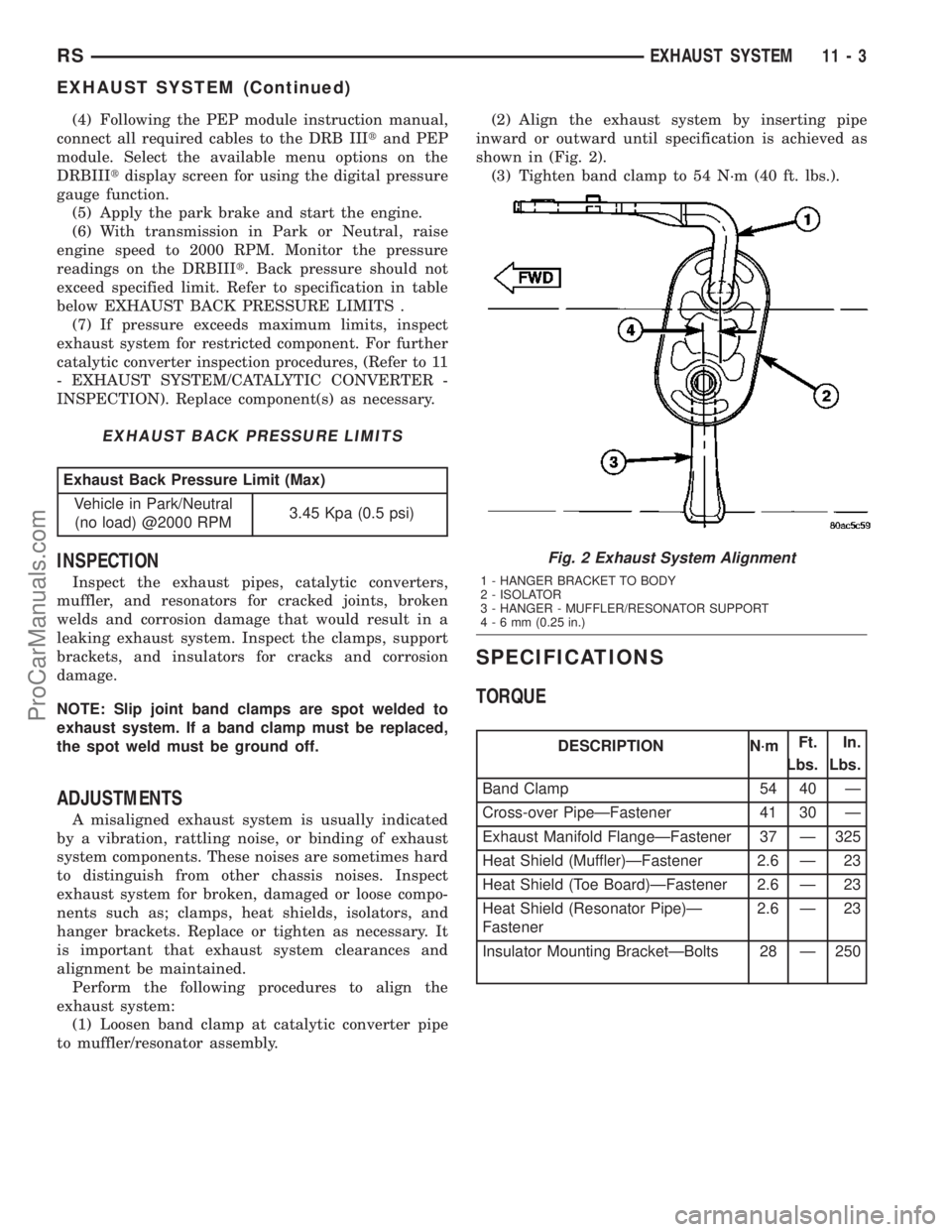
inward or outward until specification is achieved as
shown in (Fig. 2).
(3) Tighten band clamp to 54 N´m (40 ft. lbs.).
SPECIFICATIONS
TORQUE
DESCRIPTION N´mFt.
Lbs.In.
Lbs.
Band Clamp 54 40 Ð
Cross-over PipeÐFastener 41 30 Ð
Exhaust Manifold FlangeÐFastener 37 Ð 325
Heat Shield (Muffler)ÐFastener 2.6 Ð 23
Heat Shield (Toe Board)ÐFastener 2.6 Ð 23
Heat Shield (Resonator Pipe)Ð
Fastener2.6 Ð 23
Insulator Mounting BracketÐBolts 28 Ð 250
Fig. 2 Exhaust System Alignment
1 - HANGER BRACKET TO BODY
2 - ISOLATOR
3 - HANGER - MUFFLER/RESONATOR SUPPORT
4-6mm(0.25 in.)
RSEXHAUST SYSTEM11-3
EXHAUST SYSTEM (Continued)
ProCarManuals.com
Page 1356 of 2177

FRONT CRADLE
CROSSMEMBER
DESCRIPTION
DESCRIPTION - FRONT CRADLE
CROSSMEMBER
This vehicle uses a one piece cast aluminum cradle
for the front cradle crossmember. The cradle cross-
member is used as the attaching points for the lower
control arms, stabilizer bar and steering gear. The
cradle also has the power steering hoses and the
chassis brake tubes attached to it.
WARNING: If a threaded hole in the suspension cra-
dle needs to be repaired, only use the type of
thread insert and installation procedure specified
for this application.
The threaded holes in the front cradle crossmem-
ber that are used for attachment of the lower control
arm rear bushing retainer, power steering hose and
chassis brake tubes can be repaired. The repair is
done by the installation of a Heli-Coiltthread insert
which has been specifically developed for this appli-
cation. Refer to the Mopar Parts Catalog for the spec-
ified Heli-Coiltthread insert to be used for this
application. The procedure for installing the Heli-
Coiltthread insert is detailed in the Service Proce-
dures section in this group of the service manual.
DESCRIPTION - FRONT CRADLE
CROSSMEMBER THREAD REPAIR
WARNING: When performing this procedure use
only the thread inserts which are specified in the
Mopar Parts Catalog for this repair procedure.
These thread inserts have been specifically devel-
oped for this application and use of other types of
thread inserts can result in an inferior long term
repair.
The threaded holes in the front cradle crossmem-
ber, if damaged, can repaired by installing a Heli-
Coiltthread insert.
The threaded holes that are repairable using the
thread insert, are the lower control arm rear bushing
retainer mounting bolt holes, routing bracket attach-
ing locations for the power steering hoses, and brake
hose attachment holes.
This repair procedure now allows the threaded
holes in the cradle crossmember to be repaired, elim-
inating the need to replace the cradle crossmember if
damage occurs to one of the threaded holes.The thread inserts for this application are specified
by part number in the Mopar Parts Catalog.Do not
use a substitute thread insert.
The specific tools and equipment required to install
the thread insert are listed below. Refer to the
instructions included with the thread insert for the
detailed procedure used for the installation of the
thread insert.
NOTE: The thread inserts for this application are for
the repair of M8x1.25 and M10x1.5 threads. Be sure
the correct tools are used for the required thread
insert size.
TOOL REQUIREMENT FOR M8x1.25 Thread
²8.3mm (5/16 in.) Drill Bit
²120É Countersink
²Heli-CoiltTap #4863-8
²Heli-CoiltGage #4624-8
²Heli-CoiltHand Inserting Tool 7751-8
²Needle Nose Pliers ± For Removal Of Thread
Insert Driving Tang
TOOL REQUIREMENT FOR M10x1.5 Thread
²10.5mm (25/64 in.) Drill Bit
²120É Countersink
²Heli-CoiltTap #4863-10
²Heli-CoiltGage #4624-10
²Heli-CoiltHand Inserting Tool 7751-10
²Needle Nose Pliers ± For Removal Of Thread
Insert Driving Tang
REMOVAL
The front cradle crossmember must be installed in
the design location to achieve proper front end sus-
pension alignment. If the cradle crossmember is
removed without applying reference marks on the
frame rails, align the cradle crossmember according
to the dimensions provided in this group.
NOTE: If the caged nuts in the frame rails become
damaged and cannot be reused, a replacement nut
can be obtained through MoparT.
REMOVAL
(1) Disconnect battery negative cable.
(2) Remove steering column lower cover from
instrument panel (Refer to 23 - BODY/INSTRU-
MENT PANEL/STEERING COLUMN OPENING
COVER - REMOVAL).
(3) Remove steering column cover backing plate
(Refer to 23 - BODY/INSTRUMENT PANEL/STEER-
ING COLUMN COVER BACKING PLATE - REMOV-
AL).
RSFRAME & BUMPERS13-9
ProCarManuals.com
Page 1357 of 2177
(4) Position steering so front wheels are straight
ahead.
CAUTION: Do not rotate steering wheel after disen-
gaging lower coupling from steering gear, damage
to air bag clock spring can result.
(5) Remove clinch bolt attaching steering column
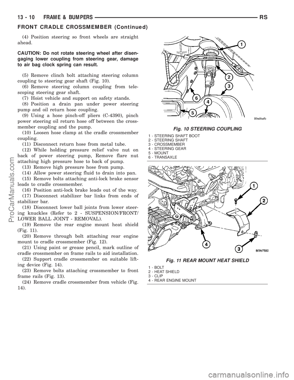
coupling to steering gear shaft (Fig. 10).
(6) Remove steering column coupling from tele-
scoping steering gear shaft.
(7) Hoist vehicle and support on safety stands.
(8) Position a drain pan under power steering
pump and oil return hose coupling.
(9) Using a hose pinch-off pliers (C-4390), pinch
power steering oil return hose off between the cross-
member coupling and the pump.
(10) Loosen hose clamp at the cradle crossmember
coupling.
(11) Disconnect return hose from metal tube.
(12) While holding pressure relief valve nut on
back of power steering pump, Remove flare nut
attaching high pressure hose to back of pump.
(13) Remove high pressure hose from pump.
(14) Allow power steering fluid to drain into pan.
(15) Remove bolts attaching anti-lock brake sensor
leads to cradle crossmember.
(16) Position anti-lock brake leads out of the way.
(17) Disconnect stabilizer bar links from ends of
stabilizer bar.
(18) Disconnect lower ball joints from lower steer-
ing knuckles (Refer to 2 - SUSPENSION/FRONT/
LOWER BALL JOINT - REMOVAL).
(19) Remove the rear engine mount heat shield
(Fig. 11).
(20) Remove through bolt attaching rear engine
mount to cradle crossmember (Fig. 12).
(21) Using paint or grease pencil, mark outline of
cradle crossmember on frame rails to aid installation.
(22) Support cradle crossmember on suitable lift-
ing device (Fig. 14).
(23) Remove bolts attaching crossmember to front
frame rails (Fig. 13).
(24) Remove cradle crossmember from vehicle (Fig.
14).
Fig. 10 STEERING COUPLING
1 - STEERING SHAFT BOOT
2 - STEERING SHAFT
3 - CROSSMEMBER
4 - STEERING GEAR
5 - MOUNT
6 - TRANSAXLE
Fig. 11 REAR MOUNT HEAT SHIELD
1 - BOLT
2 - HEAT SHIELD
3 - CLIP
4 - REAR ENGINE MOUNT
13 - 10 FRAME & BUMPERSRS
FRONT CRADLE CROSSMEMBER (Continued)
ProCarManuals.com
Page 1358 of 2177
INSTALLATION
NOTE: If cradle crossmember requires replacement.
Refer to Group 2, Suspension, to transfer suspen-
sion components and Group 19, Steering, to trans-
fer steering components.
(1) Support crossmember on suitable lifting device
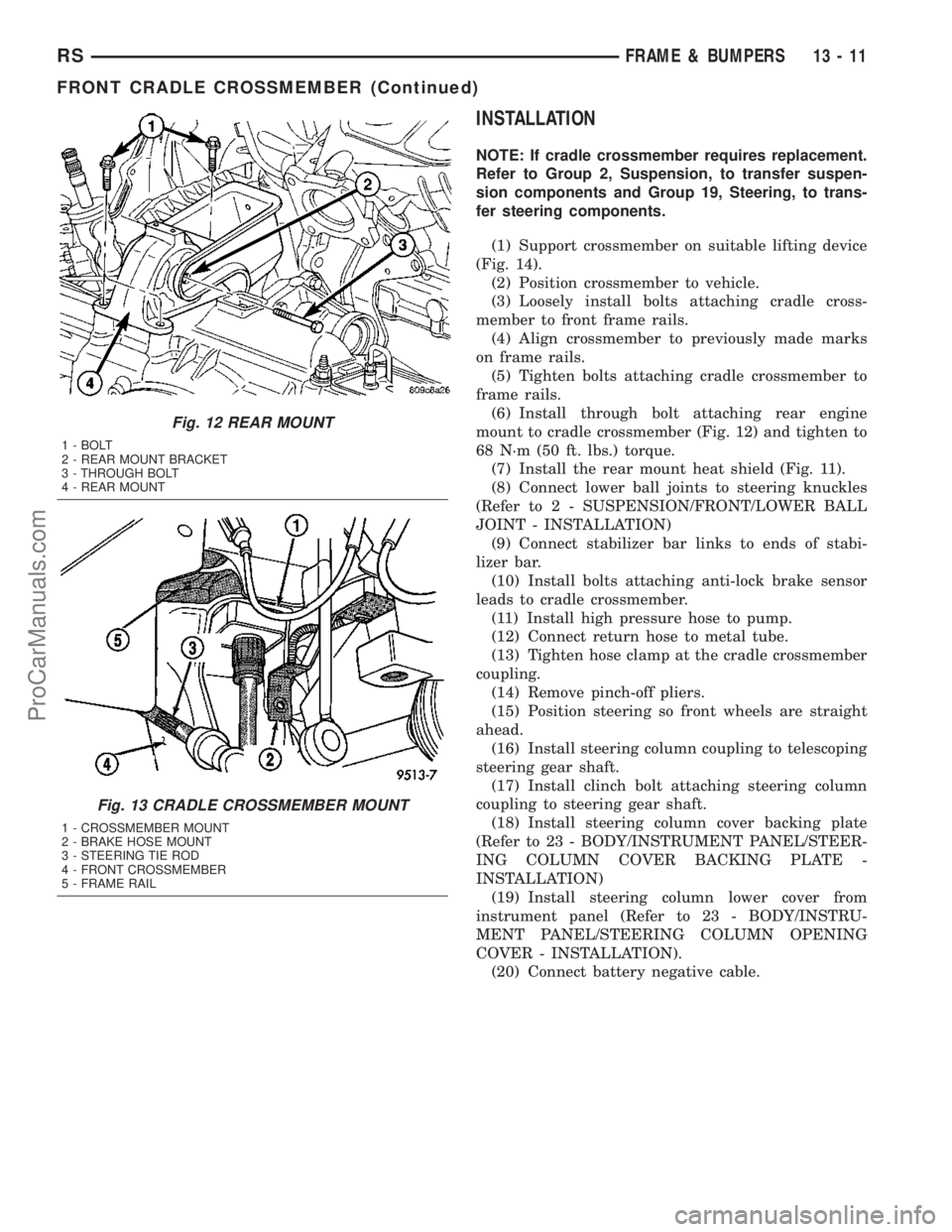
(Fig. 14).
(2) Position crossmember to vehicle.
(3) Loosely install bolts attaching cradle cross-
member to front frame rails.
(4) Align crossmember to previously made marks
on frame rails.
(5) Tighten bolts attaching cradle crossmember to
frame rails.
(6) Install through bolt attaching rear engine
mount to cradle crossmember (Fig. 12) and tighten to
68 N´m (50 ft. lbs.) torque.
(7) Install the rear mount heat shield (Fig. 11).
(8) Connect lower ball joints to steering knuckles
(Refer to 2 - SUSPENSION/FRONT/LOWER BALL
JOINT - INSTALLATION)
(9) Connect stabilizer bar links to ends of stabi-
lizer bar.
(10) Install bolts attaching anti-lock brake sensor
leads to cradle crossmember.
(11) Install high pressure hose to pump.
(12) Connect return hose to metal tube.
(13) Tighten hose clamp at the cradle crossmember
coupling.
(14) Remove pinch-off pliers.
(15) Position steering so front wheels are straight
ahead.
(16) Install steering column coupling to telescoping
steering gear shaft.
(17) Install clinch bolt attaching steering column
coupling to steering gear shaft.
(18) Install steering column cover backing plate
(Refer to 23 - BODY/INSTRUMENT PANEL/STEER-
ING COLUMN COVER BACKING PLATE -
INSTALLATION)
(19) Install steering column lower cover from
instrument panel (Refer to 23 - BODY/INSTRU-
MENT PANEL/STEERING COLUMN OPENING
COVER - INSTALLATION).
(20) Connect battery negative cable.
Fig. 12 REAR MOUNT
1 - BOLT
2 - REAR MOUNT BRACKET
3 - THROUGH BOLT
4 - REAR MOUNT
Fig. 13 CRADLE CROSSMEMBER MOUNT
1 - CROSSMEMBER MOUNT
2 - BRAKE HOSE MOUNT
3 - STEERING TIE ROD
4 - FRONT CROSSMEMBER
5 - FRAME RAIL
RSFRAME & BUMPERS13-11
FRONT CRADLE CROSSMEMBER (Continued)
ProCarManuals.com
Page 1387 of 2177
(2) Install injector clip by sliding open end into the
top slot of the injector. The edge of the receiver cup
will slide into the side slots of clip (Fig. 13).
(3) Install injector top end into fuel rail receiver
cap. Be careful not to damage O-ring during installa-
tion (Fig. 13).
(4) Repeat steps for remaining injectors.
(5) Install fuel rail, refer to Fuel Rail in the Fuel
Delivery section.
(6) Connect fuel injector wiring.
(7) Install the Intake Manifold, (Refer to 9 -
ENGINE/MANIFOLDS/INTAKE MANIFOLD -
INSTALLATION)
(8) Connect the negative battery cable.
FUEL PUMP RELAY
DESCRIPTION
The fuel pump relay is located in the PDC. The
inside top of the PDC cover has a label showing relay
and fuse location.
OPERATION
The fuel pump relay supplies battery voltage to the
fuel pump. A buss bar in the Power Distribution Cen-
ter (PDC) supplies voltage to the solenoid side and
contact side of the relay. The fuel pump relay power
circuit contains a fuse between the buss bar in the
PDC and the relay. The fuse is located in the PDC.
Refer to the Wiring Diagrams for circuit information.
The PCM controls the fuel pump relay by switch-
ing the ground path for the solenoid side of the relay
on and off. The PCM turns the ground path off when
the ignition switch is in the Off position. When the
ignition switch is in the On position, the PCM ener-
gizes the fuel pump. If the crankshaft position sensor
does not detect engine rotation, the PCM de-ener-
gizes the relay after approximately one second.
IDLE AIR CONTROL MOTOR
DESCRIPTION
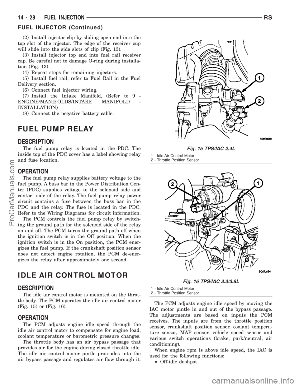
The idle air control motor is mounted on the throt-
tle body. The PCM operates the idle air control motor
(Fig. 15) or (Fig. 16).
OPERATION
The PCM adjusts engine idle speed through the
idle air control motor to compensate for engine load,
coolant temperature or barometric pressure changes.
The throttle body has an air bypass passage that
provides air for the engine during closed throttle idle.
The idle air control motor pintle protrudes into the
air bypass passage and regulates air flow through it.The PCM adjusts engine idle speed by moving the
IAC motor pintle in and out of the bypass passage.
The adjustments are based on inputs the PCM
receives. The inputs are from the throttle position
sensor, crankshaft position sensor, coolant tempera-
ture sensor, MAP sensor, vehicle speed sensor and
various switch operations (brake, park/neutral, air
conditioning).
When engine rpm is above idle speed, the IAC is
used for the following functions:
²Off-idle dashpot
Fig. 15 TPS/IAC 2.4L
1 - Idle Air Control Motor
2 - Throttle Position Sensor
Fig. 16 TPS/IAC 3.3/3.8L
1 - Idle Air Control Motor
2 - Throttle Position Sensor
14 - 28 FUEL INJECTIONRS
FUEL INJECTOR (Continued)
ProCarManuals.com
Page 1407 of 2177
WARNING: THE AIR BAG SYSTEM IS A SENSITIVE,
COMPLEX ELECTRO-MECHANICAL UNIT. BEFORE
ATTEMPTING TO DIAGNOSE, REMOVE OR INSTALL
THE AIR BAG SYSTEM COMPONENTS YOU MUST
FIRST DISCONNECT AND ISOLATE THE BATTERY
NEGATIVE (GROUND) CABLE. THEN WAIT TWO
MINUTES FOR THE SYSTEM CAPACITOR TO DIS-
CHARGE. FAILURE TO DO SO COULD RESULT IN
ACCIDENTAL DEPLOYMENT OF THE AIR BAG AND
POSSIBLE PERSONAL INJURY. THE FASTENERS,
SCREWS, AND BOLTS, ORIGINALLY USED FOR
THE AIR BAG COMPONENTS, HAVE SPECIAL
COATINGS AND ARE SPECIFICALLY DESIGNED
FOR THE AIR BAG SYSTEM. THEY MUST NEVER
BE REPLACED WITH ANY SUBSTITUTES. ANYTIME
A NEW FASTENER IS NEEDED, REPLACE WITH
THE CORRECT FASTENERS PROVIDED IN THE
SERVICE PACKAGE OR FASTENERS LISTED IN
THE PARTS BOOKS.
WARNING: SAFETY GOGGLES SHOULD BE WORN
AT ALL TIMES WHEN WORKING ON STEERING
COLUMNS.
CAUTION: Disconnect negative (ground) cable from
the battery before servicing any column compo-
nent.
CAUTION: Do not attempt to remove the pivot pins
to disassemble the tilting mechanism. Damage will
occur.
DIAGNOSIS AND TESTING - STEERING
COLUMN
For diagnosis of conditions relating to the steering
column (Refer to 19 - STEERING - DIAGNOSIS AND
TESTING) and (Refer to 19 - STEERING - DIAGNO-
SIS AND TESTING).
REMOVAL
NOTE: Before proceeding, (Refer to 19 - STEERING/
COLUMN - WARNING).
(1) Make sure the front wheels of the vehicle are
in the STRAIGHT AHEAD position before beginning
the column removal procedure.
(2) Disconnect negative (ground) cable from the
battery and isolate cable from battery terminal.
(3) Remove the lower shroud (Refer to 19 -
STEERING/COLUMN/LOWER SHROUD - REMOV-
AL).
(4) Remove the traction off switch.
(5) Remove the upper shroud.
(6) Remove the cluster trim bezel (Refer to 23 -
BODY/INSTRUMENT PANEL/CLUSTER BEZEL -
REMOVAL).
(7) Remove the knee blocker (Refer to 23 - BODY/
INSTRUMENT PANEL/STEERING COLUMN
OPENING COVER - REMOVAL).
(8) Remove the parking brake handle link.
(9) Remove the knee blocker reinforcement (Refer
to 23 - BODY/INSTRUMENT PANEL/KNEE
BLOCKER - REMOVAL).
(10) Remove the airbag (Refer to 8 - ELECTRI-
CAL/RESTRAINTS/DRIVER AIRBAG - REMOVAL).
(11) Remove the steering wheel retaining nut.
(12) Remove the vibration damper weight.
(13) Remove the steering wheel (Refer to 19 -
STEERING/COLUMN/STEERING WHEEL -
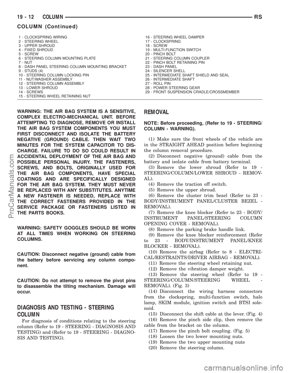
REMOVAL). (Fig. 3)
(14) Disconnect the wiring harness connectors
from the clockspring, multi-function switch, halo
lamp, SKIM module, ignition switch and BTSI sole-
noid.
(15) Disconnect the shift cable at the lever. (Fig. 4)
(16) Remove the pinch side clip, then remove the
cable from the bracket on the column.
(17) Remove the pinch bolt coupling. (Fig. 5)
(18) Loosen the two lower mounting nuts.
(19) Remove the two upper mounting nuts
(20) Remove the steering column.
1 - CLOCKSPRING WIRING
2 - STEERING WHEEL
3 - UPPER SHROUD
4 - FIXED SHROUD
5 - SCREW
6 - STEERING COLUMN MOUNTING PLATE
7 - NUT
8 - DASH PANEL STEERING COLUMN MOUNTING BRACKET
9 - STUDS (4)
10 - STEERING COLUMN LOCKING PIN
11 - NUT/WASHER ASSEMBLY
12 - STEERING COLUMN ASSEMBLY
13 - LOWER SHROUD
14 - SCREWS
15 - STEERING WHEEL RETAINING NUT16 - STEERING WHEEL DAMPER
17 - CLOCKSPRING
18 - SCREW
19 - MULTI-FUNCTION SWITCH
20 - PINCH BOLT
21 - STEERING COLUMN COUPLER
22 - PINCH BOLT RETAINING PIN
23 - DASH PANEL
24 - SILENCER SHELL
25 - INTERMEDIATE SHAFT SHIELD AND SEAL
26 - INTERMEDIATE SHAFT
27 - ROLL PIN
28 - POWER STEERING GEAR
29 - FRONT SUSPENSION CRADLE/CROSSMEMBER
19 - 12 COLUMNRS
COLUMN (Continued)
ProCarManuals.com
Page 1409 of 2177
(10) Install the coupling onto the intermediate
shaft and install the pinch bolt. Tighten the pinch
bolt to 28 N´m (250 in. lbs.).
(11) Install the cable from the bracket on the col-
umn, then install the pinch side clips.
(12) Reconnect the shift cable at the lever.
(13) Reconnect the wiring harness connectors to
the clockspring, multi-function switch, halo lamp,
SKIM module, ignition switch and BTSI solenoid.
(14) Install the steering wheel (Refer to 19 -
STEERING/COLUMN/STEERING WHEEL -
INSTALLATION).
(15) Install the vibration damper weight.
(16) Install the steering wheel retaining nut.
Tighten the nut to 61 N´m (45 ft. lbs.)
(17) Install the airbag (Refer to 8 - ELECTRICAL/
RESTRAINTS/DRIVER AIRBAG - INSTALLATION).
(18) Install the knee blocker reinforcement (Refer
to 23 - BODY/INSTRUMENT PANEL/KNEE
BLOCKER - INSTALLATION).
(19) Install the parking brake handle link.
(20) Install the knee blocker (Refer to 23 - BODY/
INSTRUMENT PANEL/STEERING COLUMN
OPENING COVER - INSTALLATION).
(21) Install the cluster trim bezel (Refer to 23 -
BODY/INSTRUMENT PANEL/CLUSTER BEZEL -
INSTALLATION).
(22) Install the upper shroud (Refer to 19 -
STEERING/COLUMN/LOWER SHROUD - INSTAL-
LATION).
(23) Install the traction off switch.
(24) Install the lower shroud.
SPECIFICATIONS
COLUMN TORQUE
DESCRIPTION N´mFt.
Lbs.In.
Lbs.
Driver Airbag Attaching Bolts 10 Ð 90
Steering Column Coupling
Pinch Bolt28 Ð 250
Steering Column Mounting
Nuts12 Ð 105
Steering Wheel Retaining
Nut61 45 Ð
IGNITION SWITCH
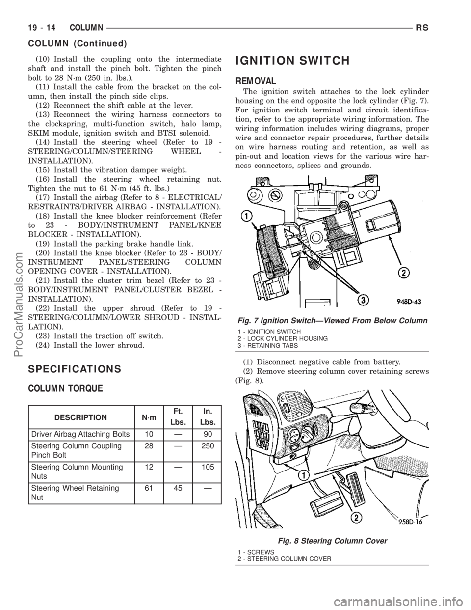
REMOVAL
The ignition switch attaches to the lock cylinder
housing on the end opposite the lock cylinder (Fig. 7).
For ignition switch terminal and circuit identifica-
tion, refer to the appropriate wiring information. The
wiring information includes wiring diagrams, proper
wire and connector repair procedures, further details
on wire harness routing and retention, as well as
pin-out and location views for the various wire har-
ness connectors, splices and grounds.
(1) Disconnect negative cable from battery.
(2) Remove steering column cover retaining screws
(Fig. 8).
Fig. 7 Ignition SwitchÐViewed From Below Column
1 - IGNITION SWITCH
2 - LOCK CYLINDER HOUSING
3 - RETAINING TABS
Fig. 8 Steering Column Cover
1 - SCREWS
2 - STEERING COLUMN COVER
19 - 14 COLUMNRS
COLUMN (Continued)
ProCarManuals.com