2003 CHRYSLER CARAVAN brake
[x] Cancel search: brakePage 1118 of 2177
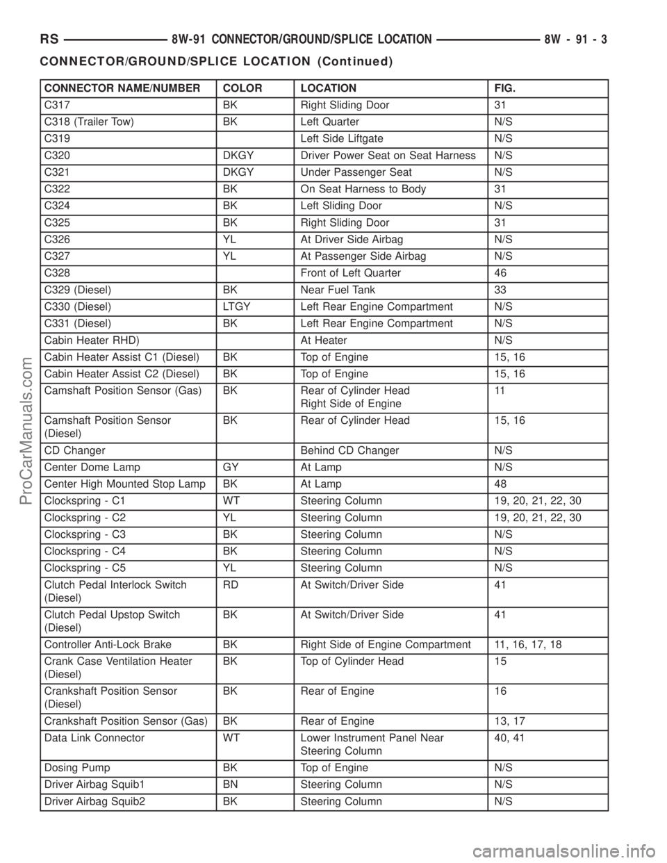
CONNECTOR NAME/NUMBER COLOR LOCATION FIG.
C317 BK Right Sliding Door 31
C318 (Trailer Tow) BK Left Quarter N/S
C319 Left Side Liftgate N/S
C320 DKGY Driver Power Seat on Seat Harness N/S
C321 DKGY Under Passenger Seat N/S
C322 BK On Seat Harness to Body 31
C324 BK Left Sliding Door N/S
C325 BK Right Sliding Door 31
C326 YL At Driver Side Airbag N/S
C327 YL At Passenger Side Airbag N/S
C328 Front of Left Quarter 46
C329 (Diesel) BK Near Fuel Tank 33
C330 (Diesel) LTGY Left Rear Engine Compartment N/S
C331 (Diesel) BK Left Rear Engine Compartment N/S
Cabin Heater RHD) At Heater N/S
Cabin Heater Assist C1 (Diesel) BK Top of Engine 15, 16
Cabin Heater Assist C2 (Diesel) BK Top of Engine 15, 16
Camshaft Position Sensor (Gas) BK Rear of Cylinder Head
Right Side of Engine11
Camshaft Position Sensor
(Diesel)BK Rear of Cylinder Head 15, 16
CD Changer Behind CD Changer N/S
Center Dome Lamp GY At Lamp N/S
Center High Mounted Stop Lamp BK At Lamp 48
Clockspring - C1 WT Steering Column 19, 20, 21, 22, 30
Clockspring - C2 YL Steering Column 19, 20, 21, 22, 30
Clockspring - C3 BK Steering Column N/S
Clockspring - C4 BK Steering Column N/S
Clockspring - C5 YL Steering Column N/S
Clutch Pedal Interlock Switch
(Diesel)RD At Switch/Driver Side 41
Clutch Pedal Upstop Switch
(Diesel)BK At Switch/Driver Side 41
Controller Anti-Lock Brake BK Right Side of Engine Compartment 11, 16, 17, 18
Crank Case Ventilation Heater
(Diesel)BK Top of Cylinder Head 15
Crankshaft Position Sensor
(Diesel)BK Rear of Engine 16
Crankshaft Position Sensor (Gas) BK Rear of Engine 13, 17
Data Link Connector WT Lower Instrument Panel Near
Steering Column40, 41
Dosing Pump BK Top of Engine N/S
Driver Airbag Squib1 BN Steering Column N/S
Driver Airbag Squib2 BK Steering Column N/S
RS8W-91 CONNECTOR/GROUND/SPLICE LOCATION8W-91-3
CONNECTOR/GROUND/SPLICE LOCATION (Continued)
ProCarManuals.com
Page 1126 of 2177
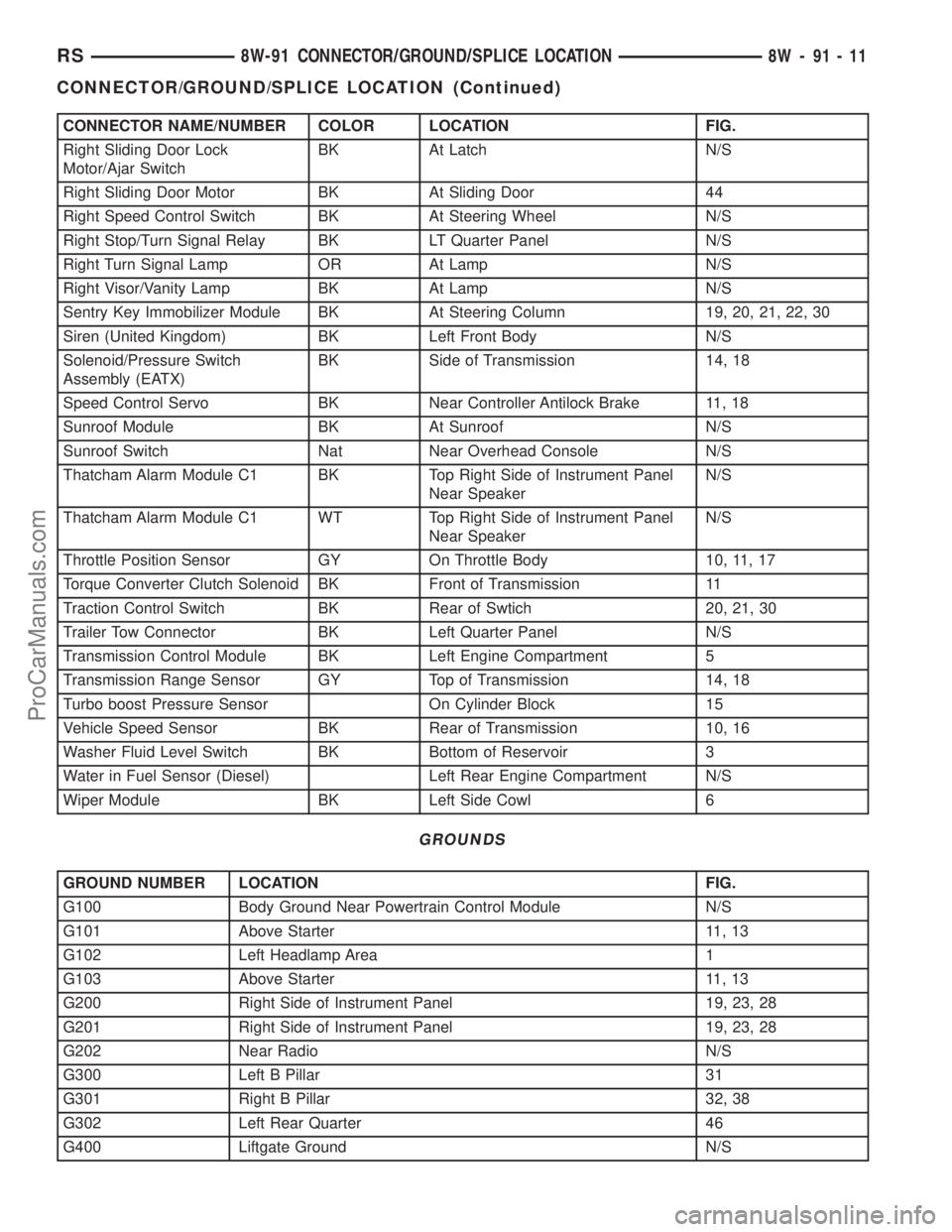
CONNECTOR NAME/NUMBER COLOR LOCATION FIG.
Right Sliding Door Lock
Motor/Ajar SwitchBK At Latch N/S
Right Sliding Door Motor BK At Sliding Door 44
Right Speed Control Switch BK At Steering Wheel N/S
Right Stop/Turn Signal Relay BK LT Quarter Panel N/S
Right Turn Signal Lamp OR At Lamp N/S
Right Visor/Vanity Lamp BK At Lamp N/S
Sentry Key Immobilizer Module BK At Steering Column 19, 20, 21, 22, 30
Siren (United Kingdom) BK Left Front Body N/S
Solenoid/Pressure Switch
Assembly (EATX)BK Side of Transmission 14, 18
Speed Control Servo BK Near Controller Antilock Brake 11, 18
Sunroof Module BK At Sunroof N/S
Sunroof Switch Nat Near Overhead Console N/S
Thatcham Alarm Module C1 BK Top Right Side of Instrument Panel
Near SpeakerN/S
Thatcham Alarm Module C1 WT Top Right Side of Instrument Panel
Near SpeakerN/S
Throttle Position Sensor GY On Throttle Body 10, 11, 17
Torque Converter Clutch Solenoid BK Front of Transmission 11
Traction Control Switch BK Rear of Swtich 20, 21, 30
Trailer Tow Connector BK Left Quarter Panel N/S
Transmission Control Module BK Left Engine Compartment 5
Transmission Range Sensor GY Top of Transmission 14, 18
Turbo boost Pressure Sensor On Cylinder Block 15
Vehicle Speed Sensor BK Rear of Transmission 10, 16
Washer Fluid Level Switch BK Bottom of Reservoir 3
Water in Fuel Sensor (Diesel) Left Rear Engine Compartment N/S
Wiper Module BK Left Side Cowl 6
GROUNDS
GROUND NUMBER LOCATION FIG.
G100 Body Ground Near Powertrain Control Module N/S
G101 Above Starter 11, 13
G102 Left Headlamp Area 1
G103 Above Starter 11, 13
G200 Right Side of Instrument Panel 19, 23, 28
G201 Right Side of Instrument Panel 19, 23, 28
G202 Near Radio N/S
G300 Left B Pillar 31
G301 Right B Pillar 32, 38
G302 Left Rear Quarter 46
G400 Liftgate Ground N/S
RS8W-91 CONNECTOR/GROUND/SPLICE LOCATION8W-91-11
CONNECTOR/GROUND/SPLICE LOCATION (Continued)
ProCarManuals.com
Page 1237 of 2177
INTAKE MANIFOLD
DESCRIPTION
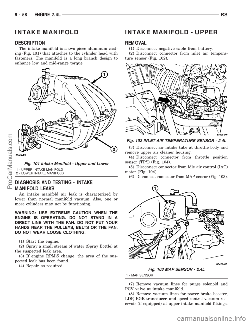
The intake manifold is a two piece aluminum cast-
ing (Fig. 101) that attaches to the cylinder head with
fasteners. The manifold is a long branch design to
enhance low and mid-range torque
DIAGNOSIS AND TESTING - INTAKE
MANIFOLD LEAKS
An intake manifold air leak is characterized by
lower than normal manifold vacuum. Also, one or
more cylinders may not be functioning.
WARNING: USE EXTREME CAUTION WHEN THE
ENGINE IS OPERATING. DO NOT STAND IN A
DIRECT LINE WITH THE FAN. DO NOT PUT YOUR
HANDS NEAR THE PULLEYS, BELTS OR THE FAN.
DO NOT WEAR LOOSE CLOTHING.
(1) Start the engine.
(2) Spray a small stream of water (Spray Bottle) at
the suspected leak area.
(3) If engine RPM'S change, the area of the sus-
pected leak has been found.
(4) Repair as required.
INTAKE MANIFOLD - UPPER
REMOVAL
(1) Disconnect negative cable from battery.
(2) Disconnect connector from inlet air tempera-
ture sensor (Fig. 102).
(3) Disconnect air intake tube at throttle body and
remove upper air cleaner housing.
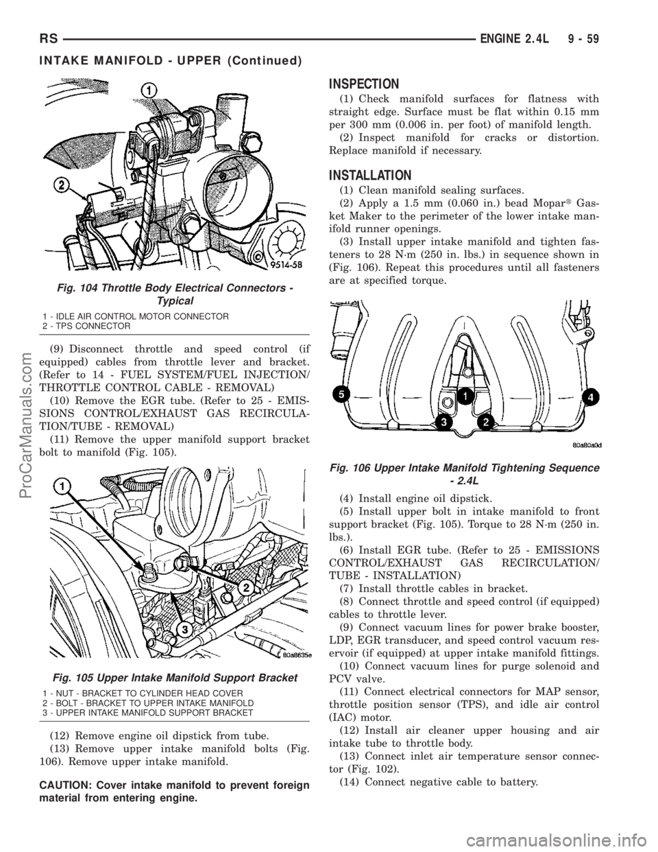
(4) Disconnect connector from throttle position
sensor (TPS) (Fig. 104).
(5) Disconnect connector from idle air control (IAC)
motor (Fig. 104).
(6)
Disconnect connector from MAP sensor (Fig. 103).
(7) Remove vacuum lines for purge solenoid and
PCV valve at intake manifold.
(8) Remove vacuum lines for power brake booster,
LDP, EGR transducer, and speed control vacuum res-
ervoir (if equipped) at upper intake manifold fittings.
Fig. 101 Intake Manifold - Upper and Lower
1 - UPPER INTAKE MANIFOLD
2 - LOWER INTAKE MANIFOLD
Fig. 102 INLET AIR TEMPERATURE SENSOR - 2.4L
Fig. 103 MAP SENSOR - 2.4L
1 - MAP SENSOR
9 - 58 ENGINE 2.4LRS
ProCarManuals.com
Page 1238 of 2177
(9) Disconnect throttle and speed control (if
equipped) cables from throttle lever and bracket.
(Refer to 14 - FUEL SYSTEM/FUEL INJECTION/
THROTTLE CONTROL CABLE - REMOVAL)
(10) Remove the EGR tube. (Refer to 25 - EMIS-
SIONS CONTROL/EXHAUST GAS RECIRCULA-
TION/TUBE - REMOVAL)
(11) Remove the upper manifold support bracket
bolt to manifold (Fig. 105).
(12) Remove engine oil dipstick from tube.
(13) Remove upper intake manifold bolts (Fig.
106). Remove upper intake manifold.
CAUTION: Cover intake manifold to prevent foreign
material from entering engine.
INSPECTION
(1) Check manifold surfaces for flatness with
straight edge. Surface must be flat within 0.15 mm
per 300 mm (0.006 in. per foot) of manifold length.
(2) Inspect manifold for cracks or distortion.
Replace manifold if necessary.
INSTALLATION
(1) Clean manifold sealing surfaces.
(2) Apply a 1.5 mm (0.060 in.) bead MopartGas-
ket Maker to the perimeter of the lower intake man-
ifold runner openings.
(3) Install upper intake manifold and tighten fas-
teners to 28 N´m (250 in. lbs.) in sequence shown in
(Fig. 106). Repeat this procedures until all fasteners
are at specified torque.
(4) Install engine oil dipstick.
(5) Install upper bolt in intake manifold to front
support bracket (Fig. 105). Torque to 28 N´m (250 in.
lbs.).
(6) Install EGR tube. (Refer to 25 - EMISSIONS
CONTROL/EXHAUST GAS RECIRCULATION/
TUBE - INSTALLATION)
(7) Install throttle cables in bracket.
(8) Connect throttle and speed control (if equipped)
cables to throttle lever.
(9) Connect vacuum lines for power brake booster,
LDP, EGR transducer, and speed control vacuum res-
ervoir (if equipped) at upper intake manifold fittings.
(10) Connect vacuum lines for purge solenoid and
PCV valve.
(11) Connect electrical connectors for MAP sensor,
throttle position sensor (TPS), and idle air control
(IAC) motor.
(12) Install air cleaner upper housing and air
intake tube to throttle body.
(13) Connect inlet air temperature sensor connec-
tor (Fig. 102).
(14) Connect negative cable to battery.
Fig. 104 Throttle Body Electrical Connectors -
Typical
1 - IDLE AIR CONTROL MOTOR CONNECTOR
2 - TPS CONNECTOR
Fig. 105 Upper Intake Manifold Support Bracket
1 - NUT - BRACKET TO CYLINDER HEAD COVER
2 - BOLT - BRACKET TO UPPER INTAKE MANIFOLD
3 - UPPER INTAKE MANIFOLD SUPPORT BRACKET
Fig. 106 Upper Intake Manifold Tightening Sequence
- 2.4L
RSENGINE 2.4L9-59
INTAKE MANIFOLD - UPPER (Continued)
ProCarManuals.com
Page 1266 of 2177
(11) Disconnect the throttle cables from the throt-
tle body.
(12) Disconnect the MAP, IAC, and TPS electrical
connectors.
(13) Disconnect the EGR transducer electrical con-
nector (if equipped).
(14) Disconnect the vacuum hoses from throttle
body.
(15) Disconnect the brake booster and speed con-
trol vacuum hoses.
(16) Disengage wire harness clip from the right
side engine mount.
(17) Remove the power steering reservoir from
mounting position and set aside.Do notdisconnect
hose.
(18) Disconnect ground strap from rear of cylinder
head.
(19) Disconnect engine coolant temperature (ECT)
sensor and ignition coil electrical connectors.
(20) Disconnect the fuel injector electrical harness
connector and disengage clip from support bracket.
(21) Disconnect camshaft and crankshaft position
sensor electrical connectors.
(22) Evacuate air conditioning system. Refer to 24
- HEATING & AIR CONDITIONING.
(23) Disconnect A/C compressor electrical connec-
tor.
(24) Disconnect the A/C lines from compressor.
Cover and seal all openings of hoses and compressor.
(25) Remove the radiator upper hose.
(26) Disengage electrical harness clip at transaxle
dipstick tube.
(27) Remove transaxle dipstick tube. Seal opening
using a suitable plug.
NOTE: When the transaxle cooler lines are removed
from the rolled-groove type fittings at the transaxle,
damage to the inner wall of the hose will occur. To
prevent prevent potential leakage, the cooler hoses
must be cut off flush at the transaxle fitting, and a
service cooler hose splice kit must be installed
upon reassembly.
(28) Using a blade or suitable hose cutter, cut
transaxle oil cooler lines off flush with fittings. Plug
cooler lines and fittings to prevent debris from enter-
ing transaxle or cooler circuit. A service splice kit will
be installed upon reassembly.
(29) Disconnect transaxle shift linkage and electri-
cal connectors.
(30)
Raise vehicle on hoist and drain the engine oil.
(31) Remove the axle shafts. (Refer to 3 - DIFFER-
ENTIAL & DRIVELINE/HALF SHAFT - REMOVAL)
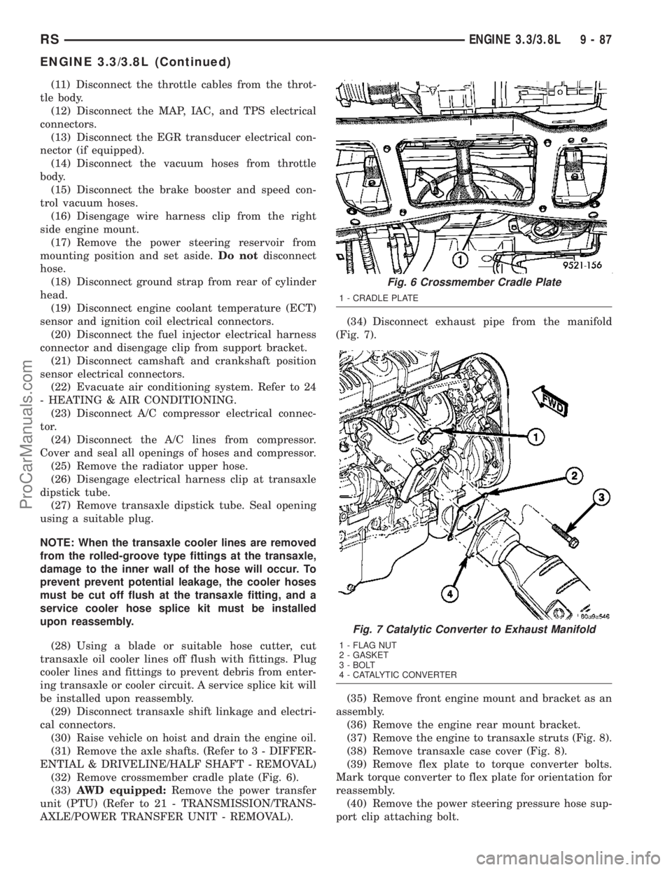
(32) Remove crossmember cradle plate (Fig. 6).
(33)AWD equipped:Remove the power transfer
unit (PTU) (Refer to 21 - TRANSMISSION/TRANS-
AXLE/POWER TRANSFER UNIT - REMOVAL).(34) Disconnect exhaust pipe from the manifold
(Fig. 7).
(35) Remove front engine mount and bracket as an
assembly.
(36) Remove the engine rear mount bracket.
(37) Remove the engine to transaxle struts (Fig. 8).
(38) Remove transaxle case cover (Fig. 8).
(39) Remove flex plate to torque converter bolts.
Mark torque converter to flex plate for orientation for
reassembly.
(40) Remove the power steering pressure hose sup-
port clip attaching bolt.
Fig. 6 Crossmember Cradle Plate
1 - CRADLE PLATE
Fig. 7 Catalytic Converter to Exhaust Manifold
1 - FLAG NUT
2 - GASKET
3 - BOLT
4 - CATALYTIC CONVERTER
RSENGINE 3.3/3.8L9-87
ENGINE 3.3/3.8L (Continued)
ProCarManuals.com
Page 1269 of 2177
(8) Install the generator and wiring harness (Refer
to 8 - ELECTRICAL/CHARGING/GENERATOR -
INSTALLATION).
(9) Raise vehicle.
(10) Attach wiring harness support clip to the
engine oil dipstick tube.
(11) Connect oil pressure switch electrical connec-
tor.
(12) Install the A/C compressor.
(13) Install the water pump pulley.
(14) Connect the radiator lower hose.(15) Install the accessory drive belt and splash
shield (Refer to 7 - COOLING/ACCESSORY DRIVE/
DRIVE BELTS - INSTALLATION).
(16) Connect the engine block heater electrical con-
nector (if equipped).
(17) Connect the knock sensor electrical connector
(3.8L only).
(18) Install the torque converter to flex plate bolts.
(19) Install the transaxle case cover (Fig. 8).
(20) Install the powertrain struts (Fig. 8).
(21) Install the engine rear mount bracket.
(22) Install the engine front mount and bracket
assembly.
(23)AWD equipped;Install the power transfer
unit (PTU) (Refer to 21 - TRANSMISSION/TRANS-
AXLE/POWER TRANSFER UNIT - INSTALLA-
TION).
(24) Install the axle shafts (Refer to 3 - DIFFER-
ENTIAL & DRIVELINE/HALF SHAFT - INSTALLA-
TION).
(25) Connect exhaust pipe to manifold (Fig. 7).
(26) Install crossmember cradle plate (Fig. 6).
(27) Lower vehicle.
(28) Connect transaxle shift linkage.
(29) Connect transaxle electrical connectors.
(30) Remove plugs from transmission cooler hoses
and install transaxle oil cooler line service splice kit.
Refer to instructions included with kit.
(31) Install transaxle dipstick tube and attach
electrical harness clip.
(32) Connect the A/C lines to compressor.
(33) Connect the A/C compressor electrical connec-
tor.
(34) Evacuate and recharge A/C system.
(35) Connect crankshaft and camshaft position
sensors.
(36) Connect the fuel injector electrical harness
connector and engage clip to support bracket.
(37) Connect engine coolant temperature (ECT)
sensor and ignition coil electrical connectors.
(38) Connect the ground strap to rear of cylinder
head.
(39) Install power steering reservoir.
(40) Engage wire harness clip to engine right side
mount.
(41) Connect the brake booster and speed control
vacuum hoses.
(42) Connect the vacuum hoses to the throttle
body.
(43) Connect the EGR transducer electrical connec-
tor (if equipped).
(44) Connect the TPS, IAC, and MAP sensor elec-
trical connectors.
(45) Connect throttle cables to throttle body.
(46) Install the radiator fans (Refer to 7 - COOL-
ING/ENGINE/RADIATOR FAN - INSTALLATION).
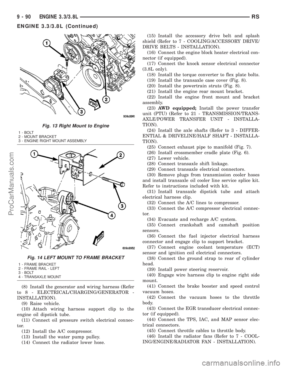
Fig. 13 Right Mount to Engine
1 - BOLT
2 - MOUNT BRACKET
3 - ENGINE RIGHT MOUNT ASSEMBLY
Fig. 14 LEFT MOUNT TO FRAME BRACKET
1 - FRAME BRACKET
2 - FRAME RAIL - LEFT
3 - BOLT
4 - TRANSAXLE MOUNT
9 - 90 ENGINE 3.3/3.8LRS
ENGINE 3.3/3.8L (Continued)
ProCarManuals.com
Page 1324 of 2177
DIAGNOSIS AND TESTING - INTAKE
MANIFOLD LEAKS
An intake manifold air leak is characterized by
lower than normal manifold vacuum. Also, one or
more cylinders may not be functioning.
WARNING: USE EXTREME CAUTION WHEN THE
ENGINE IS OPERATING. DO NOT STAND IN A
DIRECT LINE WITH THE FAN. DO NOT PUT YOUR
HANDS NEAR THE PULLEYS, BELTS OR THE FAN.
DO NOT WEAR LOOSE CLOTHING.
(1) Start the engine.
(2) Spray a small stream of water (Spray Bottle) at
the suspected leak area.
(3) If engine RPM'S change, the area of the sus-
pected leak has been found.
(4) Repair as required.
INTAKE MANIFOLD - UPPER
STANDARD PROCEDURE
STANDARD PROCEDURE - MANIFOLD
STRIPPED THREAD REPAIR
The composite upper intake manifold thread
bosses, if stripped out, can be repaired by utilizing a
repair screw available through Mopartparts. Repair
screws are available for the following manifold
attached components:
²MAP sensor
²Power steering reservoir
²EGR tube
²Throttle cable bracket
The repair screws require a unique tightening
torque specification from the original screw. Refer to
the following chart for specification.
DESCRIPTION TORQUE*
STRIP-OUT REPAIR SCREWS ONLY
MAP Sensor Repair
Screw4 N´m (35 in. lbs.)
Power Steering Reservoir
Repair Screw9 N´m (80 in. lbs.)
EGR Tube Attaching
Repair Screw9 N´m (80 in. lbs.)
Throttle Cable Bracket
Repair Screw9 N´m (80 in. lbs.)
*Install Slowly Using Hand Tools Only
STANDARD PROCEDURE - INTAKE MANIFOLD
VACUUM PORT REPAIR
The composite intake manifold vacuum ports can
be repaired. Although, if the manifold plenum cham-
ber is damaged or cracked, the manifold must be
replaced.
To repair a broken or damaged vacuum nipple
(port) on the composite intake manifold, perform the
following procedure:
PARTS REQUIRED TOOLS REQUIRED
´ Brass Nipple ± 1/49
O.D. x 1/89pipe thread
(LDP/Speed Control Port)´ Pipe Tap ± 1/89-18
NPT
´ Drill Bit ± 11/329
´ File/Sandpaper
´ Brass Nipple ± 1/29
O.D. x 1/49pipe thread
(Brake Booster Port)´ Pipe Tap ± 1/49-18
NPT
´ Drill Bit ± 7/169
´ File/Sandpaper
NOTE: While performing this procedure, avoid get-
ting the manifold material residue into the plenum
chamber.
(1) File or sand the remaining port back until a
flat surface is obtained (plane normal to nipple (port)
axis).
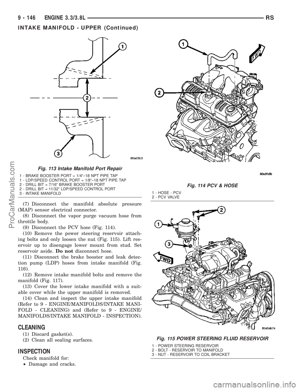
(2) Drill out the nipple (port) base using a 7/16º
(brake booster port) or 11/32º (LDP/speed control port
) drill bit (Fig. 113).
(3) Using a 1/4º±18 NPT (brake booster port) or
1/8º±18 NPT (LDP/speed control port ) pipe tap, cut
internal threads (Fig. 113). Use caution to start tap
in a axis same as original nipple.
(4) Apply MopartThread Sealant to threads of
repair nipple(s).
(5) Install repair nipple(s). Do not over torque
repair nipple(s).
REMOVAL - UPPER INTAKE MANIFOLD
(1) Disconnect battery negative cable.
(2) Disconnect inlet air temperature (IAT) sensor
electrical connector.
(3) Remove air inlet resonator to throttle body
hose assembly.
(4) Disconnect throttle and speed control cables
from throttle body (Refer to 14 - FUEL SYSTEM/
FUEL INJECTION/THROTTLE CONTROL CABLE -
REMOVAL).
(5) Disconnect make-up air hose support clip from
throttle cable bracket.
(6) Disconnect the automatic idle speed (AIS)
motor and throttle position sensor (TPS) wiring con-
nectors from throttle body.
RSENGINE 3.3/3.8L9 - 145
INTAKE MANIFOLD (Continued)
ProCarManuals.com
Page 1325 of 2177
(7) Disconnect the manifold absolute pressure
(MAP) sensor electrical connector.
(8) Disconnect the vapor purge vacuum hose from
throttle body.
(9) Disconnect the PCV hose (Fig. 114).
(10) Remove the power steering reservoir attach-
ing bolts and only loosen the nut (Fig. 115). Lift res-
ervoir up to disengage lower mount from stud. Set
reservoir aside.Do notdisconnect hose.
(11) Disconnect the brake booster and leak detec-
tion pump (LDP) hoses from intake manifold (Fig.
116).
(12) Remove intake manifold bolts and remove the
manifold (Fig. 117).
(13) Cover the lower intake manifold with a suit-
able cover while the upper manifold is removed.
(14) Clean and inspect the upper intake manifold
(Refer to 9 - ENGINE/MANIFOLDS/INTAKE MANI-
FOLD - CLEANING) and (Refer to 9 - ENGINE/
MANIFOLDS/INTAKE MANIFOLD - INSPECTION).
CLEANING
(1) Discard gasket(s).
(2) Clean all sealing surfaces.
INSPECTION
Check manifold for:
²Damage and cracks.
Fig. 113 Intake Manifold Port Repair
1 - BRAKE BOOSTER PORT = 1/49±18 NPT PIPE TAP
1 - LDP/SPEED CONTROL PORT = 1/89±18 NPT PIPE TAP
2 - DRILL BIT = 7/169BRAKE BOOSTER PORT
2 - DRILL BIT = 11/329LDP/SPEED CONTROL PORT
3 - INTAKE MANIFOLD
Fig. 114 PCV & HOSE
1 - HOSE - PCV
2 - P C V VA LV E
Fig. 115 POWER STEERING FLUID RESERVOIR
1 - POWER STEERING RESERVOIR
2 - BOLT - RESERVOIR TO MANIFOLD
3 - NUT - RESERVOIR TO COIL BRACKET
9 - 146 ENGINE 3.3/3.8LRS
INTAKE MANIFOLD - UPPER (Continued)
ProCarManuals.com