2003 CHRYSLER CARAVAN steering
[x] Cancel search: steeringPage 1731 of 2177
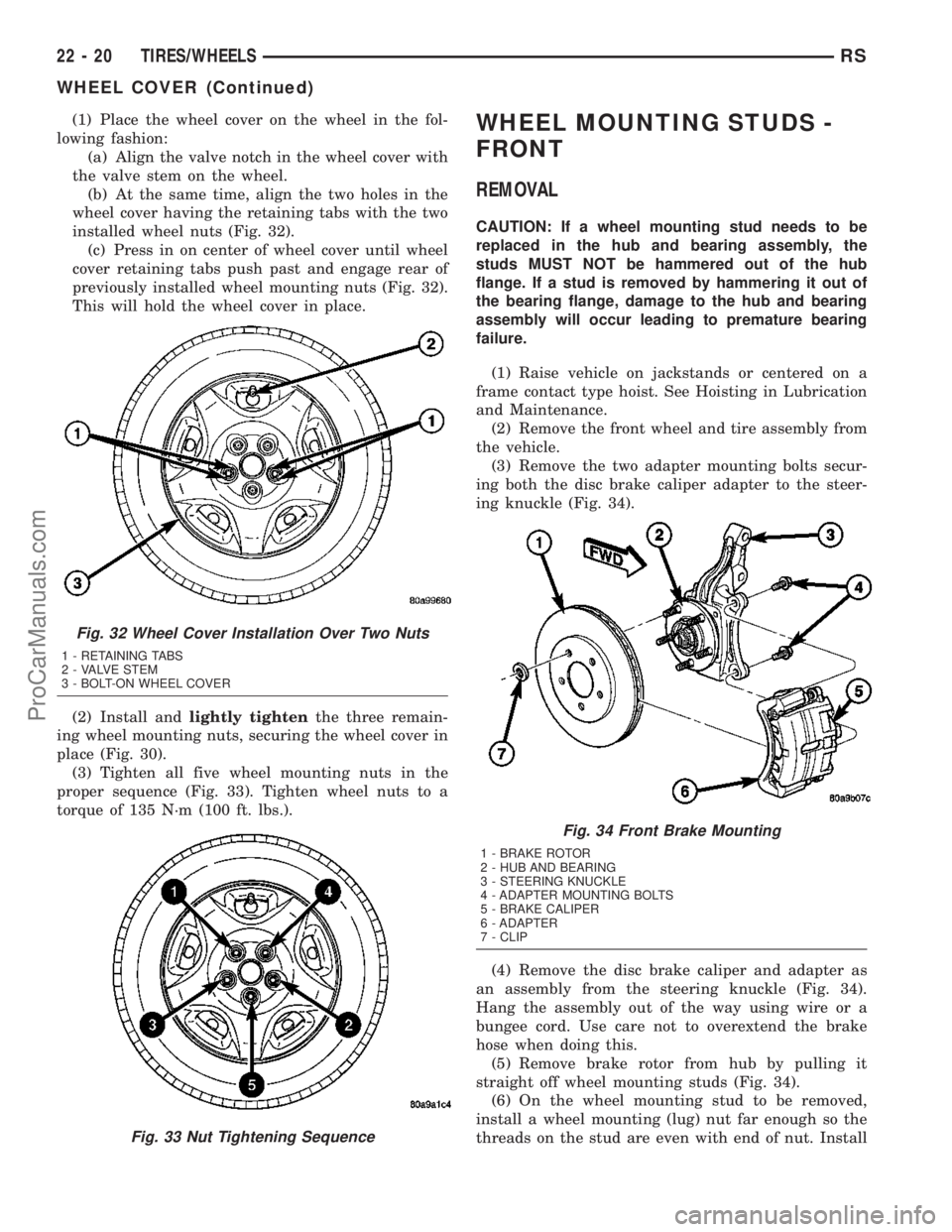
(1) Place the wheel cover on the wheel in the fol-
lowing fashion:
(a) Align the valve notch in the wheel cover with
the valve stem on the wheel.
(b) At the same time, align the two holes in the
wheel cover having the retaining tabs with the two
installed wheel nuts (Fig. 32).
(c) Press in on center of wheel cover until wheel
cover retaining tabs push past and engage rear of
previously installed wheel mounting nuts (Fig. 32).
This will hold the wheel cover in place.
(2) Install andlightly tightenthe three remain-
ing wheel mounting nuts, securing the wheel cover in
place (Fig. 30).
(3) Tighten all five wheel mounting nuts in the
proper sequence (Fig. 33). Tighten wheel nuts to a
torque of 135 N´m (100 ft. lbs.).WHEEL MOUNTING STUDS -
FRONT
REMOVAL
CAUTION: If a wheel mounting stud needs to be
replaced in the hub and bearing assembly, the
studs MUST NOT be hammered out of the hub
flange. If a stud is removed by hammering it out of
the bearing flange, damage to the hub and bearing
assembly will occur leading to premature bearing
failure.
(1) Raise vehicle on jackstands or centered on a
frame contact type hoist. See Hoisting in Lubrication
and Maintenance.
(2) Remove the front wheel and tire assembly from
the vehicle.
(3) Remove the two adapter mounting bolts secur-
ing both the disc brake caliper adapter to the steer-
ing knuckle (Fig. 34).
(4) Remove the disc brake caliper and adapter as
an assembly from the steering knuckle (Fig. 34).
Hang the assembly out of the way using wire or a
bungee cord. Use care not to overextend the brake
hose when doing this.
(5) Remove brake rotor from hub by pulling it
straight off wheel mounting studs (Fig. 34).
(6) On the wheel mounting stud to be removed,
install a wheel mounting (lug) nut far enough so the
threads on the stud are even with end of nut. Install
Fig. 32 Wheel Cover Installation Over Two Nuts
1 - RETAINING TABS
2 - VALVE STEM
3 - BOLT-ON WHEEL COVER
Fig. 33 Nut Tightening Sequence
Fig. 34 Front Brake Mounting
1 - BRAKE ROTOR
2 - HUB AND BEARING
3 - STEERING KNUCKLE
4 - ADAPTER MOUNTING BOLTS
5 - BRAKE CALIPER
6 - ADAPTER
7 - CLIP
22 - 20 TIRES/WHEELSRS
WHEEL COVER (Continued)
ProCarManuals.com
Page 1732 of 2177
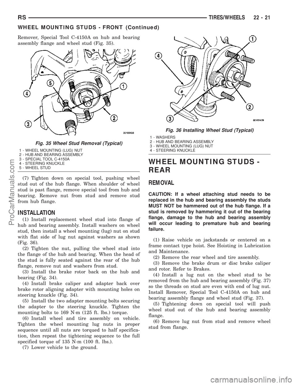
Remover, Special Tool C-4150A on hub and bearing
assembly flange and wheel stud (Fig. 35).
(7) Tighten down on special tool, pushing wheel
stud out of the hub flange. When shoulder of wheel
stud is past flange, remove special tool from hub and
bearing. Remove nut from stud and remove stud
from hub flange.
INSTALLATION
(1) Install replacement wheel stud into flange of
hub and bearing assembly. Install washers on wheel
stud, then install a wheel mounting (lug) nut on stud
with flat side of lug nut against washers as shown
(Fig. 36).
(2) Tighten the nut, pulling the wheel stud into
the flange of the hub and bearing. When the head of
the stud is fully seated against the rear of the hub
flange, remove nut and washers from stud.
(3) Install the brake rotor back on the hub and
bearing (Fig. 34).
(4) Install brake caliper and adapter back over
brake rotor aligning adapter with mounting holes on
steering knuckle (Fig. 34).
(5) Install the two adapter mounting bolts securing
the adapter to the steering knuckle. Tighten the
mounting bolts to 169 N´m (125 ft. lbs.) torque.
(6) Install wheel and tire assembly on vehicle.
Tighten the wheel mounting lug nuts in proper
sequence until all nuts are torqued to half specifica-
tion, then repeat the tightening sequence to the full
specified torque of 135 N´m (100 ft. lbs.).
(7) Lower vehicle to the ground.
WHEEL MOUNTING STUDS -
REAR
REMOVAL
CAUTION: If a wheel attaching stud needs to be
replaced in the hub and bearing assembly the studs
MUST NOT be hammered out of the hub flange. If a
stud is removed by hammering it out of the bearing
flange, damage to the hub and bearing assembly
will occur leading to premature hub and bearing
failure.
(1) Raise vehicle on jackstands or centered on a
frame contact type hoist. See Hoisting in Lubrication
and Maintenance.
(2) Remove the rear wheel and tire assembly.
(3) Remove the brake drum or disc brake caliper
and rotor. Refer to Brakes.
(4) Install a lug nut on the wheel stud to be
removed from the hub and bearing assembly (Fig. 37)
so the threads on stud are even with end of lug nut.
Install Remover, Special Tool C-4150A on hub and
bearing assembly flange and wheel stud (Fig. 37).
(5) Tightening down on special tool will push
wheel stud out of the hub and bearing assembly
flange.
(6) Remove lug nut from stud and remove wheel
stud from flange.
Fig. 35 Wheel Stud Removal (Typical)
1 - WHEEL MOUNTING (LUG) NUT
2 - HUB AND BEARING ASSEMBLY
3 - SPECIAL TOOL C-4150A
4 - STEERING KNUCKLE
5 - WHEEL STUD
Fig. 36 Installing Wheel Stud (Typical)
1 - WASHERS
2 - HUB AND BEARING ASSEMBLY
3 - WHEEL MOUNTING (LUG) NUT
4 - STEERING KNUCKLE
RSTIRES/WHEELS22-21
WHEEL MOUNTING STUDS - FRONT (Continued)
ProCarManuals.com
Page 1737 of 2177
RIGID, SEMI-RIGID, AND FLEXIBLE PLASTIC PARTS TYPES
CODE FAMILY NAME COMMON TRADE NAME TYPICAL APPLICATION
ASA ACRYLONITRILE STYRENE
ACRYLITELURAN S CONSOLES, GRILLES
ABS ACRYLONITRILE
BUTADIENE STYRENETERLURAN9A9PILLARS, CONSOLES,
GRILLES
ABS/PC ABS/PC ALLOY PULSE, PROLOY,
BAYBLENDDOORS, INSTRUMENT
PANELS
ABS/PVC ABS/PV ALLOY PROLOY, PULSE, LUSTRAN,
CYCLOVINDOOR PANELS, GRILLES,
TRIM
BMC BULK MOLDING
COMPOUNDBMC FENDER EXTENSIONS
EMA EHTYLENE METHYL
ACRYLATE/IONOMERSURLYN, EMA, IONOMER BUMPER GUARDS, PADS
METTON METTON METTON GRILLES, KICK PANELS,
RUNNING BOARDS
MPPO MODIFIED
POLYPHENYLENE OXIDEMPPO SPOILER ASSEMBLY
PA POLYAMID ZYTEL, VYDYNE, PA,
MINLONFENDERS, QUARTER PANELS
PET THERMOPLASTIC
POLYESTERRYNITE TRIM
PBT/PPO PBT/PPO ALLOY GERMAX CLADDINGS
PBTP POLYBUTYLENE
THEREPTHALATEPBT, PBTP, POCAN, VALOX WHEEL COVERS, FENDERS,
GRILLES
PBTP/EEBC POLYBUTYLENE
THEREPTHALATE/EEBC
ALLOYBEXLOY,9M9, PBTP/EEBC FASCIAS, ROCKER PANEL,
MOLDINGS
PC POLYCARBONATE LEXAN, MERLON, CALIBRE,
MAKROLON PCTAIL LIGHT LENSES, IP TRIM,
VALANCE PANELS
PC/ABS PC/ABS ALLOY GERMAX, BAY BLENDS,
PULSEDOORS, INSTRUMENT
PANELS
PPO POLYPHENYLENE OXIDE AZDEL, HOSTALEN,
MARLEX, PRFAX, NORYL,
GTX, PPOINTERIOR TRIM, DOOR
PANELS, SPLASH SHIELDS,
STEERING COLUMN SHROUD
PPO/PA POLYPHENYLENE/
POLYAMIDPPO/PA, GTX 910 FENDERS, QUARTER PANELS
PR/FV FIBERGLASS REINFORCED
PLASTICFIBERGLASS, FV, PR/FV BODY PANELS
PS POLYSTYRENE LUSTREX, STYRON, PS DOOR PANELS, DASH
PANELS
RTM RESIN TRANSFER
MOLDING COMPOUNDRTM BODY PANELS
SMC SHEET MOLDED
COMPOUNDSMC BODY PANELS
TMC TRANSFER MOLDING
COMPOUNDTMC GRILLES
23 - 4 BODYRS
BODY (Continued)
ProCarManuals.com
Page 1738 of 2177
CODE FAMILY NAME COMMON TRADE NAME TYPICAL APPLICATION
UP UNSATURATED
POLYESTER
(THERMOSETTING)SMC, BMC, TMC, ZMC, IMC,
XSMC, UPGRILLE OPENING PANEL,
LIFTGATES, FLARESIDE
FENDERS, FENDER
EXTENSIONS
EEBC ETHER/ESTER BLOCKED
CO-POLYMEREEBC BUMPERS
EEBC/PBTP EEBC/POLYBUTYLENE
TEREPTHALATEEEBC, PBTP, BEXLOY BUMPER, ROCKER PANELS
EMPP ETHYLENE MODIFIED
POLYPROPYLENEEMPP BUMPER COVERS
EPDM ETHYLENE/
PROPROPYLENE DIENE
MONOMEREPDM, NORDEL, VISTALON BUMPERS
EPM ETHYLENE/
PROPROPYLENE CO-
POLYMEREPM FENDERS
MPU FOAM POLYURETHANE MPU SPOILERS
PE POLYETHYLENE ALATHON, DYLAN,
LUPOLEN, MARLEX-
PP POLYPROPYLENE
(BLENDS)NORYL, AZDEL, MARLOX,
DYLON, PRAVEXINNER FENDER, SPOILERS,
KICK PANELS
PP/EPDM PP/EPDM ALLOY PP/EPDM SPOILERS, GRILLES
PUR POLYURETHANE COLONELS, PUR, PU FASCIAS, BUMPERS
PUR/PC PUR/PC ALLOY TEXIN BUMPERS
PVC POLYVINYL CHLORIDE APEX, GEON, VINYLITE BODY MOLDINGS, WIRE
INSULATION, STEERING
WHEELS
RIM REACTION INJECTED
MOLDED POLYURETHANERIM, BAYFLEX FRONT FASCIAS, MODULAR
WINDOWS
RRIM REINFORCED REACTION
INJECTED MOLDEDPUR, RRIM FASCIAS, BODY PANELS,
BODY TRIMS
TPE THERMO POLYETHYLENE TPE, HYTREL, BEXLOY-V FASCIAS, BUMPERS,
CLADDINGS
TPO THERMOPOLYOLEFIN POLYTROPE, RENFLEX,
SANTOPRENE, VISAFLEX,
ETA, APEX, TPO, SHIELDS,
CLADDINGSBUMPERS, END CAPS,
TELCAR, RUBBER, STRIPS,
SIGHT, INTERIOR B POST
TPP THERMO-
POLYPROPYLENETPP BUMPERS
TPU THERMOPOLYURETHANE,
POLYESTERTPU, HYTREL, TEXIN,
ESTANEBUMPERS, BODY SIDE,
MOLDINGS, FENDERS,
FASCIAS
RSBODY23-5
BODY (Continued)
ProCarManuals.com
Page 1795 of 2177
INSTRUMENT PANEL
TABLE OF CONTENTS
page page
CLUSTER BEZEL
REMOVAL.............................62
INSTALLATION.........................62
CUP HOLDER
REMOVAL.............................63
INSTALLATION.........................63
GLOVE BOX
REMOVAL.............................63
INSTALLATION.........................63
GLOVE BOX LATCH
REMOVAL.............................63
INSTALLATION.........................63
GLOVE BOX LATCH STRIKER
REMOVAL.............................64
INSTALLATION.........................64
INSTRUMENT PANEL ASSEMBLY
REMOVAL.............................64
INSTALLATION.........................65
INSTRUMENT PANEL CENTER BEZEL
REMOVAL.............................67
INSTALLATION.........................67
INSTRUMENT PANEL END CAP
REMOVAL.............................67INSTALLATION.........................67
INSTRUMENT PANEL TOP COVER
REMOVAL.............................67
INSTALLATION.........................67
LOWER CONSOLE
REMOVAL.............................68
INSTALLATION.........................68
LOWER INSTRUMENT PANEL
REMOVAL.............................68
INSTALLATION.........................68
LOWER STEERING COLUMN COVER
REMOVAL.............................69
INSTALLATION.........................69
STEERING COLUMN COVER BACKING PLATE
REMOVAL.............................69
INSTALLATION.........................69
OVER STEERING COLUMN COVER
REMOVAL.............................69
INSTALLATION.........................69
INSTRUMENT PANEL TOP PAD ASSEMBLY
REMOVAL.............................70
INSTALLATION.........................70
CLUSTER BEZEL
REMOVAL
(1) Disconnect and isolate the battery negative
cable.
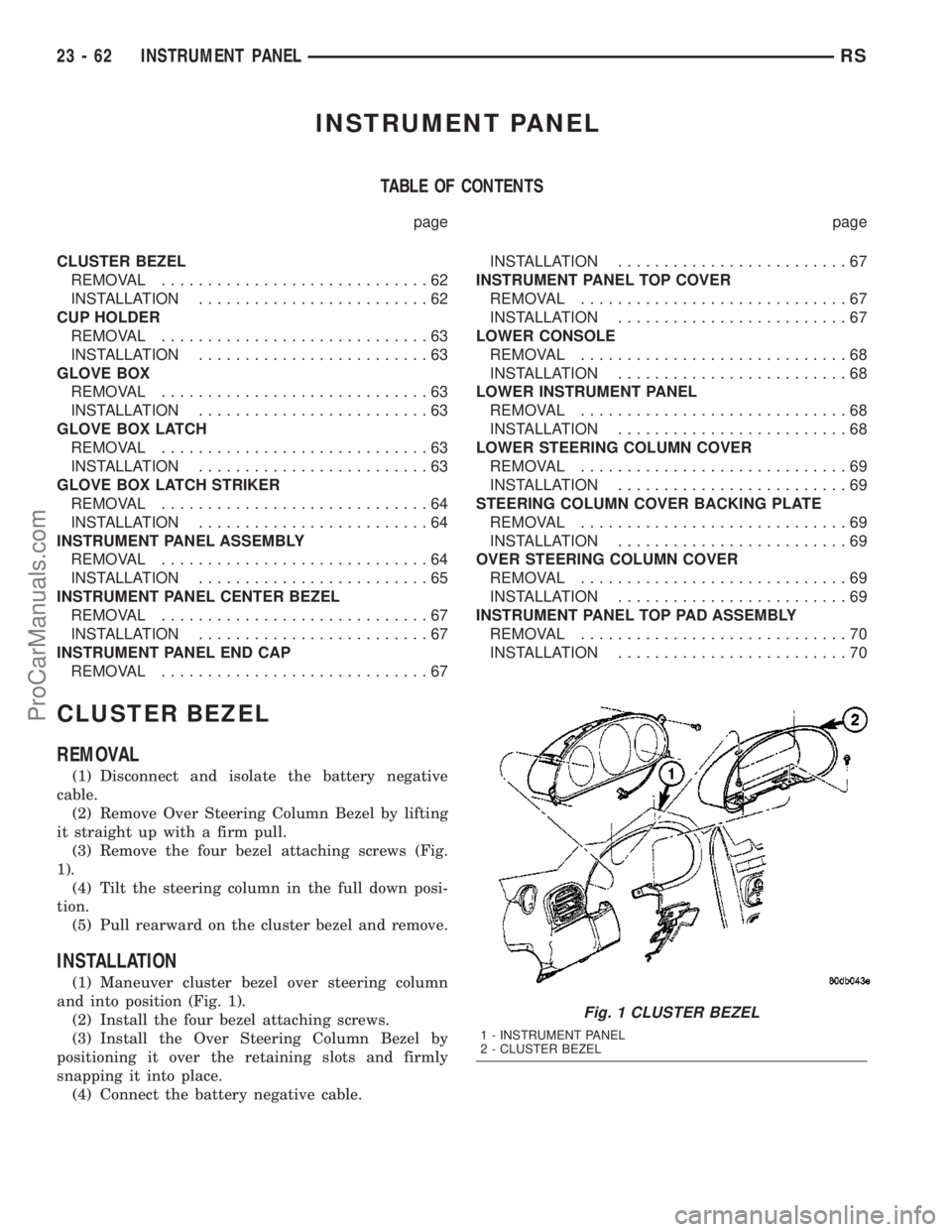
(2) Remove Over Steering Column Bezel by lifting
it straight up with a firm pull.
(3) Remove the four bezel attaching screws (Fig.
1).
(4) Tilt the steering column in the full down posi-
tion.
(5) Pull rearward on the cluster bezel and remove.
INSTALLATION
(1) Maneuver cluster bezel over steering column
and into position (Fig. 1).
(2) Install the four bezel attaching screws.
(3) Install the Over Steering Column Bezel by
positioning it over the retaining slots and firmly
snapping it into place.
(4) Connect the battery negative cable.
Fig. 1 CLUSTER BEZEL
1 - INSTRUMENT PANEL
2 - CLUSTER BEZEL
23 - 62 INSTRUMENT PANELRS
ProCarManuals.com
Page 1797 of 2177
GLOVE BOX LATCH STRIKER
REMOVAL
(1) Open glove box door.
(2) Remove screws holding lock striker to instru-
ment panel.
(3) Remove glove box latch striker.
INSTALLATION
(1) Install the glove box latch striker.
(2) Install the screws holding latch striker to
instrument panel.
(3) Close glove box door.
INSTRUMENT PANEL
ASSEMBLY
REMOVAL
(1) Disconnect and isolate the battery negative
cable.
(2) Remove the lower console:
(a) Remove six retaining screws.
(b) Pull rearward and disconnect the auxiliary
power outlet.
(c) Remove lower console from vehicle.
(3) Remove the bolts attaching the lower supports
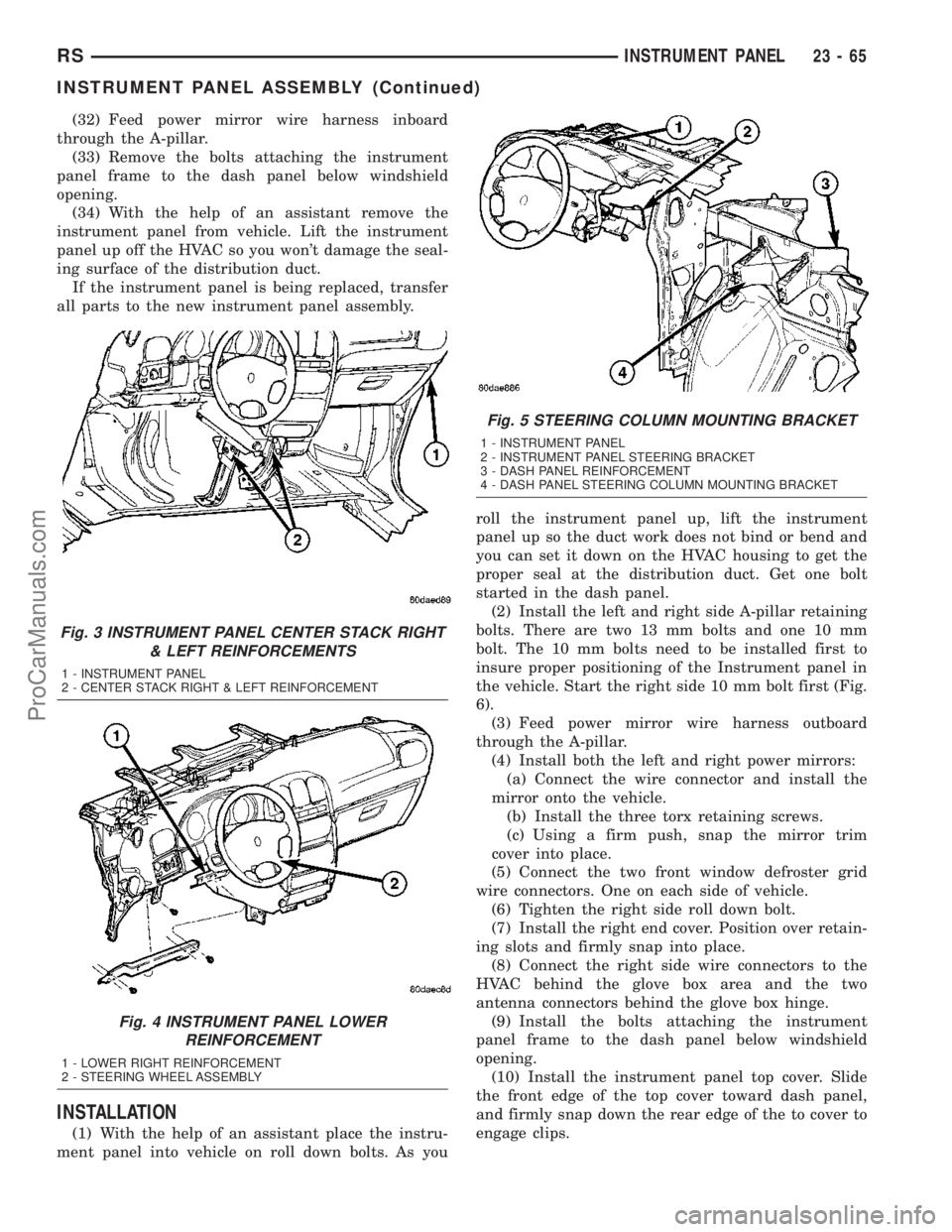
to the instrument panel frame (Fig. 3).
(4) Remove the bolts attaching the lower supports
to the floor pan.
(5) Disconnect the wire connectors from the Pas-
senger Airbag.
(6) Remove the two screws to each right and left
cowl trim covers.
(7) Remove the both left and right side A-pillar
trim covers using a trim stick (special tool #C-4755)
or equivalent gently pry out on the trim covers and
remove.
(8) Remove the glove box:
(a) Push in on sides of glove box bin and lower
door.
(b) Pivot glove box downward and disengage
hinge hooks from instrument panel.
(c) Remove glove box from vehicle.
(9) Disconnect the antenna lead connector from
behind the glove box.
(10) Remove the four screws to the lower steering
column cover.
(11) Remove the eight screws to the steering col-
umn backing plate.
(12) Unclip the Data Link Connector (DLC) from
the steering column backing plate.
(13) Disconnect the left side wiring:
(a) Brake switch.
(b) Main bulkhead connector.(c) Five harness connectors.
(d) Driver airbag connector.
(14) Remove the two screws to the hood release
handle.
(15) Remove five screws to steering column back-
ing plate and remove (Refer to 23 - BODY/INSTRU-
MENT PANEL/KNEE BLOCKER - REMOVAL).
(16) Remove the two steering column shroud
retaining screws. Separate the shrouds and remove
from vehicle.
(17) Remove the screws attaching the instrument
panel reinforcement and remove (Fig. 4).
(18) Disconnect the steering column wiring. There
are seven connectors and then unclip the harness
from the column.
(19) Disconnect the Occupant Restraint Controller
(ORC) harness connector.
(20) Remove the four nuts retaining the steering
column to the dash panel steering column mounting
bracket and lower column to the floor (Fig. 5).
(21) Remove the four nuts attaching the instru-
ment panel to the brake pedal support bracket.
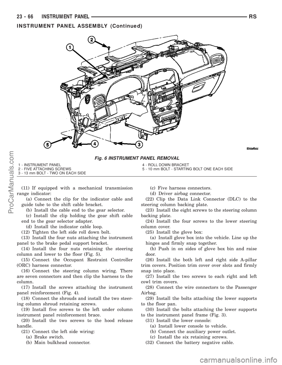
(22) Loosen the left side roll down bolt (Fig. 6).
(23) Remove the left side A-pillar retaining bolts.
There are two 13 mm bolts and one 10 mm bolt.
(24) If equipped with a mechanical transmission
range indicator:
(a) Remove the indicator cable loop.
(b) Remove the clip holding gear shift cable end
to the gear selector adapter.
(c) Pull the cable end from gear selector.
(d) Disconnect the clip for the indicator cable
and guide tube from the shift cable bracket and
move out of the way.
(25) Remove the instrument panel top cover. Using
a trim stick or equivalent, gently pry up on the front
edge of the top cover, pull rearward and remove from
vehicle.
(26) Disconnect the right side wire connectors from
the HVAC behind the glove box area and the two
antenna connectors behind the glove box hinge.
(27) Remove the right end cover by pulling out-
board.
(28) Remove the right side A-pillar retaining bolts.
There are two 13 mm bolts and one 10 mm bolt.
(29) Loosen the right side roll down bolt.
(30) Disconnect the two front window defroster
grid wire connectors. One on each side of vehicle.
(31) Remove both the left and right power mirrors:
(a) Using a trim stick or equivalent, gently pry
out on mirror trim cover.
(b) Open door and remove the three torx retain-
ing screws.
(c) Disconnect the wire connector and remove
mirror from the vehicle.
23 - 64 INSTRUMENT PANELRS
ProCarManuals.com
Page 1798 of 2177
(32) Feed power mirror wire harness inboard
through the A-pillar.
(33) Remove the bolts attaching the instrument
panel frame to the dash panel below windshield
opening.
(34) With the help of an assistant remove the
instrument panel from vehicle. Lift the instrument
panel up off the HVAC so you won't damage the seal-
ing surface of the distribution duct.
If the instrument panel is being replaced, transfer
all parts to the new instrument panel assembly.
INSTALLATION
(1) With the help of an assistant place the instru-
ment panel into vehicle on roll down bolts. As youroll the instrument panel up, lift the instrument
panel up so the duct work does not bind or bend and
you can set it down on the HVAC housing to get the
proper seal at the distribution duct. Get one bolt
started in the dash panel.
(2) Install the left and right side A-pillar retaining
bolts. There are two 13 mm bolts and one 10 mm
bolt. The 10 mm bolts need to be installed first to
insure proper positioning of the Instrument panel in
the vehicle. Start the right side 10 mm bolt first (Fig.
6).
(3) Feed power mirror wire harness outboard
through the A-pillar.
(4) Install both the left and right power mirrors:
(a) Connect the wire connector and install the
mirror onto the vehicle.
(b) Install the three torx retaining screws.
(c) Using a firm push, snap the mirror trim
cover into place.
(5) Connect the two front window defroster grid
wire connectors. One on each side of vehicle.
(6) Tighten the right side roll down bolt.
(7) Install the right end cover. Position over retain-
ing slots and firmly snap into place.
(8) Connect the right side wire connectors to the
HVAC behind the glove box area and the two
antenna connectors behind the glove box hinge.
(9) Install the bolts attaching the instrument
panel frame to the dash panel below windshield
opening.
(10) Install the instrument panel top cover. Slide
the front edge of the top cover toward dash panel,
and firmly snap down the rear edge of the to cover to
engage clips.
Fig. 3 INSTRUMENT PANEL CENTER STACK RIGHT
& LEFT REINFORCEMENTS
1 - INSTRUMENT PANEL
2 - CENTER STACK RIGHT & LEFT REINFORCEMENT
Fig. 4 INSTRUMENT PANEL LOWER
REINFORCEMENT
1 - LOWER RIGHT REINFORCEMENT
2 - STEERING WHEEL ASSEMBLY
Fig. 5 STEERING COLUMN MOUNTING BRACKET
1 - INSTRUMENT PANEL
2 - INSTRUMENT PANEL STEERING BRACKET
3 - DASH PANEL REINFORCEMENT
4 - DASH PANEL STEERING COLUMN MOUNTING BRACKET
RSINSTRUMENT PANEL23-65
INSTRUMENT PANEL ASSEMBLY (Continued)
ProCarManuals.com
Page 1799 of 2177
(11) If equipped with a mechanical transmission
range indicator:
(a) Connect the clip for the indicator cable and
guide tube to the shift cable bracket.
(b) Install the cable end to the gear selector.
(c) Install the clip holding the gear shift cable
end to the gear selector adapter.
(d) Install the indicator cable loop.
(12) Tighten the left side roll down bolt.
(13) Install the four nuts attaching the instrument
panel to the brake pedal support bracket.
(14) Install the four nuts retaining the steering
column and lower to the floor (Fig. 5).
(15) Connect the Occupant Restraint Controller
(ORC) harness connector.
(16) Connect the steering column wiring. There
are seven connectors and then clip the harness to the
column.
(17) Install the screws attaching the instrument
panel reinforcement (Fig. 4).
(18) Connect the shrouds and install the two steer-
ing column shroud retaining screws.
(19) Install five screws to the left under column
instrument panel reinforcement brace.
(20) Install the two screws to the hood release
handle.
(21) Connect the left side wiring:
(a) Brake switch.
(b) Main bulkhead connector.(c) Five harness connectors.
(d) Driver airbag connector.
(22) Clip the Data Link Connector (DLC) to the
steering column backing plate.
(23) Install the eight screws to the steering column
backing plate.
(24) Install the four screws to the lower steering
column cover.
(25) Install the glove box:
(a) Install glove box into the vehicle. Line up the
hinges and firmly snap together.
(b) Push in on sides of glove box bin and raise
door.
(26) Install the both left and right side A-pillar
trim covers. Position trim cover over slots and firmly
snap into place.
(27) Install the two screws to each right and left
cowl trim covers.
(28) Connect the wire connectors to the Passenger
Airbag.
(29) Install the bolts attaching the lower supports
to the floor pan.
(30) Install the bolts attaching the lower supports
to the instrument panel frame (Fig. 3).
(31) Install the lower console:
(a) Install lower console to vehicle.
(b) Connect the auxiliary power outlet.
(c) Install the six retaining screws.
(32) Connect the battery negative cable.
Fig. 6 INSTRUMENT PANEL REMOVAL
1 - INSTRUMENT PANEL
2 - FIVE ATTACHING SCREWS
3 - 13 mm BOLT - TWO ON EACH SIDE4 - ROLL DOWN BRACKET
5 - 10 mm BOLT - STARTING BOLT ONE EACH SIDE
23 - 66 INSTRUMENT PANELRS
INSTRUMENT PANEL ASSEMBLY (Continued)
ProCarManuals.com