2003 CHRYSLER CARAVAN ABS
[x] Cancel search: ABSPage 2096 of 2177
(4) Carefully pour the proper pre-mixed engine
coolant solution into the rear heater core through a
funnel until coolant begins to appear at the lower
hose fitting of the heater core.
(5) Use absorbent toweling to clean up any engine
coolant spills from the preceding operation.
(6) Reconnect the heater hoses to the rear heater
core. (Refer to 24 - HEATING & AIR CONDITION-
ING/PLUMBING - REAR/HEATER HOSE - INSTAL-
LATION).
(7) Refill the engine cooling system. (Refer to 7 -
COOLING - STANDARD PROCEDURE - COOLING
SYSTEM REFILL).
THERMAL CYCLING
If the rear heater core was emptied and was not
pre-filled, it will be necessary to thermal cycle the
vehicle at least two times to ensure that the rear
heater core is properly filled.
(1) Refill the engine cooling system. (Refer to 7 -
COOLING - STANDARD PROCEDURE - COOLING
SYSTEM REFILL).
(2) Start the engine and allow it to operate until
the thermostat opens.
(3) Turn the engine off and allow it to cool.
(4) With the engine cold and not running, check
and top off the engine coolant level as necessary.
(Refer to 7 - COOLING - STANDARD PROCEDURE
- COOLANT LEVEL CHECK) and (Refer to 7 -
COOLING - STANDARD PROCEDURE - COOLANT
- ADDING).
(5) Start the engine and allow it to operate until
the thermostat opens again.
(6) Turn the engine off and allow it to cool down
again.
(7) With the engine cold and not running, check
and top off the engine coolant level as necessary.
(Refer to 7 - COOLING - STANDARD PROCEDURE
- COOLANT LEVEL CHECK) and (Refer to 7 -
COOLING - STANDARD PROCEDURE - COOLANT
- ADDING).
(8) Check the performance of the rear heater.
Refer to REAR HEATER PERFORMANCE CHECK .
REAR HEATER PERFORMANCE CHECK
Successful completion of the rear heater perfor-
mance check will confirm that the rear heater core is
properly filled with engine coolant. If the check is not
successful, either there is still air trapped in the rear
heater core or the rear heater plumbing is restricted.
This check should be performed with the vehicle in a
shop where the ambient temperature is about 21É C
(70É F).
(1) Start the engine and allow it to idle until it
warms up to normal operating temperature.(2) Adjust the heater-A/C controls so that the front
heater is turned Off, the rear heater is set for full
Heat, and the rear blower motor is at its highest
speed setting.
(3) Use an accurate test thermometer to measure
the temperature of the air being discharged from the
rear heater outlet located at the base of the right
C-pillar.
(4) Proper discharge air temperature readings
should be from 57É to 63É C (135É to 145É F).
REMOVAL
WARNING: REFER TO THE APPLICABLE WARN-
INGS AND CAUTIONS FOR THIS SYSTEM BEFORE
PERFORMING THE FOLLOWING OPERATION.
(Refer to 24 - HEATING & AIR CONDITIONING/
PLUMBING FRONT - WARNING - HEATER PLUMB-
ING).
(1) Drain the engine cooling system. (Refer to 7 -
COOLING - STANDARD PROCEDURE - COOLING
SYSTEM DRAIN).
(2) Remove the right quarter trim panel and right
D-pillar trim panel from the quarter inner panel.
(Refer to 23 - BODY/INTERIOR/QUARTER TRIM
PANEL - REMOVAL).
(3) Remove the rear heater distribution duct from
the right quarter inner panel. (Refer to 24 - HEAT-
ING & AIR CONDITIONING/DISTRIBUTION -
REAR/REAR HEATER DISTRIBUTION DUCT -
REMOVAL).
(4) Remove the screw that secures the back of the
rear heater-A/C unit housing to the right D-pillar.
(5) Remove the screw that secures the front of the
rear heater-A/C unit housing to the right quarter
inner panel.
(6) Take the proper precautions to protect the car-
peting below the rear heater core from spilled engine
coolant and have absorbent toweling readily avail-
able to mop up any spills.
(7) Disconnect the heater hoses at the rear heater
core. (Refer to 24 - HEATING & AIR CONDITION-
ING/PLUMBING - REAR/HEATER HOSE - REMOV-
AL).
(8) Install plugs in, or tape over the opened heater
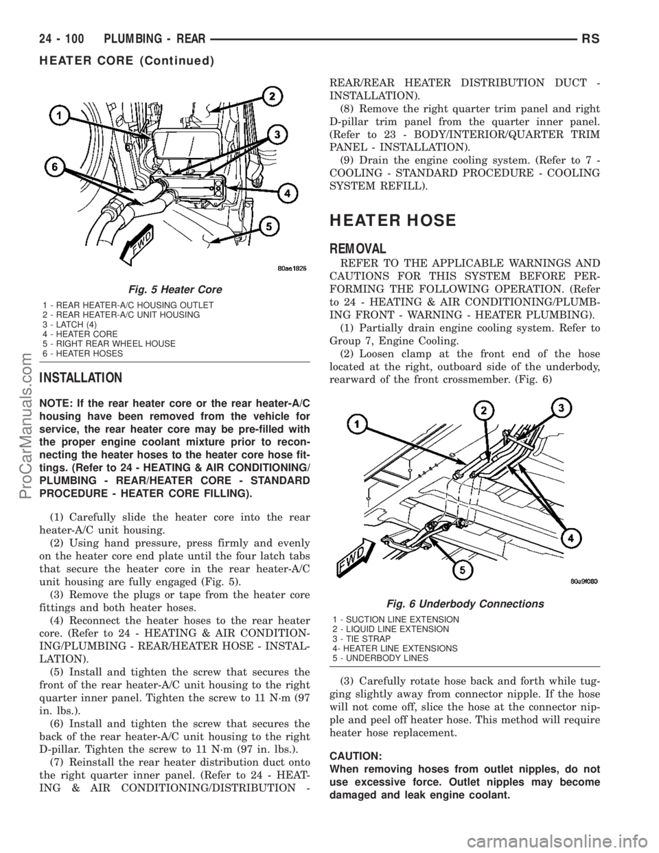
core fittings and both heater hoses (Fig. 5).
(9) Use absorbent toweling to clean up any engine
coolant spills from the preceding operation.
(10) Release the four latch tabs that secure the
heater core in the rear heater-A/C unit housing.
(11) Carefully pull the heater core straight out of
the rear heater-A/C unit housing.
(12) Use absorbent toweling to clean up any
engine coolant spills from the preceding operation.
RSPLUMBING - REAR24-99
HEATER CORE (Continued)
ProCarManuals.com
Page 2097 of 2177
INSTALLATION
NOTE: If the rear heater core or the rear heater-A/C
housing have been removed from the vehicle for
service, the rear heater core may be pre-filled with
the proper engine coolant mixture prior to recon-
necting the heater hoses to the heater core hose fit-
tings. (Refer to 24 - HEATING & AIR CONDITIONING/
PLUMBING - REAR/HEATER CORE - STANDARD
PROCEDURE - HEATER CORE FILLING).
(1) Carefully slide the heater core into the rear
heater-A/C unit housing.
(2) Using hand pressure, press firmly and evenly
on the heater core end plate until the four latch tabs
that secure the heater core in the rear heater-A/C
unit housing are fully engaged (Fig. 5).
(3) Remove the plugs or tape from the heater core
fittings and both heater hoses.
(4) Reconnect the heater hoses to the rear heater
core. (Refer to 24 - HEATING & AIR CONDITION-
ING/PLUMBING - REAR/HEATER HOSE - INSTAL-
LATION).
(5) Install and tighten the screw that secures the
front of the rear heater-A/C unit housing to the right
quarter inner panel. Tighten the screw to 11 N´m (97
in. lbs.).
(6) Install and tighten the screw that secures the
back of the rear heater-A/C unit housing to the right
D-pillar. Tighten the screw to 11 N´m (97 in. lbs.).
(7) Reinstall the rear heater distribution duct onto
the right quarter inner panel. (Refer to 24 - HEAT-
ING & AIR CONDITIONING/DISTRIBUTION -REAR/REAR HEATER DISTRIBUTION DUCT -
INSTALLATION).
(8) Remove the right quarter trim panel and right
D-pillar trim panel from the quarter inner panel.
(Refer to 23 - BODY/INTERIOR/QUARTER TRIM
PANEL - INSTALLATION).
(9) Drain the engine cooling system. (Refer to 7 -
COOLING - STANDARD PROCEDURE - COOLING
SYSTEM REFILL).
HEATER HOSE
REMOVAL
REFER TO THE APPLICABLE WARNINGS AND
CAUTIONS FOR THIS SYSTEM BEFORE PER-
FORMING THE FOLLOWING OPERATION. (Refer
to 24 - HEATING & AIR CONDITIONING/PLUMB-
ING FRONT - WARNING - HEATER PLUMBING).
(1) Partially drain engine cooling system. Refer to
Group 7, Engine Cooling.
(2) Loosen clamp at the front end of the hose
located at the right, outboard side of the underbody,
rearward of the front crossmember. (Fig. 6)
(3) Carefully rotate hose back and forth while tug-
ging slightly away from connector nipple. If the hose
will not come off, slice the hose at the connector nip-
ple and peel off heater hose. This method will require
heater hose replacement.
CAUTION:
When removing hoses from outlet nipples, do not
use excessive force. Outlet nipples may become
damaged and leak engine coolant.
Fig. 5 Heater Core
1 - REAR HEATER-A/C HOUSING OUTLET
2 - REAR HEATER-A/C UNIT HOUSING
3 - LATCH (4)
4 - HEATER CORE
5 - RIGHT REAR WHEEL HOUSE
6 - HEATER HOSES
Fig. 6 Underbody Connections
1 - SUCTION LINE EXTENSION
2 - LIQUID LINE EXTENSION
3 - TIE STRAP
4- HEATER LINE EXTENSIONS
5 - UNDERBODY LINES
24 - 100 PLUMBING - REARRS
HEATER CORE (Continued)
ProCarManuals.com
Page 2101 of 2177
REMOVAL
REMOVAL - REAR HEATER LINES
(1) Raise and support vehicle.
(2) Pinch off rubber heater line hose.
(3) Disconnect quick connect fitting at C-pillar.
(4) Loosen one screw and remove the other screw
at each of the three brackets holding the front of the
line to the underbody.
(5) Lower rear of line and drain coolant into a
suitable container.
(6) Loosen hose clamps at front of line and remove
line from vehicle.
REMOVAL - REAR AIR CONDITIONING LINES
(1) Recover A/C system.
(2) Hoist and support vehicle.
(3) Loosen one screw and remove the other screw
at each of the three brackets holding the A/C lines to
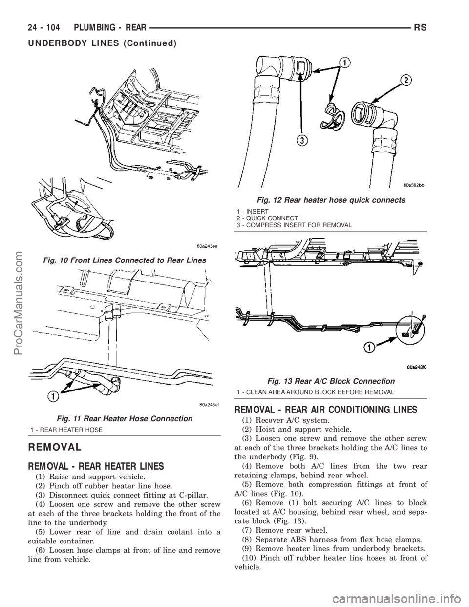
the underbody (Fig. 9).
(4) Remove both A/C lines from the two rear
retaining clamps, behind rear wheel.
(5) Remove both compression fittings at front of
A/C lines (Fig. 10).
(6) Remove (1) bolt securing A/C lines to block
located at A/C housing, behind rear wheel, and sepa-
rate block (Fig. 13).
(7) Remove rear wheel.
(8) Separate ABS harness from flex hose clamps.
(9) Remove heater lines from underbody brackets.
(10) Pinch off rubber heater line hoses at front of
vehicle.
Fig. 10 Front Lines Connected to Rear Lines
Fig. 11 Rear Heater Hose Connection
1 - REAR HEATER HOSE
Fig. 12 Rear heater hose quick connects
1 - INSERT
2 - QUICK CONNECT
3 - COMPRESS INSERT FOR REMOVAL
Fig. 13 Rear A/C Block Connection
1 - CLEAN AREA AROUND BLOCK BEFORE REMOVAL
24 - 104 PLUMBING - REARRS
UNDERBODY LINES (Continued)
ProCarManuals.com
Page 2102 of 2177
(11) Loosen hose clamps at front of heater lines
and allow them to hang from vehicle.
(12) Remove rear A/C lines from vehicle.
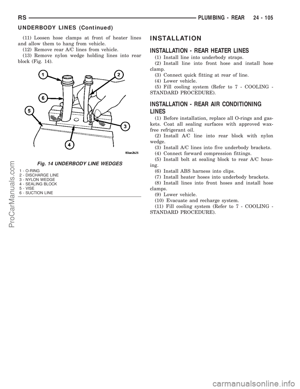
(13) Remove nylon wedge holding lines into rear
block (Fig. 14).INSTALLATION
INSTALLATION - REAR HEATER LINES
(1) Install line into underbody straps.
(2) Install line into front hose and install hose
clamp.
(3) Connect quick fitting at rear of line.
(4) Lower vehicle.
(5) Fill cooling system (Refer to 7 - COOLING -
STANDARD PROCEDURE).
INSTALLATION - REAR AIR CONDITIONING
LINES
(1) Before installation, replace all O-rings and gas-
kets. Coat all sealing surfaces with approved wax-
free refrigerant oil.
(2) Install A/C line into rear block with nylon
wedge.
(3) Install A/C lines into five underbody brackets.
(4) Connect forward compression fittings.
(5) Install bolt at sealing block to rear A/C hous-
ing.
(6) Install ABS harness into clips.
(7) Install heater hoses into underbody brackets.
(8) Install lines into front hoses and install hose
clamps.
(9) Lower vehicle.
(10) Evacuate and recharge system.
(11) Fill cooling system (Refer to 7 - COOLING -
STANDARD PROCEDURE).
Fig. 14 UNDERBODY LINE WEDGES
1 - O-RING
2 - DISCHARGE LINE
3 - NYLON WEDGE
4 - SEALING BLOCK
5 - VISE
6 - SUCTION LINE
RSPLUMBING - REAR24 - 105
UNDERBODY LINES (Continued)
ProCarManuals.com
Page 2113 of 2177
The following is a list of the monitored compo-
nents:
²Comprehensive Components
²Oxygen Sensor Monitor
²Oxygen Sensor Heater Monitor
²Catalyst Monitor
COMPREHENSIVE COMPONENTS
Along with the major monitors, OBD II requires
that the diagnostic system monitor any component
that could affect emissions levels. In many cases,
these components were being tested under OBD I.
The OBD I requirements focused mainly on testing
emissions-related components for electrical opens and
shorts.
However, OBD II also requires that inputs from
powertrain components to the PCM be tested for
rationality, and that outputs to powertrain compo-
nents from the PCM be tested forfunctionality.
Methods for monitoring the various Comprehensive
Component monitoring include:
(1) Circuit Continuity
²Open
²Shorted high
²Shorted to ground
(2) Rationality or Proper Functioning
²Inputs tested for rationality
²Outputs tested for functionality
NOTE: Comprehensive component monitors are
continuous. Therefore, enabling conditions do not
apply.
Input RationalityÐWhile input signals to the
PCM are constantly being monitored for electrical
opens and shorts, they are also tested for rationality.
This means that the input signal is compared against
other inputs and information to see if it makes sense
under the current conditions.
PCM sensor inputs that are checked for rationality
include:
²Manifold Absolute Pressure (MAP) Sensor
²Oxygen Sensor (O2S)
²Engine Coolant Temperature (ECT) Sensor
²Camshaft Position (CMP) Sensor
²Vehicle Speed Sensor
²Crankshaft Position (CKP) Sensor
²Intake/inlet Air Temperature (IAT) Sensor
²Throttle Position (TPS) Sensor
²Ambient Temperature Sensors
²Power Steering Switch
²Oxygen Sensor Heater
²Brake Switch
²Leak Detection Pump Switch or NVLD switch (if
equipped)
²P/N SwitchOutput FunctionalityÐPCM outputs are tested
for functionality in addition to testing for opens and
shorts. When the PCM provides a voltage to an out-
put component, it can verify that the command was
carried out by monitoring specific input signals for
expected changes. For example, when the PCM com-
mands the Idle Air Control (IAC) Motor to a specific
position under certain operating conditions, it expects
to see a specific (target) idle speed (RPM). If it does
not, it stores a DTC.
PCM outputs monitored for functionality include:
²Fuel Injectors
²Ignition Coils
²Idle Air Control
²Purge Solenoid
²EGR Solenoid (if equipped)
²LDP Solenoid or NVLD solenoid (if equipped)
²Radiator Fan Control
²Trans Controls
OXYGEN SENSOR (O2S) MONITOR
DESCRIPTIONÐEffective control of exhaust
emissions is achieved by an oxygen feedback system.
The most important element of the feedback system
is the O2S. The O2S is located in the exhaust path.
Once it reaches operating temperature 300É to 350ÉC
(572É to 662ÉF), the sensor generates a voltage that
is inversely proportional to the amount of oxygen in
the exhaust. When there is a large amount of oxygen
in the exhaust caused by a lean condition, the sensor
produces a low voltage, below 450 mV. When the oxy-
gen content is lower, caused by a rich condition, the
sensor produces a higher voltage, above 450mV (volt-
ages are offset by 2.5 volts on NGC vehicles).
The information obtained by the sensor is used to
calculate the fuel injector pulse width. The PCM is
programmed to maintain the optimum air/fuel ratio.
At this mixture ratio, the catalyst works best to
remove hydrocarbons (HC), carbon monoxide (CO)
and nitrous oxide (NOx) from the exhaust.
The O2S is also the main sensing element for the
EGR (if equipped), Catalyst and Fuel Monitors.
The O2S may fail in any or all of the following
manners:
²Slow response rate (Big Slope)
²Reduced output voltage (Half Cycle)
²Heater Performance
Slow Response Rate (Big Slope)ÐResponse rate
is the time required for the sensor to switch from
lean to rich signal output once it is exposed to a
richer than optimum A/F mixture or vice versa. As
the PCM adjusts the air/fuel ratio, the sensor must
be able to rapidly detect the change. As the sensor
ages, it could take longer to detect the changes in the
oxygen content of the exhaust gas. The rate of
change that an oxygen sensor experiences is called
25 - 2 EMISSIONS CONTROLRS
EMISSIONS CONTROL (Continued)
ProCarManuals.com
Page 2115 of 2177
OPERATIONÐThe Oxygen Sensor Heater Moni-
tor begins after the ignition has been turned OFF.
The PCM sends a 5 volt bias to the oxygen sensor
every 1.6 seconds. The PCM keeps it biased for 35
ms each time. As the sensor cools down, the resis-
tance increases and the PCM reads the increase in
voltage. Once voltage has increased to a predeter-
mined amount, higher than when the test started,
the oxygen sensor is cool enough to test heater oper-
ation.
When the oxygen sensor is cool enough, the PCM
energizes the ASD relay. Voltage to the O2 sensor
begins to increase the temperature. As the sensor
temperature increases, the internal resistance
decreases. The PCM continues biasing the 5 volt sig-
nal to the sensor. Each time the signal is biased, the
PCM reads a voltage decrease. When the PCM
detects a voltage decrease of a predetermined value
for several biased pulses, the test passes.
The heater elements are tested each time the
engine is turned OFF if all the enabling conditions
are met. If the monitor fails, the PCM stores a
maturing fault and a Freeze Frame is entered. If two
consecutive tests fail, a DTC is stored. Because the
ignition is OFF, the MIL is illuminated at the begin-
ning of the next key cycle.
Enabling ConditionsÐThe following conditions
must be met for the PCM to run the oxygen sensor
heater test:
²Engine run time of at least 3 minutes
²Engine run time at a predetermined speed
and throttle opening.
²Key OFF power down
²Battery voltage of at least 10 volts
²Sufficient Oxygen Sensor cool down
Pending ConditionsÐThere are not conditions or
situations that prompt conflict or suspension of test-
ing. The oxygen sensor heater test is not run pending
resolution of MIL illumination due to oxygen sensor
failure.
SuspendÐThere are no conditions which exist for
suspending the Heater Monitor.
CATALYST MONITOR
To comply with clean air regulations, vehicles are
equipped with catalytic converters. These converters
reduce the emission of hydrocarbons, oxides of nitro-
gen and carbon monoxide.
Normal vehicle miles or engine misfire can cause a
catalyst to decay. A meltdown of the ceramic core can
cause a reduction of the exhaust passage. This can
increase vehicle emissions and deteriorate engine
performance, driveability and fuel economy.
The catalyst monitor uses dual oxygen sensors
(O2S's) to monitor the efficiency of the converter. The
dual O2S strategy is based on the fact that as a cat-alyst deteriorates, its oxygen storage capacity and its
efficiency are both reduced. By monitoring the oxy-
gen storage capacity of a catalyst, its efficiency can
be indirectly calculated. The upstream O2S is used to
detect the amount of oxygen in the exhaust gas
before the gas enters the catalytic converter. The
PCM calculates the A/F mixture from the output of
the O2S. A low voltage indicates high oxygen content
(lean mixture). A high voltage indicates a low content
of oxygen (rich mixture).
When the upstream O2S detects a lean condition,
there is an abundance of oxygen in the exhaust gas.
A functioning converter would store this oxygen so it
can use it for the oxidation of HC and CO. As the
converter absorbs the oxygen, there will be a lack of
oxygen downstream of the converter. The output of
the downstream O2S will indicate limited activity in
this condition.
As the converter loses the ability to store oxygen,
the condition can be detected from the behavior of
the downstream O2S. When the efficiency drops, no
chemical reaction takes place. This means the con-
centration of oxygen will be the same downstream as
upstream. The output voltage of the downstream
O2S copies the voltage of the upstream sensor. The
only difference is a time lag (seen by the PCM)
between the switching of the O2S's.
To monitor the system, the number of lean-to-rich
switches of upstream and downstream O2S's is
counted. The ratio of downstream switches to
upstream switches is used to determine whether the
catalyst is operating properly. An effective catalyst
will have fewer downstream switches than it has
upstream switches i.e., a ratio closer to zero. For a
totally ineffective catalyst, this ratio will be one-to-
one, indicating that no oxidation occurs in the device.
The system must be monitored so that when cata-
lyst efficiency deteriorates and exhaust emissions
increase to over the legal limit, the MIL (check
engine lamp) will be illuminated.
Monitor OperationÐTo monitor catalyst effi-
ciency, the PCM expands the rich and lean switch
points of the heated oxygen sensor. With extended
switch points, the air/fuel mixture runs richer and
leaner to overburden the catalytic converter. Once
the test is started, the air/fuel mixture runs rich and
lean and the O2 switches are counted. A switch is
counted when an oxygen sensor signal goes from
below the lean threshold to above the rich threshold.
The number of Rear O2 sensor switches is divided by
the number of Front O2 sensor switches to determine
the switching ratio.
The test runs for 20 seconds. As catalyst efficiency
deteriorated over the life of the vehicle, the switch
rate at the downstream sensor approaches that of the
upstream sensor. If at any point during the test
25 - 4 EMISSIONS CONTROLRS
EMISSIONS CONTROL (Continued)
ProCarManuals.com
Page 2118 of 2177
Effective control of exhaust emissions is achieved
by an oxygen feedback system. The most important
element of the feedback system is the O2S. The O2S
is located in the exhaust path. Once it reaches oper-
ating temperatures of 300É to 350ÉC (572 É to 662ÉF),
the sensor generates a voltage that is inversely pro-
portional to the amount of oxygen in the exhaust.
The information obtained by the sensor is used to
calculate the fuel injector pulse width. This main-
tains a 14.7 to 1 Air Fuel (A/F) ratio. At this mixture
ratio, the catalyst works best to remove hydrocarbons
(HC), carbon monoxide (CO) and nitrogen oxide
(NOx) from the exhaust.
The voltage readings taken from the O2S are very
temperature sensitive. The readings are not accurate
below 300ÉC. Heating of the O2S is done to allow the
engine controller to shift to closed loop control as
soon as possible. The heating element used to heat
the O2S must be tested to ensure that it is heating
the sensor properly.
The O2S circuit is monitored for a drop in voltage.
The sensor output is used to test the heater by iso-
lating the effect of the heater element on the O2S
output voltage from the other effects.
EGR MONITOR (if equipped)
The Powertrain Control Module (PCM) performs
an on-board diagnostic check of the EGR system.
The EGR monitor is used to test whether the EGR
system is operating within specifications. The diag-
nostic check activates only during selected engine/
driving conditions. When the conditions are met, the
EGR is turned off (solenoid energized) and the O2S
compensation control is monitored. Turning off the
EGR shifts the air fuel (A/F) ratio in the lean direc-
tion. The O2S data should indicate an increase in the
O2 concentration in the combustion chamber when
the exhaust gases are no longer recirculated. While
this test does not directly measure the operation of
the EGR system, it can be inferred from the shift in
the O2S data whether the EGR system is operating
correctly. Because the O2S is being used, the O2S
test must pass its test before the EGR test. Also
looks at EGR linear potentiometer for feedback.
MISFIRE MONITOR
Excessive engine misfire results in increased cata-
lyst temperature and causes an increase in HC emis-
sions. Severe misfires could cause catalyst damage.
To prevent catalytic convertor damage, the PCM
monitors engine misfire.
The Powertrain Control Module (PCM) monitors
for misfire during most engine operating conditions
(positive torque) by looking at changes in the crank-
shaft speed. If a misfire occurs the speed of the
crankshaft will vary more than normal.FUEL SYSTEM MONITOR
To comply with clean air regulations, vehicles are
equipped with catalytic converters. These converters
reduce the emission of hydrocarbons, oxides of nitro-
gen and carbon monoxide. The catalyst works best
when the air fuel (A/F) ratio is at or near the opti-
mum of 14.7 to 1.
The PCM is programmed to maintain the optimum
air/fuel ratio. This is done by making short term cor-
rections in the fuel injector pulse width based on the
O2S output. The programmed memory acts as a self
calibration tool that the engine controller uses to
compensate for variations in engine specifications,
sensor tolerances and engine fatigue over the life
span of the engine. By monitoring the actual air-fuel
ratio with the O2S (short term) and multiplying that
with the program long-term (adaptive) memory and
comparing that to the limit, it can be determined
whether it will pass an emissions test. If a malfunc-
tion occurs such that the PCM cannot maintain the
optimum A/F ratio, then the MIL will be illuminated.
CATALYST MONITOR
To comply with clean air regulations, vehicles are
equipped with catalytic converters. These converters
reduce the emission of hydrocarbons, oxides of nitro-
gen and carbon monoxide.
Normal vehicle miles or engine misfire can cause a
catalyst to decay. A meltdown of the ceramic core can
cause a reduction of the exhaust passage. This can
increase vehicle emissions and deteriorate engine
performance, driveability and fuel economy.
The catalyst monitor uses dual oxygen sensors
(O2S's) to monitor the efficiency of the converter. The
dual O2S's strategy is based on the fact that as a cat-
alyst deteriorates, its oxygen storage capacity and its
efficiency are both reduced. By monitoring the oxy-
gen storage capacity of a catalyst, its efficiency can
be indirectly calculated. The upstream O2S is used to
detect the amount of oxygen in the exhaust gas
before the gas enters the catalytic converter. The
PCM calculates the A/F mixture from the output of
the O2S. A low voltage indicates high oxygen content
(lean mixture). A high voltage indicates a low content
of oxygen (rich mixture).
When the upstream O2S detects a lean condition,
there is an abundance of oxygen in the exhaust gas.
A functioning converter would store this oxygen so it
can use it for the oxidation of HC and CO. As the
converter absorbs the oxygen, there will be a lack of
oxygen downstream of the converter. The output of
the downstream O2S will indicate limited activity in
this condition.
As the converter loses the ability to store oxygen,
the condition can be detected from the behavior of
the downstream O2S. When the efficiency drops, no
RSEMISSIONS CONTROL25-7
EMISSIONS CONTROL (Continued)
ProCarManuals.com
Page 2125 of 2177
ORVR
OPERATION
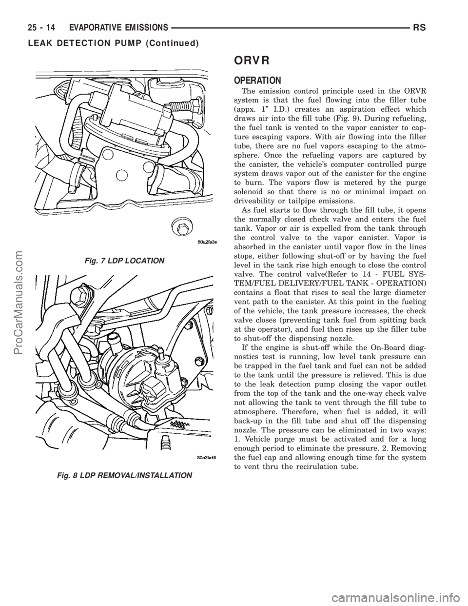
The emission control principle used in the ORVR
system is that the fuel flowing into the filler tube
(appx. 1º I.D.) creates an aspiration effect which
draws air into the fill tube (Fig. 9). During refueling,
the fuel tank is vented to the vapor canister to cap-
ture escaping vapors. With air flowing into the filler
tube, there are no fuel vapors escaping to the atmo-
sphere. Once the refueling vapors are captured by
the canister, the vehicle's computer controlled purge
system draws vapor out of the canister for the engine
to burn. The vapors flow is metered by the purge
solenoid so that there is no or minimal impact on
driveability or tailpipe emissions.
As fuel starts to flow through the fill tube, it opens
the normally closed check valve and enters the fuel
tank. Vapor or air is expelled from the tank through
the control valve to the vapor canister. Vapor is
absorbed in the canister until vapor flow in the lines
stops, either following shut-off or by having the fuel
level in the tank rise high enough to close the control
valve. The control valve(Refer to 14 - FUEL SYS-
TEM/FUEL DELIVERY/FUEL TANK - OPERATION)
contains a float that rises to seal the large diameter
vent path to the canister. At this point in the fueling
of the vehicle, the tank pressure increases, the check
valve closes (preventing tank fuel from spitting back
at the operator), and fuel then rises up the filler tube
to shut-off the dispensing nozzle.
If the engine is shut-off while the On-Board diag-
nostics test is running, low level tank pressure can
be trapped in the fuel tank and fuel can not be added
to the tank until the pressure is relieved. This is due
to the leak detection pump closing the vapor outlet
from the top of the tank and the one-way check valve
not allowing the tank to vent through the fill tube to
atmosphere. Therefore, when fuel is added, it will
back-up in the fill tube and shut off the dispensing
nozzle. The pressure can be eliminated in two ways:
1. Vehicle purge must be activated and for a long
enough period to eliminate the pressure. 2. Removing
the fuel cap and allowing enough time for the system
to vent thru the recirulation tube.
Fig. 7 LDP LOCATION
Fig. 8 LDP REMOVAL/INSTALLATION
25 - 14 EVAPORATIVE EMISSIONSRS
LEAK DETECTION PUMP (Continued)
ProCarManuals.com