2003 CHRYSLER CARAVAN ABS
[x] Cancel search: ABSPage 2024 of 2177
(2) Install and tighten the two screws that secure
the power module to the evaporator housing. Tighten
the screws to 2 N´m (18 in. lbs.).
(3) Reconnect the blower motor pigtail wire con-
nector to the power module connector receptacle.
(4) Reconnect the instrument panel wire harness
connector for the power module to the module con-
nector receptacle.
(5) Flex both sides of the glove box bin inward
near the top far enough for the rubber glove box stop
bumpers to clear the sides of the glove box opening,
then roll the glove box upward.
(6) Close and latch the glove box.
(7) Reconnect the battery negative cable.
RECIRCULATION DOOR
ACTUATOR
DESCRIPTION
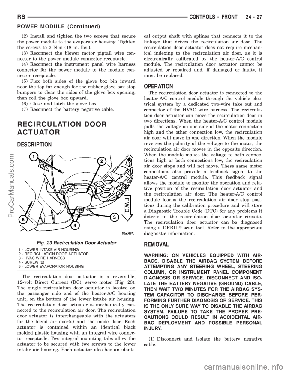
The recirculation door actuator is a reversible,
12-volt Direct Current (DC), servo motor (Fig. 23).
The single recirculation door actuator is located on
the passenger side end of the heater-A/C housing
unit, on the bottom of the lower intake air housing.
The recirculation door actuator is mechanically con-
nected to the recirculation air door. The recirculation
door actuator is interchangeable with the actuators
for the blend air door(s) and the mode door. Each
actuator is contained within an identical black
molded plastic housing with an integral wire connec-
tor receptacle. Two integral mounting tabs allow the
actuator to be secured with two screws to the lower
intake air housing. Each actuator also has an identi-cal output shaft with splines that connects it to the
linkage that drives the recirculation air door. The
recirculation door actuator does not require mechan-
ical indexing to the recirculation air door, as it is
electronically calibrated by the heater-A/C control
module. The recirculation door actuator cannot be
adjusted or repaired and, if damaged or faulty, it
must be replaced.
OPERATION
The recirculation door actuator is connected to the
heater-A/C control module through the vehicle elec-
trical system by a dedicated two-wire take out and
connector of the HVAC wire harness. The recircula-
tion door actuator can move the recirculation door in
two directions. When the heater-A/C control module
pulls the voltage on one side of the motor connection
high and the other connection low, the recirculation
air door will move in one direction. When the module
reverses the polarity of the voltage to the motor, the
recirculation air door moves in the opposite direction.
When the module makes the voltage to both connec-
tions high or both connections low, the recirculation
air door stops and will not move. These same motor
connections also provide a feedback signal to the
heater-A/C control module. This feedback signal
allows the module to monitor the operation and rela-
tive position of the recirculation door actuator and
the recirculation air door. The heater-A/C control
module learns the recirculation air door stop posi-
tions during the calibration procedure and will store
a Diagnostic Trouble Code (DTC) for any problems it
detects in the recirculation door actuator circuits.
The recirculation door actuator can be diagnosed
using a DRBIIItscan tool. Refer to the appropriate
diagnostic information.
REMOVAL
WARNING: ON VEHICLES EQUIPPED WITH AIR-
BAGS, DISABLE THE AIRBAG SYSTEM BEFORE
ATTEMPTING ANY STEERING WHEEL, STEERING
COLUMN, OR INSTRUMENT PANEL COMPONENT
DIAGNOSIS OR SERVICE. DISCONNECT AND ISO-
LATE THE BATTERY NEGATIVE (GROUND) CABLE,
THEN WAIT TWO MINUTES FOR THE AIRBAG SYS-
TEM CAPACITOR TO DISCHARGE BEFORE PER-
FORMING FURTHER DIAGNOSIS OR SERVICE. THIS
IS THE ONLY SURE WAY TO DISABLE THE AIRBAG
SYSTEM. FAILURE TO TAKE THE PROPER PRE-
CAUTIONS COULD RESULT IN ACCIDENTAL AIR-
BAG DEPLOYMENT AND POSSIBLE PERSONAL
INJURY.
(1) Disconnect and isolate the battery negative
cable.
Fig. 23 Recirculation Door Actuator
1 - LOWER INTAKE AIR HOUSING
2 - RECIRCULATION DOOR ACTUATOR
3 - HVAC WIRE HARNESS
4 - SCREW (2)
5 - LOWER EVAPORATOR HOUSING
RSCONTROLS - FRONT24-27
POWER MODULE (Continued)
ProCarManuals.com
Page 2026 of 2177
CONTROLS - REAR
TABLE OF CONTENTS
page page
A/C-HEATER CONTROL
REMOVAL.............................29
INSTALLATION.........................29
BLEND DOOR ACTUATOR
DESCRIPTION.........................30
OPERATION...........................30
REMOVAL.............................31
INSTALLATION.........................31
BLOWER MOTOR RELAY
DESCRIPTION.........................32
OPERATION...........................32
DIAGNOSIS AND TESTING - BLOWER
MOTOR RELAY.......................33
REMOVAL.............................33
INSTALLATION.........................33
BLOWER MOTOR RESISTOR
DESCRIPTION.........................34OPERATION...........................34
DIAGNOSIS AND TESTING - BLOWER
MOTOR RESISTOR....................34
REMOVAL.............................35
INSTALLATION.........................35
INFRARED TEMPERATURE SENSOR
DESCRIPTION.........................35
OPERATION...........................35
MODE DOOR ACTUATOR
REMOVAL.............................36
INSTALLATION.........................36
POWER MODULE
DESCRIPTION.........................37
OPERATION...........................37
REMOVAL.............................37
INSTALLATION.........................38
A/C-HEATER CONTROL
REMOVAL
(1) Disconnect and isolate the battery negative
cable.
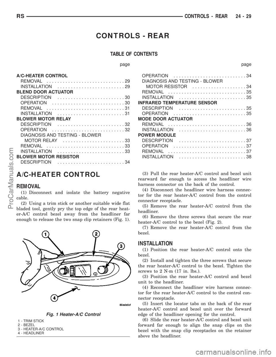
(2) Using a trim stick or another suitable wide flat
bladed tool, gently pry the top edge of the rear heat-
er-A/C control bezel away from the headliner far
enough to release the two snap clip retainers (Fig. 1).(3) Pull the rear heater-A/C control and bezel unit
rearward far enough to access the headliner wire
harness connector on the back of the control.
(4) Disconnect the headliner wire harness connec-
tor for the rear heater-A/C control from the control
connector receptacle.
(5) Remove the rear heater-A/C control from the
headliner.
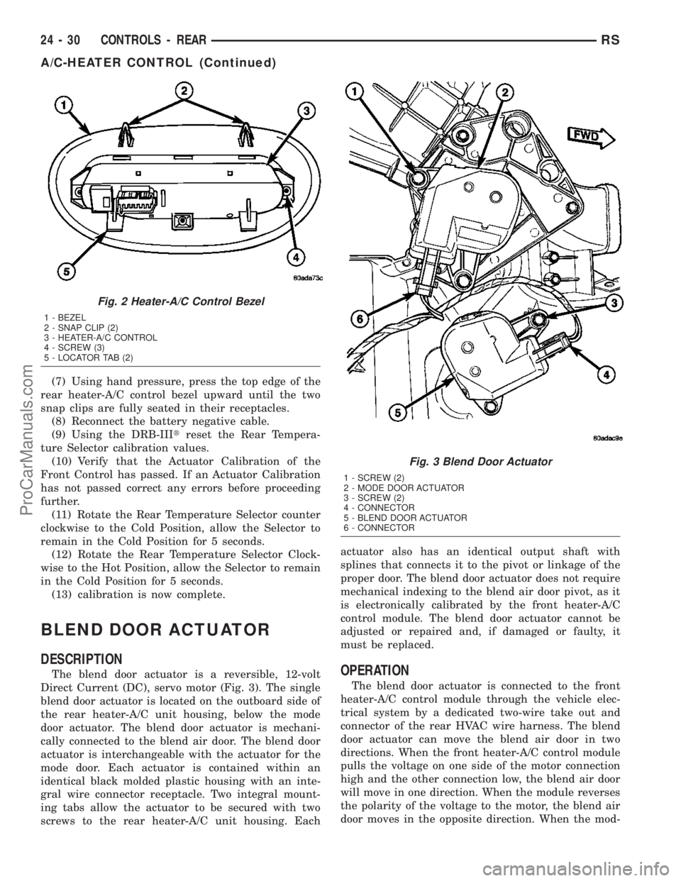
(6) Remove the three screws that secure the rear
heater-A/C control to the bezel (Fig. 2).
(7) Remove the rear heater-A/C control from the
bezel.
INSTALLATION
(1) Position the rear heater-A/C control onto the
bezel.
(2) Install and tighten the three screws that secure
the rear heater-A/C control to the bezel. Tighten the
screws to 2 N´m (17 in. lbs.).
(3) Position the rear heater-A/C control and bezel
unit to the headliner.
(4) Reconnect the headliner wire harness connec-
tor for the rear heater-A/C control to the control con-
nector receptacle.
(5) Insert the locator tabs on the back of the rear
heater-A/C control and bezel unit over the forward
edge of the headliner opening for the control.
(6) Slide the rear heater-A/C control and bezel unit
forward far enough to align the snap clips on the
bezel with the snap clip receptacles on the retainer
above the headliner.
Fig. 1 Heater-A/C Control
1 - TRIM STICK
2 - BEZEL
3 - HEATER-A/C CONTROL
4 - HEADLINER
RSCONTROLS - REAR24-29
ProCarManuals.com
Page 2027 of 2177
(7) Using hand pressure, press the top edge of the
rear heater-A/C control bezel upward until the two
snap clips are fully seated in their receptacles.
(8) Reconnect the battery negative cable.
(9) Using the DRB-IIItreset the Rear Tempera-
ture Selector calibration values.
(10) Verify that the Actuator Calibration of the
Front Control has passed. If an Actuator Calibration
has not passed correct any errors before proceeding
further.
(11) Rotate the Rear Temperature Selector counter
clockwise to the Cold Position, allow the Selector to
remain in the Cold Position for 5 seconds.
(12) Rotate the Rear Temperature Selector Clock-
wise to the Hot Position, allow the Selector to remain
in the Cold Position for 5 seconds.
(13) calibration is now complete.
BLEND DOOR ACTUATOR
DESCRIPTION
The blend door actuator is a reversible, 12-volt
Direct Current (DC), servo motor (Fig. 3). The single
blend door actuator is located on the outboard side of
the rear heater-A/C unit housing, below the mode
door actuator. The blend door actuator is mechani-
cally connected to the blend air door. The blend door
actuator is interchangeable with the actuator for the
mode door. Each actuator is contained within an
identical black molded plastic housing with an inte-
gral wire connector receptacle. Two integral mount-
ing tabs allow the actuator to be secured with two
screws to the rear heater-A/C unit housing. Eachactuator also has an identical output shaft with
splines that connects it to the pivot or linkage of the
proper door. The blend door actuator does not require
mechanical indexing to the blend air door pivot, as it
is electronically calibrated by the front heater-A/C
control module. The blend door actuator cannot be
adjusted or repaired and, if damaged or faulty, it
must be replaced.OPERATION
The blend door actuator is connected to the front
heater-A/C control module through the vehicle elec-
trical system by a dedicated two-wire take out and
connector of the rear HVAC wire harness. The blend
door actuator can move the blend air door in two
directions. When the front heater-A/C control module
pulls the voltage on one side of the motor connection
high and the other connection low, the blend air door
will move in one direction. When the module reverses
the polarity of the voltage to the motor, the blend air
door moves in the opposite direction. When the mod-
Fig. 2 Heater-A/C Control Bezel
1 - BEZEL
2 - SNAP CLIP (2)
3 - HEATER-A/C CONTROL
4 - SCREW (3)
5 - LOCATOR TAB (2)
Fig. 3 Blend Door Actuator
1 - SCREW (2)
2 - MODE DOOR ACTUATOR
3 - SCREW (2)
4 - CONNECTOR
5 - BLEND DOOR ACTUATOR
6 - CONNECTOR
24 - 30 CONTROLS - REARRS
A/C-HEATER CONTROL (Continued)
ProCarManuals.com
Page 2040 of 2177
BLOWER MOTOR
DESCRIPTION
The blower motor is a 12-volt, Direct Current (DC)
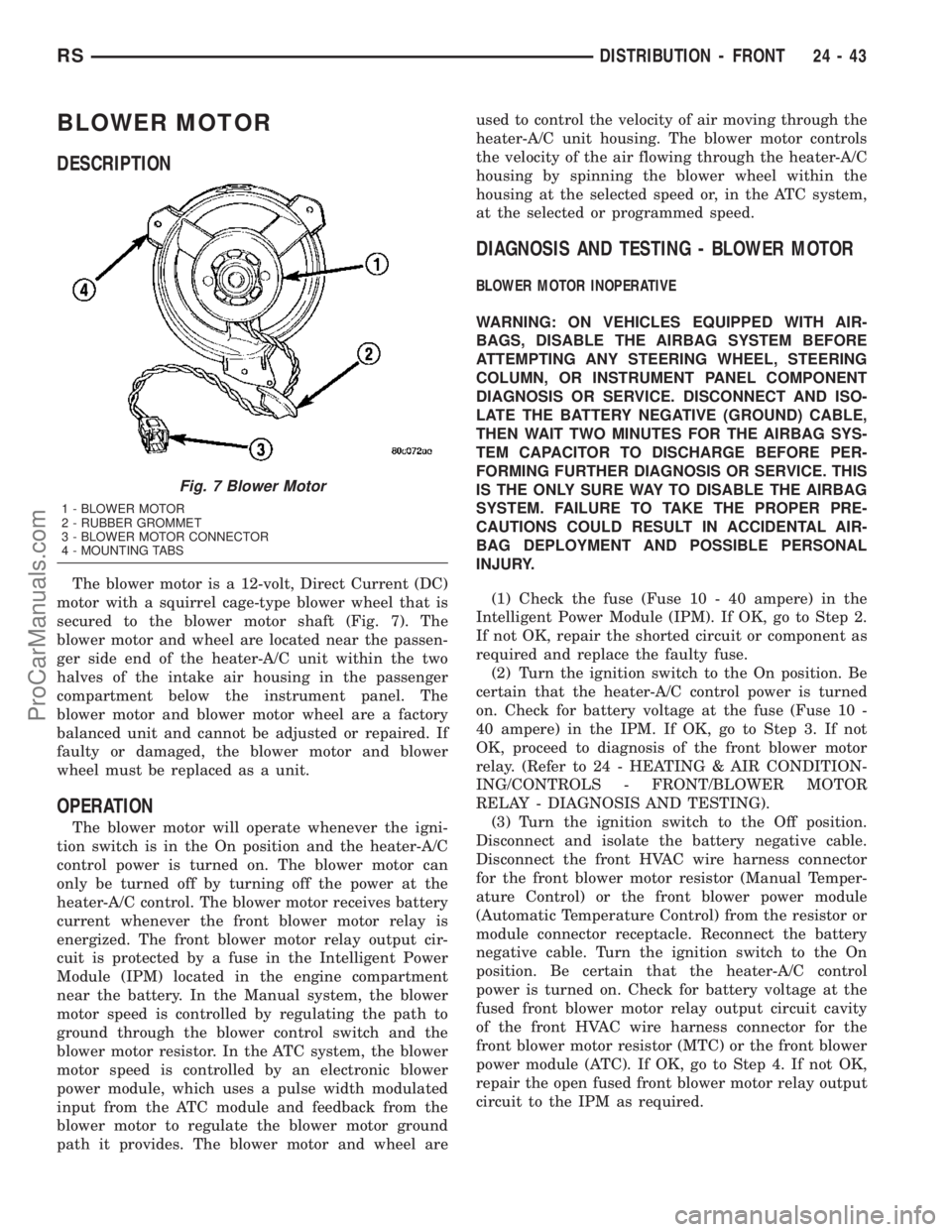
motor with a squirrel cage-type blower wheel that is
secured to the blower motor shaft (Fig. 7). The
blower motor and wheel are located near the passen-
ger side end of the heater-A/C unit within the two
halves of the intake air housing in the passenger
compartment below the instrument panel. The
blower motor and blower motor wheel are a factory
balanced unit and cannot be adjusted or repaired. If
faulty or damaged, the blower motor and blower
wheel must be replaced as a unit.
OPERATION
The blower motor will operate whenever the igni-
tion switch is in the On position and the heater-A/C
control power is turned on. The blower motor can
only be turned off by turning off the power at the
heater-A/C control. The blower motor receives battery
current whenever the front blower motor relay is
energized. The front blower motor relay output cir-
cuit is protected by a fuse in the Intelligent Power
Module (IPM) located in the engine compartment
near the battery. In the Manual system, the blower
motor speed is controlled by regulating the path to
ground through the blower control switch and the
blower motor resistor. In the ATC system, the blower
motor speed is controlled by an electronic blower
power module, which uses a pulse width modulated
input from the ATC module and feedback from the
blower motor to regulate the blower motor ground
path it provides. The blower motor and wheel areused to control the velocity of air moving through the
heater-A/C unit housing. The blower motor controls
the velocity of the air flowing through the heater-A/C
housing by spinning the blower wheel within the
housing at the selected speed or, in the ATC system,
at the selected or programmed speed.
DIAGNOSIS AND TESTING - BLOWER MOTOR
BLOWER MOTOR INOPERATIVE
WARNING: ON VEHICLES EQUIPPED WITH AIR-
BAGS, DISABLE THE AIRBAG SYSTEM BEFORE
ATTEMPTING ANY STEERING WHEEL, STEERING
COLUMN, OR INSTRUMENT PANEL COMPONENT
DIAGNOSIS OR SERVICE. DISCONNECT AND ISO-
LATE THE BATTERY NEGATIVE (GROUND) CABLE,
THEN WAIT TWO MINUTES FOR THE AIRBAG SYS-
TEM CAPACITOR TO DISCHARGE BEFORE PER-
FORMING FURTHER DIAGNOSIS OR SERVICE. THIS
IS THE ONLY SURE WAY TO DISABLE THE AIRBAG
SYSTEM. FAILURE TO TAKE THE PROPER PRE-
CAUTIONS COULD RESULT IN ACCIDENTAL AIR-
BAG DEPLOYMENT AND POSSIBLE PERSONAL
INJURY.
(1) Check the fuse (Fuse 10 - 40 ampere) in the
Intelligent Power Module (IPM). If OK, go to Step 2.
If not OK, repair the shorted circuit or component as
required and replace the faulty fuse.
(2) Turn the ignition switch to the On position. Be
certain that the heater-A/C control power is turned
on. Check for battery voltage at the fuse (Fuse 10 -
40 ampere) in the IPM. If OK, go to Step 3. If not
OK, proceed to diagnosis of the front blower motor
relay. (Refer to 24 - HEATING & AIR CONDITION-
ING/CONTROLS - FRONT/BLOWER MOTOR
RELAY - DIAGNOSIS AND TESTING).
(3) Turn the ignition switch to the Off position.
Disconnect and isolate the battery negative cable.
Disconnect the front HVAC wire harness connector
for the front blower motor resistor (Manual Temper-
ature Control) or the front blower power module
(Automatic Temperature Control) from the resistor or
module connector receptacle. Reconnect the battery
negative cable. Turn the ignition switch to the On
position. Be certain that the heater-A/C control
power is turned on. Check for battery voltage at the
fused front blower motor relay output circuit cavity
of the front HVAC wire harness connector for the
front blower motor resistor (MTC) or the front blower
power module (ATC). If OK, go to Step 4. If not OK,
repair the open fused front blower motor relay output
circuit to the IPM as required.
Fig. 7 Blower Motor
1 - BLOWER MOTOR
2 - RUBBER GROMMET
3 - BLOWER MOTOR CONNECTOR
4 - MOUNTING TABS
RSDISTRIBUTION - FRONT24-43
ProCarManuals.com
Page 2044 of 2177
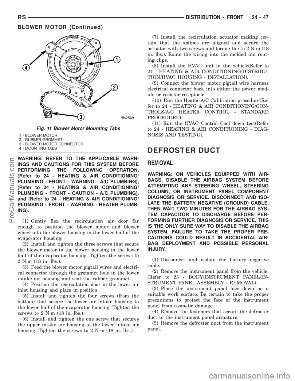
WARNING: REFER TO THE APPLICABLE WARN-
INGS AND CAUTIONS FOR THIS SYSTEM BEFORE
PERFORMING THE FOLLOWING OPERATION.
(Refer to 24 - HEATING & AIR CONDITIONING/
PLUMBING - FRONT - WARNING - A/C PLUMBING),
(Refer to 24 - HEATING & AIR CONDITIONING/
PLUMBING - FRONT - CAUTION - A/C PLUMBING),
and (Refer to 24 - HEATING & AIR CONDITIONING/
PLUMBING - FRONT - WARNING - HEATER PLUMB-
ING).
(1) Gently flex the recirculation air door far
enough to position the blower motor and blower
wheel into the blower housing in the lower half of the
evaporator housing.
(2) Install and tighten the three screws that secure
the blower motor to the blower housing in the lower
half of the evaporator housing. Tighten the screws to
2 N´m (18 in. lbs.).
(3) Feed the blower motor pigtail wires and electri-
cal connector through the grommet hole in the lower
intake air housing and seat the rubber grommet.
(4) Position the recirculation door in the lower air
inlet housing and place in position.
(5) Install and tighten the four screws (from the
bottom) that secure the lower air intake housing to
the lower half of the evaporator housing. Tighten the
screws to 2 N´m (18 in. lbs.).
(6) Install and tighten the one screw that secures
the upper intake air housing to the lower intake air
housing. Tighten the screws to 2 N´m (18 in. lbs.).(7) Install the recirculation actuator making cer-
tain that the splines are aligned and secure the
actuator with two screws and torque the to 2 N´m (18
in. lbs.). Route the wiring into the molded inn rout-
ing clips.
(8) Install the HVAC unit in the vehicle(Refer to
24 - HEATING & AIR CONDITIONING/DISTRIBU-
TION/HVAC HOUSING - INSTALLATION).
(9) Connect the blower motor pigtail wire harness
electrical connector back into either the power mod-
ule or resistor receptacle.
(10) Run the Heater-A/C Calibration procedure(Re-
fer to 24 - HEATING & AIR CONDITIONING/CON-
TROLS/A/C HEATER CONTROL - STANDARD
PROCEDURE).
(11) Run the HVAC Control Cool down test(Refer
to 24 - HEATING & AIR CONDITIONING - DIAG-
NOSIS AND TESTING).
DEFROSTER DUCT
REMOVAL
WARNING: ON VEHICLES EQUIPPED WITH AIR-
BAGS, DISABLE THE AIRBAG SYSTEM BEFORE
ATTEMPTING ANY STEERING WHEEL, STEERING
COLUMN, OR INSTRUMENT PANEL COMPONENT
DIAGNOSIS OR SERVICE. DISCONNECT AND ISO-
LATE THE BATTERY NEGATIVE (GROUND) CABLE,
THEN WAIT TWO MINUTES FOR THE AIRBAG SYS-
TEM CAPACITOR TO DISCHARGE BEFORE PER-
FORMING FURTHER DIAGNOSIS OR SERVICE. THIS
IS THE ONLY SURE WAY TO DISABLE THE AIRBAG
SYSTEM. FAILURE TO TAKE THE PROPER PRE-
CAUTIONS COULD RESULT IN ACCIDENTAL AIR-
BAG DEPLOYMENT AND POSSIBLE PERSONAL
INJURY.
(1) Disconnect and isolate the battery negative
cable.
(2) Remove the instrument panel from the vehicle.
(Refer to 23 - BODY/INSTRUMENT PANEL/IN-
STRUMENT PANEL ASSEMBLY - REMOVAL).
(3) Place the instrument panel face down on a
suitable work surface. Be certain to take the proper
precautions to protect the face of the instrument
panel from cosmetic damage.
(4) Remove the fasteners that secure the defroster
duct to the instrument panel armature.
(5) Remove the defroster duct from the instrument
panel.
Fig. 11 Blower Motor Mounting Tabs
1 - BLOWER MOTOR
2 - RUBBER GROMMET
3 - BLOWER MOTOR CONNECTOR
4 - MOUNTING TABS
RSDISTRIBUTION - FRONT24-47
BLOWER MOTOR (Continued)
ProCarManuals.com
Page 2054 of 2177
(2) Drain the engine cooling system. (Refer to 7 -
COOLING - STANDARD PROCEDURE - COOLING
SYSTEM DRAIN).
(3) Disconnect and isolate the battery negative
cable.
(4) Raise and support the vehicle.
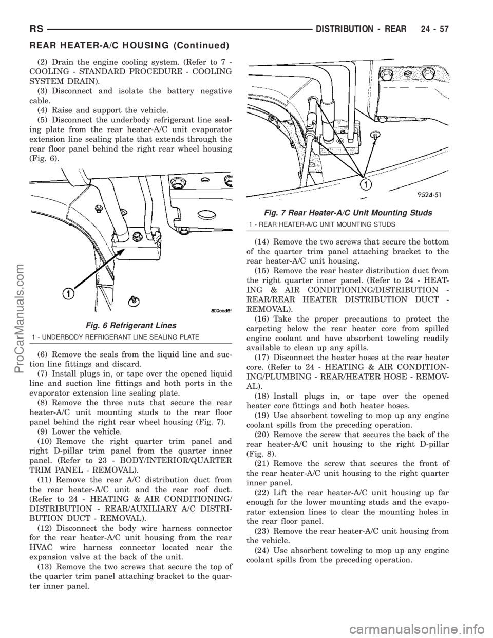
(5) Disconnect the underbody refrigerant line seal-
ing plate from the rear heater-A/C unit evaporator
extension line sealing plate that extends through the
rear floor panel behind the right rear wheel housing
(Fig. 6).
(6) Remove the seals from the liquid line and suc-
tion line fittings and discard.
(7) Install plugs in, or tape over the opened liquid
line and suction line fittings and both ports in the
evaporator extension line sealing plate.
(8) Remove the three nuts that secure the rear
heater-A/C unit mounting studs to the rear floor
panel behind the right rear wheel housing (Fig. 7).
(9) Lower the vehicle.
(10) Remove the right quarter trim panel and
right D-pillar trim panel from the quarter inner
panel. (Refer to 23 - BODY/INTERIOR/QUARTER
TRIM PANEL - REMOVAL).
(11) Remove the rear A/C distribution duct from
the rear heater-A/C unit and the rear roof duct.
(Refer to 24 - HEATING & AIR CONDITIONING/
DISTRIBUTION - REAR/AUXILIARY A/C DISTRI-
BUTION DUCT - REMOVAL).
(12) Disconnect the body wire harness connector
for the rear heater-A/C unit housing from the rear
HVAC wire harness connector located near the
expansion valve at the back of the unit.
(13) Remove the two screws that secure the top of
the quarter trim panel attaching bracket to the quar-
ter inner panel.(14) Remove the two screws that secure the bottom
of the quarter trim panel attaching bracket to the
rear heater-A/C unit housing.
(15) Remove the rear heater distribution duct from
the right quarter inner panel. (Refer to 24 - HEAT-
ING & AIR CONDITIONING/DISTRIBUTION -
REAR/REAR HEATER DISTRIBUTION DUCT -
REMOVAL).
(16) Take the proper precautions to protect the
carpeting below the rear heater core from spilled
engine coolant and have absorbent toweling readily
available to clean up any spills.
(17) Disconnect the heater hoses at the rear heater
core. (Refer to 24 - HEATING & AIR CONDITION-
ING/PLUMBING - REAR/HEATER HOSE - REMOV-
AL).
(18) Install plugs in, or tape over the opened
heater core fittings and both heater hoses.
(19) Use absorbent toweling to mop up any engine
coolant spills from the preceding operation.
(20) Remove the screw that secures the back of the
rear heater-A/C unit housing to the right D-pillar
(Fig. 8).
(21) Remove the screw that secures the front of
the rear heater-A/C unit housing to the right quarter
inner panel.
(22) Lift the rear heater-A/C unit housing up far
enough for the lower mounting studs and the evapo-
rator extension lines to clear the mounting holes in
the rear floor panel.
(23) Remove the rear heater-A/C unit housing from
the vehicle.
(24) Use absorbent toweling to mop up any engine
coolant spills from the preceding operation.
Fig. 6 Refrigerant Lines
1 - UNDERBODY REFRIGERANT LINE SEALING PLATE
Fig. 7 Rear Heater-A/C Unit Mounting Studs
1 - REAR HEATER-A/C UNIT MOUNTING STUDS
RSDISTRIBUTION - REAR24-57
REAR HEATER-A/C HOUSING (Continued)
ProCarManuals.com
Page 2059 of 2177
CAUTION: Do not use R-12 equipment or parts on
the R-134a system. Damage to the system will
result. All parts, tools, and equipment must be
designed for R-134a refrigerant.
CAUTION: Do not discharge refrigerant into the
atmosphere. Use an R-134a refrigerant recovery/re-
cycling device that meets SAE Standard J2210.
CAUTION: The refrigerant must be recovered com-
pletely from the system before opening any fitting
or connection. Open the fittings with caution, even
after the system has been discharged. If any pres-
sure is noticed as a fitting is loosened, tighten the
fitting and recover the refrigerant from the system
again.
CAUTION: The refrigerant system must always be
evacuated before charging.
CAUTION: Do not overcharge the refrigerant sys-
tem. This will cause excessive compressor head
pressure and can cause noise and system failure.
CAUTION: Do not open the refrigerant system or
remove the sealing caps from a replacement com-
ponent until it is to be installed. This will prevent
contamination in the system.
CAUTION: Before disconnecting a component,
clean the outside of the fittings thoroughly to pre-
vent contamination from entering the refrigerant
system.
CAUTION: When it is necessary to open the refrig-
erant system, have everything needed to service
the system ready. Immediately after disconnecting a
component from the refrigerant system, seal the
open fittings with a cap or plug to prevent the
entrance of dirt and moisture. The refrigerant sys-
tem should not be left open to the atmosphere any
longer than necessary.
CAUTION: Before connecting an open refrigerant
fitting, always install a new seal and or gasket. All
fittings with O-rings need to be coated with refrig-
erant oil before installation. Use only O-rings that
are the correct size and approved for use with
R-134a refrigerant. Failure to do so may result in a
leak. Coat the fitting and seal with clean refrigerant
oil before connecting. Unified plumbing connec-tions with gaskets cannot be serviced with O-rings.
The gaskets are not reusable and new gaskets do
not require lubrication before installing.
CAUTION: When installing a refrigerant line, avoid
sharp bends that may restrict refrigerant flow. A
good rule for the flexible hose refrigerant lines is to
keep the radius of all bends at least ten times the
diameter of the hose. Sharp bends will reduce the
flow of refrigerant.
CAUTION: Position the refrigerant lines away from
exhaust system components or any sharp edges,
which may damage the line. The flexible hose lines
should be routed so they are at least 80 millimeters
(3 inches) from the exhaust manifold. Inspect all
flexible refrigerant system hose lines at least once
a year to make sure they are in good condition and
properly routed.
CAUTION: High pressures are produced in the
refrigerant system when it is operating. Extreme
care must be exercised to make sure that all refrig-
erant system connections are pressure tight.
CAUTION: Tighten refrigerant fittings only to the
specified torque. The aluminum fittings used in the
refrigerant system will not tolerate overtightening.
CAUTION: When disconnecting a refrigerant fitting,
use a wrench on both halves of the fitting. This will
prevent twisting of the refrigerant lines or tubes.
CAUTION: Refrigerant oil will absorb moisture from
the atmosphere if left uncapped. Do not open a
container of refrigerant oil until you are ready to
use it. Replace the cap on the oil container immedi-
ately after using. Store refrigerant oil only in a
clean, airtight, and moisture-free container.
CAUTION: All tools, including the refrigerant recy-
cling equipment, the manifold gauge set, and test
hoses should be kept clean and dry. Keep the work
area clean. Contamination of the refrigerant system
through careless work habits must be avoided. The
refrigerant system will remain chemically stable as
long as pure, moisture-free R-134a refrigerant and
refrigerant oil is used. Dirt, moisture, or air can
upset this chemical stability. Operational troubles
or serious damage can occur if foreign material is
introduced to the refrigerant system.
24 - 62 PLUMBING - FRONTRS
PLUMBING - FRONT (Continued)
ProCarManuals.com
Page 2067 of 2177
through the evaporator tubes. The heater-A/C unit
housing must be removed from the vehicle to access
the evaporator for service. The evaporator cannot be
adjusted or repaired and, if faulty or damaged, it
must be replaced.
OPERATION
Refrigerant enters the evaporator from the expan-
sion valve as a low-temperature, low-pressure liquid/
vapor mixture. As air flows over the fins of the evap-
orator, the humidity in the air condenses on the fins,
and the heat from the air is absorbed by the refrig-
erant. Heat absorption causes the refrigerant to boil
and vaporize. The refrigerant becomes a low-pressure
gas when it leaves the evaporator.
REMOVAL
WARNING: REFER TO THE APPLICABLE WARN-
INGS AND CAUTIONS FOR THIS SYSTEM BEFORE
PERFORMING THE FOLLOWING OPERATION.
(Refer to 24 - HEATING & AIR CONDITIONING/
PLUMBING - FRONT - WARNING - A/C PLUMBING),
(Refer to 24 - HEATING & AIR CONDITIONING/
PLUMBING - FRONT - CAUTION - A/C PLUMBING),
and (Refer to 24 - HEATING & AIR CONDITIONING/
PLUMBING - FRONT - WARNING - HEATER PLUMB-
ING).
(1) Remove the HVAC unit housing from the vehi-
cle. (Refer to 24 - HEATING & AIR CONDITION-
ING/DISTRIBUTION - FRONT/HVAC HOUSING -
REMOVAL).
(2) Remove the heater core tubes from the heater
core. (Refer to 24 - HEATING & AIR CONDITION-
ING/PLUMBING - FRONT/HEATER CORE -
REMOVAL - HEATER CORE TUBES).
(3) Remove and discard the foam seal from the
HVAC housing seal flange around the fresh air inlet
opening and the expansion valve/evaporator tube
opening on the dash panel side of the unit.
(4) Remove the expansion valve from the evapora-
tor inlet and outlet tube fittings. (Refer to 24 -
HEATING & AIR CONDITIONING/PLUMBING -
FRONT/EXPANSION VALVE - REMOVAL).
(5) Disconnect the HVAC wire harness connector
for the blower motor from the motor connector recep-
tacle on the bottom of the outboard end of the evap-
orator housing.
(6) Disengage the HVAC wire harness from the
routing clips molded into the outside of the HVAC
housing components.
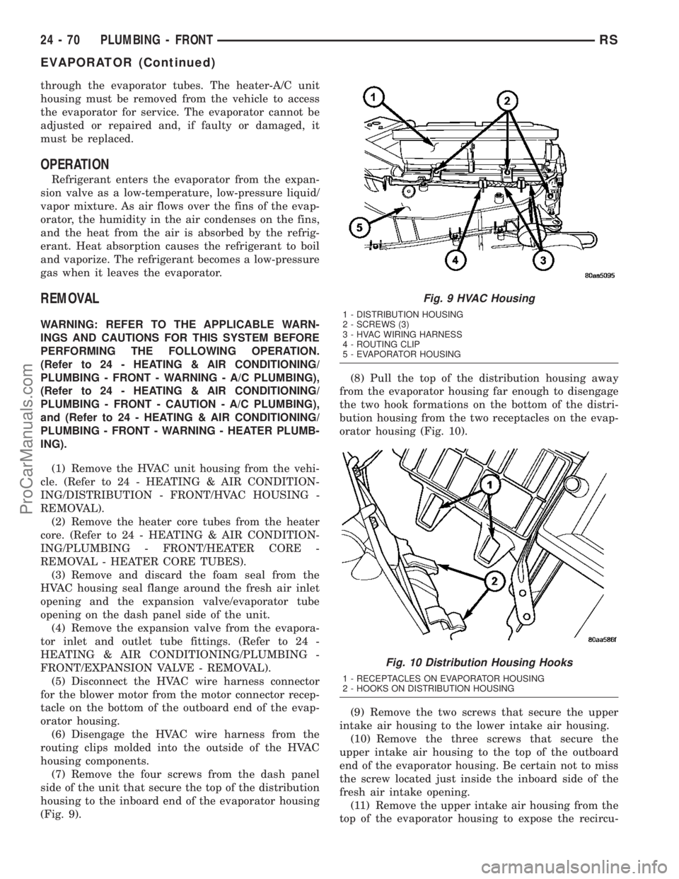
(7) Remove the four screws from the dash panel
side of the unit that secure the top of the distribution
housing to the inboard end of the evaporator housing
(Fig. 9).(8) Pull the top of the distribution housing away
from the evaporator housing far enough to disengage
the two hook formations on the bottom of the distri-
bution housing from the two receptacles on the evap-
orator housing (Fig. 10).
(9) Remove the two screws that secure the upper
intake air housing to the lower intake air housing.
(10) Remove the three screws that secure the
upper intake air housing to the top of the outboard
end of the evaporator housing. Be certain not to miss
the screw located just inside the inboard side of the
fresh air intake opening.
(11) Remove the upper intake air housing from the
top of the evaporator housing to expose the recircu-
Fig. 9 HVAC Housing
1 - DISTRIBUTION HOUSING
2 - SCREWS (3)
3 - HVAC WIRING HARNESS
4 - ROUTING CLIP
5 - EVAPORATOR HOUSING
Fig. 10 Distribution Housing Hooks
1 - RECEPTACLES ON EVAPORATOR HOUSING
2 - HOOKS ON DISTRIBUTION HOUSING
24 - 70 PLUMBING - FRONTRS
EVAPORATOR (Continued)
ProCarManuals.com