2003 CHRYSLER CARAVAN ECU
[x] Cancel search: ECUPage 1752 of 2177
INSTALLATION
NOTE: The screws attaching the door latch to the
door end frame have nylon patches on the threads.
All screws must be replaced when the latch has
been removed.
(1) Insert inside handle latch link to door latch
and engage clip (Fig. 8).
(2) Place door latch in position on door end frame.
(3) Install screws attaching door latch to door end
frame. Tighten screws to 10 N´m (90 in. lbs.) torque
(Fig. 9).
(4) Insert other linkages to door latch and engage
clips.
(5) Connect wire connector into power door lock
motor, if equipped.
(6) Insert a hex wrench through the elongated hole
located in the door shut face above the latch.
(7) Loosen allen head screw.
(8) Pull outward on the outside door handle and
release.
(9) Tighten allen head screw.
(10) Verify door latch and power door lock opera-
tion.
(11) Install watershield and front door trim panel.
LATCH STRIKER
REMOVAL
(1) Mark outline of door striker on B-pillar to aid
in installation.
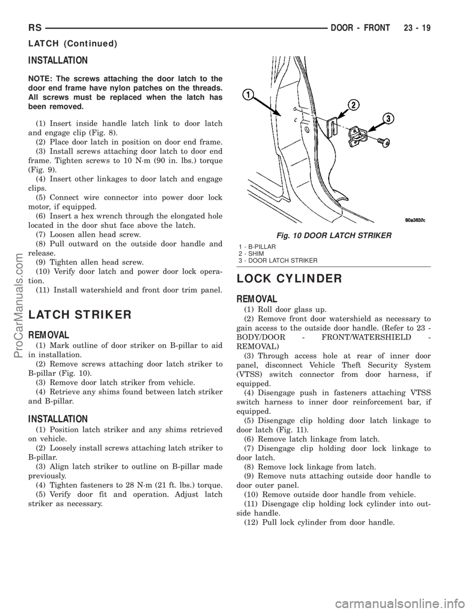
(2) Remove screws attaching door latch striker to
B-pillar (Fig. 10).
(3) Remove door latch striker from vehicle.
(4) Retrieve any shims found between latch striker
and B-pillar.
INSTALLATION
(1) Position latch striker and any shims retrieved
on vehicle.
(2) Loosely install screws attaching latch striker to
B-pillar.
(3) Align latch striker to outline on B-pillar made
previously.
(4) Tighten fasteners to 28 N´m (21 ft. lbs.) torque.
(5) Verify door fit and operation. Adjust latch
striker as necessary.
LOCK CYLINDER
REMOVAL
(1) Roll door glass up.
(2) Remove front door watershield as necessary to
gain access to the outside door handle. (Refer to 23 -
BODY/DOOR - FRONT/WATERSHIELD -
REMOVAL)
(3) Through access hole at rear of inner door
panel, disconnect Vehicle Theft Security System
(VTSS) switch connector from door harness, if
equipped.
(4) Disengage push in fasteners attaching VTSS
switch harness to inner door reinforcement bar, if
equipped.
(5) Disengage clip holding door latch linkage to
door latch (Fig. 11).
(6) Remove latch linkage from latch.
(7) Disengage clip holding door lock linkage to
door latch.
(8) Remove lock linkage from latch.
(9) Remove nuts attaching outside door handle to
door outer panel.
(10) Remove outside door handle from vehicle.
(11) Disengage clip holding lock cylinder into out-
side handle.
(12) Pull lock cylinder from door handle.
Fig. 10 DOOR LATCH STRIKER
1 - B-PILLAR
2 - SHIM
3 - DOOR LATCH STRIKER
RSDOOR - FRONT23-19
LATCH (Continued)
ProCarManuals.com
Page 1754 of 2177
(6) Install clips to attach door trim to door frame
around perimeter of panel.
(7) If equipped, install screw to attach door trim to
door panel behind inside latch release handle.
(8) If equipped, connect power switch into wire
connector.
(9) Place power accessary switch in position on
door trim.
(10) Connect wire connector into memory seat/mir-
ror switch and install switch into trim panel.
(11) Install screws to attach accessary switch
panel to door trim.
(12) Install screw cover into switch panel.
(13) If equipped, install window crank.
(14) If equipped, install screws to attach trim
panel to door inside map pocket.
(15) If equipped, install screw to attach door pull
cup to inner door panel.
(16) If equipped, install screws to attach door
assist handle to inner door panel.
(17) Connect wire connector into courtesy lamp.
(18) Install lamp in door trim.
(19) Install switch bezel.
WATERSHIELD
REMOVAL
(1) Remove door trim panel. (Refer to 23 - BODY/
DOOR - FRONT/TRIM PANEL - REMOVAL)
(2) Remove the front door speaker. (Refer to 8 -
ELECTRICAL/AUDIO/SPEAKER - REMOVAL)
(3) Peel watershield away from adhesive around
perimeter of inner door panel.
INSTALLATION
(1) Insure that enough adhesive remains to
securely retain the water dam. Replace as necessary.
(2) Place the shield into position and press
securely to adhesive making sure to properly route
wiring and linkages.
(3) Install the front door speaker. (Refer to 8 -
ELECTRICAL/AUDIO/SPEAKER - INSTALLATION)
(4) Install door trim panel. (Refer to 23 - BODY/
DOOR - FRONT/TRIM PANEL - INSTALLATION)
WINDOW CRANK
REMOVAL
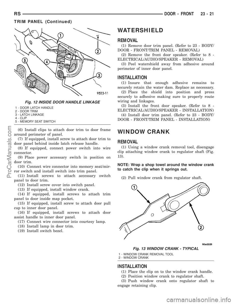
(1) Using a window crank removal tool, disengage
clip attaching window crank to regulator shaft (Fig.
13).
NOTE: Wrap a shop towel around the window crank
to catch the clip when it springs out.
(2) Pull window crank from regulator shaft.
INSTALLATION
(1) Place the clip on to the window crank handle.
(2) Position window crank to regulator shaft.
(3) Push window crank onto regulator shaft to
engage retaining clip.
Fig. 12 INSIDE DOOR HANDLE LINKAGE
1 - DOOR LATCH HANDLE
2 - DOOR TRIM
3 - LATCH LINKAGE
4 - CLIP
5 - MEMORY SEAT SWITCH
Fig. 13 WINDOW CRANK - TYPICAL
1 - WINDOW CRANK REMOVAL TOOL
2 - WINDOW CRANK
RSDOOR - FRONT23-21
TRIM PANEL (Continued)
ProCarManuals.com
Page 1755 of 2177
EXTERIOR HANDLE
REMOVAL
(1) Roll door glass up.
(2) Remove the watershield as necessary to gain
access to the outside door handle. (Refer to 23 -
BODY/DOOR - FRONT/WATERSHIELD -
REMOVAL)
(3) Through access hole at rear of inner door
panel, disconnect Vehicle Theft Security System
(VTSS) switch connector from door harness, if
equipped.
(4) Disengage push in fasteners attaching VTSS
switch harness to inner door reinforcement bar, if
equipped.
(5) Disengage clip holding door latch linkage to
door latch (Fig. 11).
(6) Remove latch linkage from latch.
(7) Disengage clip holding door lock linkage to
door latch.
(8) Remove lock linkage from latch.
(9) Remove nuts holding outside door handle to
door outer panel.
(10) Remove outside door handle from vehicle.
INSTALLATION
If outside door handle replacement is necessary,
transfer lock cylinder from the original handle to the
new one.
(1) Place outside door handle in position on vehi-
cle.
(2) Install nuts attaching outside door handle to
door outer panel (Fig. 11). Tighten nuts to 6 N´m (50
in. lbs.).
(3) Insert lock linkage into door latch.
(4) Engage clip to hold door lock linkage to latch.
(5) Insert latch linkage into door latch.
(6) Engage clip to hold door latch linkage to latch.
(7) Install push-in fasteners to hold VTSS switch
harness to inner door reinforcement bar, if equipped.
(8) Connect VTSS switch connector into door har-
ness, if equipped.
(9) Verify door latch operation.
(10) Install sound shield and door trim panel.
WINDOW REGULATOR -
POWER
REMOVAL
(1) Remove watershield. (Refer to 23 - BODY/
DOOR - FRONT/WATERSHIELD - REMOVAL)
(2) Remove inner belt molding.(Refer to 23 -
BODY/WEATHERSTRIP/SEALS/FDR INNER BELT
WEATHERSTRIP - REMOVAL)(3) Remove door glass. (Refer to 23 - BODY/DOOR
- FRONT/DOOR GLASS - REMOVAL).
(4) Disconnect wire connector from power window
motor.
(5) Loosen screws attaching front and rear window
guide rails to inner door panel.
(6) Remove screw heads on guide rails from key
hole slots in inner door panel.
(7) Loosen screws attaching motor/housing to inner
door panel.
(8) Remove regulator from inner door panel.
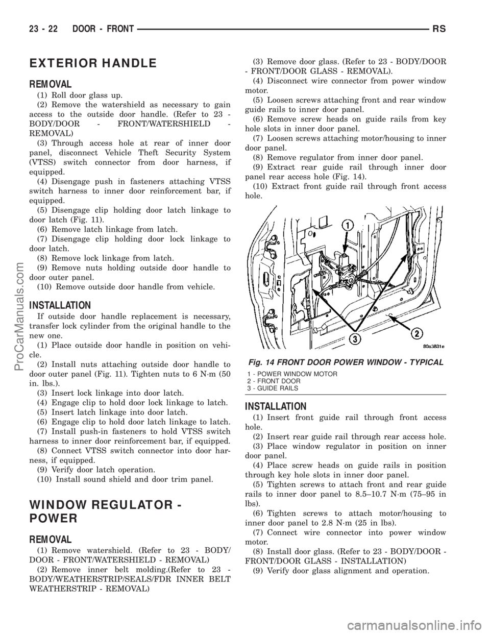
(9) Extract rear guide rail through inner door
panel rear access hole (Fig. 14).
(10) Extract front guide rail through front access
hole.
INSTALLATION
(1) Insert front guide rail through front access
hole.
(2) Insert rear guide rail through rear access hole.
(3) Place window regulator in position on inner
door panel.
(4) Place screw heads on guide rails in position
through key hole slots in inner door panel.
(5) Tighten screws to attach front and rear guide
rails to inner door panel to 8.5±10.7 N´m (75±95 in
lbs).
(6) Tighten screws to attach motor/housing to
inner door panel to 2.8 N´m (25 in lbs).
(7) Connect wire connector into power window
motor.
(8) Install door glass. (Refer to 23 - BODY/DOOR -
FRONT/DOOR GLASS - INSTALLATION)
(9) Verify door glass alignment and operation.
Fig. 14 FRONT DOOR POWER WINDOW - TYPICAL
1 - POWER WINDOW MOTOR
2 - FRONT DOOR
3 - GUIDE RAILS
23 - 22 DOOR - FRONTRS
ProCarManuals.com
Page 1760 of 2177
INSTALLATION
NOTE: For power sliding door procedures refer to
POWER SLIDING DOOR SYSTEM in the ELECTRI-
CAL section.
(1) Position latch/lock locking lever in unlocked
position.
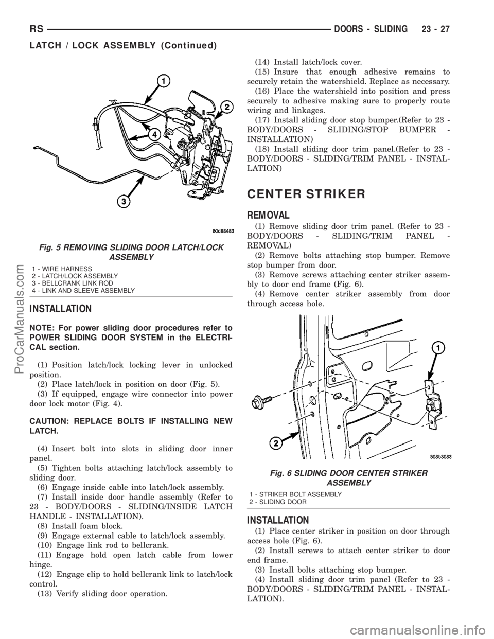
(2) Place latch/lock in position on door (Fig. 5).
(3) If equipped, engage wire connector into power
door lock motor (Fig. 4).
CAUTION: REPLACE BOLTS IF INSTALLING NEW
LATCH.
(4) Insert bolt into slots in sliding door inner
panel.
(5) Tighten bolts attaching latch/lock assembly to
sliding door.
(6) Engage inside cable into latch/lock assembly.
(7) Install inside door handle assembly (Refer to
23 - BODY/DOORS - SLIDING/INSIDE LATCH
HANDLE - INSTALLATION).
(8) Install foam block.
(9) Engage external cable to latch/lock assembly.
(10) Engage link rod to bellcrank.
(11) Engage hold open latch cable from lower
hinge.
(12) Engage clip to hold bellcrank link to latch/lock
control.
(13) Verify sliding door operation.(14) Install latch/lock cover.
(15) Insure that enough adhesive remains to
securely retain the watershield. Replace as necessary.
(16) Place the watershield into position and press
securely to adhesive making sure to properly route
wiring and linkages.
(17) Install sliding door stop bumper.(Refer to 23 -
BODY/DOORS - SLIDING/STOP BUMPER -
INSTALLATION)
(18) Install sliding door trim panel.(Refer to 23 -
BODY/DOORS - SLIDING/TRIM PANEL - INSTAL-
LATION)
CENTER STRIKER
REMOVAL
(1) Remove sliding door trim panel. (Refer to 23 -
BODY/DOORS - SLIDING/TRIM PANEL -
REMOVAL)
(2) Remove bolts attaching stop bumper. Remove
stop bumper from door.
(3) Remove screws attaching center striker assem-
bly to door end frame (Fig. 6).
(4) Remove center striker assembly from door
through access hole.
INSTALLATION
(1) Place center striker in position on door through
access hole (Fig. 6).
(2) Install screws to attach center striker to door
end frame.
(3) Install bolts attaching stop bumper.
(4) Install sliding door trim panel (Refer to 23 -
BODY/DOORS - SLIDING/TRIM PANEL - INSTAL-
LATION).
Fig. 5 REMOVING SLIDING DOOR LATCH/LOCK
ASSEMBLY
1 - WIRE HARNESS
2 - LATCH/LOCK ASSEMBLY
3 - BELLCRANK LINK ROD
4 - LINK AND SLEEVE ASSEMBLY
Fig. 6 SLIDING DOOR CENTER STRIKER
ASSEMBLY
1 - STRIKER BOLT ASSEMBLY
2 - SLIDING DOOR
RSDOORS - SLIDING23-27
LATCH / LOCK ASSEMBLY (Continued)
ProCarManuals.com
Page 1767 of 2177
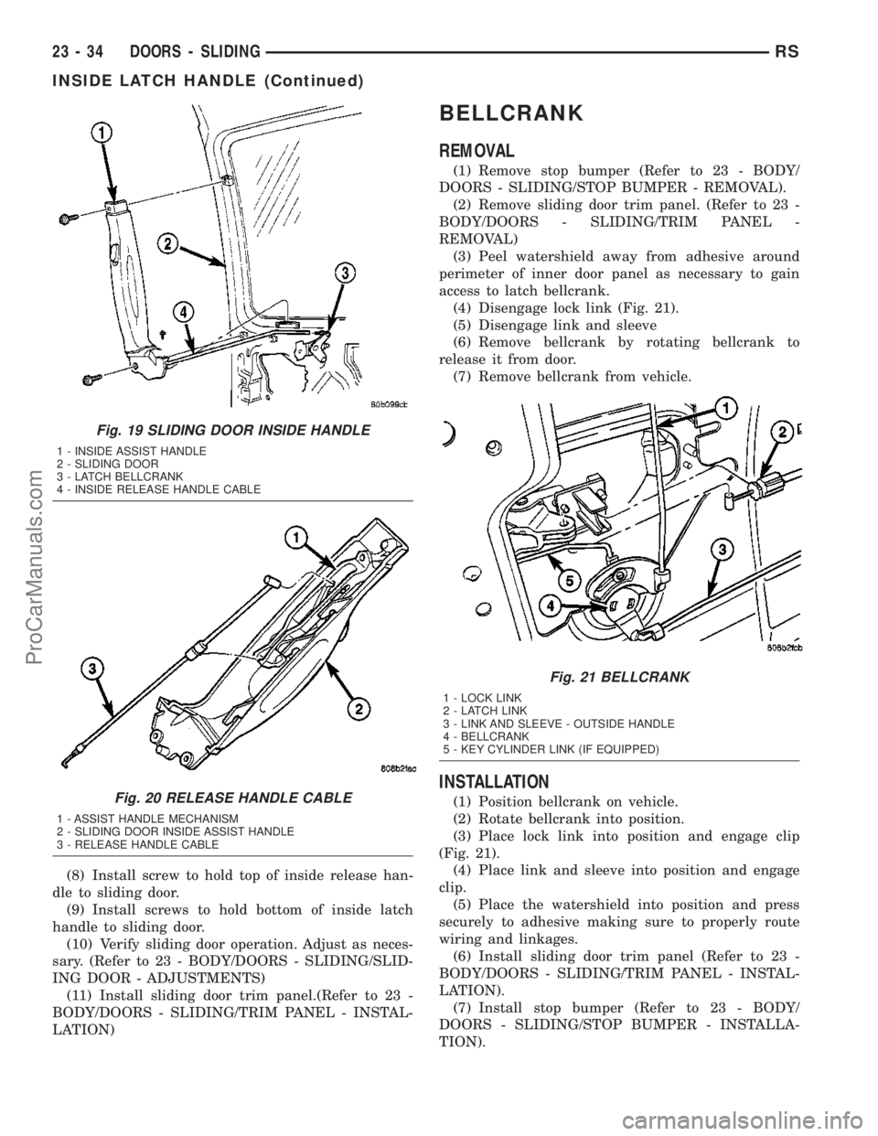
(8) Install screw to hold top of inside release han-
dle to sliding door.
(9) Install screws to hold bottom of inside latch
handle to sliding door.
(10) Verify sliding door operation. Adjust as neces-
sary. (Refer to 23 - BODY/DOORS - SLIDING/SLID-
ING DOOR - ADJUSTMENTS)
(11) Install sliding door trim panel.(Refer to 23 -
BODY/DOORS - SLIDING/TRIM PANEL - INSTAL-
LATION)
BELLCRANK
REMOVAL
(1) Remove stop bumper (Refer to 23 - BODY/
DOORS - SLIDING/STOP BUMPER - REMOVAL).
(2) Remove sliding door trim panel. (Refer to 23 -
BODY/DOORS - SLIDING/TRIM PANEL -
REMOVAL)
(3) Peel watershield away from adhesive around
perimeter of inner door panel as necessary to gain
access to latch bellcrank.
(4) Disengage lock link (Fig. 21).
(5) Disengage link and sleeve
(6) Remove bellcrank by rotating bellcrank to
release it from door.
(7) Remove bellcrank from vehicle.
INSTALLATION
(1) Position bellcrank on vehicle.
(2) Rotate bellcrank into position.
(3) Place lock link into position and engage clip
(Fig. 21).
(4) Place link and sleeve into position and engage
clip.
(5) Place the watershield into position and press
securely to adhesive making sure to properly route
wiring and linkages.
(6) Install sliding door trim panel (Refer to 23 -
BODY/DOORS - SLIDING/TRIM PANEL - INSTAL-
LATION).
(7) Install stop bumper (Refer to 23 - BODY/
DOORS - SLIDING/STOP BUMPER - INSTALLA-
TION).
Fig. 19 SLIDING DOOR INSIDE HANDLE
1 - INSIDE ASSIST HANDLE
2 - SLIDING DOOR
3 - LATCH BELLCRANK
4 - INSIDE RELEASE HANDLE CABLE
Fig. 20 RELEASE HANDLE CABLE
1 - ASSIST HANDLE MECHANISM
2 - SLIDING DOOR INSIDE ASSIST HANDLE
3 - RELEASE HANDLE CABLE
Fig. 21 BELLCRANK
1 - LOCK LINK
2 - LATCH LINK
3 - LINK AND SLEEVE - OUTSIDE HANDLE
4 - BELLCRANK
5 - KEY CYLINDER LINK (IF EQUIPPED)
23 - 34 DOORS - SLIDINGRS
INSIDE LATCH HANDLE (Continued)
ProCarManuals.com
Page 1768 of 2177
OUTSIDE HANDLE
REMOVAL
(1) Remove sliding door trim panel. (Refer to 23 -
BODY/DOORS - SLIDING/TRIM PANEL -
REMOVAL)
(2) Remove sliding door stop bumper. (Refer to 23 -
BODY/DOORS - SLIDING/STOP BUMPER -
REMOVAL)
(3) Peel watershield away from adhesive around
perimeter of inner door panel as necessary to access
outside release handle fasteners.
(4) Disengage clip attaching outside door handle
linkage to door cable.
(5) Remove linkage from outside door handle.
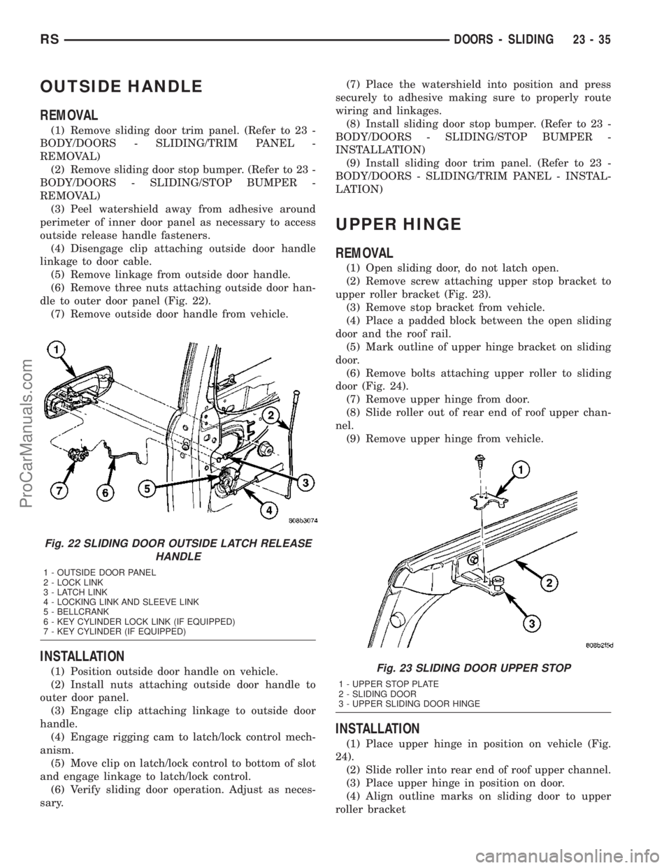
(6) Remove three nuts attaching outside door han-
dle to outer door panel (Fig. 22).
(7) Remove outside door handle from vehicle.
INSTALLATION
(1) Position outside door handle on vehicle.
(2) Install nuts attaching outside door handle to
outer door panel.
(3) Engage clip attaching linkage to outside door
handle.
(4) Engage rigging cam to latch/lock control mech-
anism.
(5) Move clip on latch/lock control to bottom of slot
and engage linkage to latch/lock control.
(6) Verify sliding door operation. Adjust as neces-
sary.(7) Place the watershield into position and press
securely to adhesive making sure to properly route
wiring and linkages.
(8) Install sliding door stop bumper. (Refer to 23 -
BODY/DOORS - SLIDING/STOP BUMPER -
INSTALLATION)
(9) Install sliding door trim panel. (Refer to 23 -
BODY/DOORS - SLIDING/TRIM PANEL - INSTAL-
LATION)
UPPER HINGE
REMOVAL
(1) Open sliding door, do not latch open.
(2) Remove screw attaching upper stop bracket to
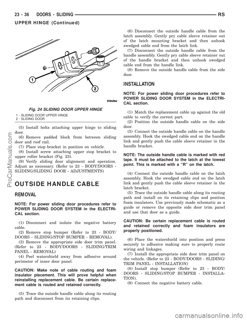
upper roller bracket (Fig. 23).
(3) Remove stop bracket from vehicle.
(4) Place a padded block between the open sliding
door and the roof rail.
(5) Mark outline of upper hinge bracket on sliding
door.
(6) Remove bolts attaching upper roller to sliding
door (Fig. 24).
(7) Remove upper hinge from door.
(8) Slide roller out of rear end of roof upper chan-
nel.
(9) Remove upper hinge from vehicle.
INSTALLATION
(1) Place upper hinge in position on vehicle (Fig.
24).
(2) Slide roller into rear end of roof upper channel.
(3) Place upper hinge in position on door.
(4) Align outline marks on sliding door to upper
roller bracket
Fig. 22 SLIDING DOOR OUTSIDE LATCH RELEASE
HANDLE
1 - OUTSIDE DOOR PANEL
2 - LOCK LINK
3 - LATCH LINK
4 - LOCKING LINK AND SLEEVE LINK
5 - BELLCRANK
6 - KEY CYLINDER LOCK LINK (IF EQUIPPED)
7 - KEY CYLINDER (IF EQUIPPED)
Fig. 23 SLIDING DOOR UPPER STOP
1 - UPPER STOP PLATE
2 - SLIDING DOOR
3 - UPPER SLIDING DOOR HINGE
RSDOORS - SLIDING23-35
ProCarManuals.com
Page 1769 of 2177
(5) Install bolts attaching upper hinge to sliding
door.
(6) Remove padded block from between sliding
door and roof rail.
(7) Place stop bracket in position on vehicle.
(8) Install screw attaching upper stop bracket to
upper roller bracket (Fig. 23).
(9) Verify sliding door alignment and operation.
Adjust as necessary. (Refer to 23 - BODY/DOORS -
SLIDING/SLIDING DOOR - ADJUSTMENTS)
OUTSIDE HANDLE CABLE
REMOVAL
NOTE: For power sliding door procedures refer to
POWER SLIDING DOOR SYSTEM in the ELECTRI-
CAL section.
(1) Disconnect and isolate the negative battery
cable.
(2) Remove stop bumper (Refer to 23 - BODY/
DOORS - SLIDING/STOP BUMPER - REMOVAL).
(3) Remove the appropriate side door trim panel.
(Refer to 23 - BODY/DOORS - SLIDING/TRIM
PANEL - REMOVAL)
(4) Peel watershield away from adhesive around
perimeter of inner door panel.
CAUTION: Make note of cable routing and foam
insulator placement. This will prove helpful when
reinstalling replacement cable. Be certain replace-
ment cable is routed and retained correctly.
(5) Trace the outside handle cable along its routing
path and disconnect from its retaining clips.(6) Disconnect the outside handle cable from the
latch assembly. Gently pry cable sleeve retainer out
of the latch mounting bracket and then unhook
swedged cable end from the latch link.
(7) Disconnect the outside handle cable from the
handle assembly. Gently pry cable sleeve retainer out
of the handle bracket and then unhook swedged
cable end from the handle link.
(8) Remove the outside handle cable from the side
door.
INSTALLATION
NOTE: For power sliding door procedures refer to
POWER SLIDING DOOR SYSTEM in the ELECTRI-
CAL section.
(1) Match the replacement cable up against the old
cable to verify the correct part.
(2) Position the outside handle cable on the side
door.
(3) Connect the outside handle cable on the handle
assembly. Hook the swedged cable end on the handle
link and gently push the cable sleeve retainer in the
handle bracket.
NOTE: The outside handle cable is marked with red
tape. It must be attached to the latch at the lowest
point. This is marked with a ªRº on the latch.
(4) Connect the outside handle cable on the latch
assembly. Hook the swedged cable end on the latch
link and gently push the cable sleeve retainer in the
latch bracket.
(5) Trace the outside handle cable along its routing
path and install on its retaining clips and position
foam insulators. Use previously made schematic as a
guide or remove the opposite side door trim panel
and use that door as a guide.
CAUTION: Be certain replacement cable is routed
and retained correctly and foam insulators are
properly positioned.
(6) Place the watershield into position and press
securely to adhesive making sure to properly route
wiring and linkages.
(7) Install the appropriate side door trim panel on
the vehicle. (Refer to 23 - BODY/DOORS - SLIDING/
TRIM PANEL - INSTALLATION)
(8) Install stop bumper (Refer to 23 - BODY/
DOORS - SLIDING/STOP BUMPER - INSTALLA-
TION).
(9) Connect the negative battery cable.
Fig. 24 SLIDING DOOR UPPER HINGE
1 - SLIDING DOOR UPPER HINGE
2 - SLIDING DOOR
23 - 36 DOORS - SLIDINGRS
UPPER HINGE (Continued)
ProCarManuals.com
Page 1770 of 2177
INSIDE HANDLE CABLE
REMOVAL
NOTE: For power sliding door procedures refer to
POWER SLIDING DOOR SYSTEM in the ELECTRI-
CAL section.
(1) Disconnect and isolate the negative battery
cable.
(2) Remove the appropriate side door trim panel
from the vehicle. (Refer to 23 - BODY/DOORS -
SLIDING/TRIM PANEL - REMOVAL)
(3) Peel watershield away from adhesive around
perimeter of inner door panel.
(4) Remove the inside handle assembly from the
side door. (Refer to 23 - BODY/DOORS - SLIDING/
INSIDE LATCH HANDLE - REMOVAL)
(5) Disconnect the inside handle cable from the
handle assembly. Gently pry cable sleeve retainer out
of the handle bracket and then unhook swedged
cable end from the handle link.
(6) Open the side door and remove the latch
assembly. Refer to the Power Side Doors section for
the procedure.
CAUTION: Make note of cable routing and foam
insulator placement. This will prove helpful when
reinstalling replacement cable. Be certain replace-
ment cable is routed and retained correctly.
(7) Trace the inside handle cable along its routing
path and disconnect from its retaining clips.
(8) Disconnect the inside handle cable from the
latch assembly. Gently pry cable sleeve retainer out
of the latch mounting bracket and then unhook
swedged cable end from the latch link.
(9) Remove the inside handle cable from the side
door.
INSTALLATION
NOTE: For power sliding door procedures refer to
POWER SLIDING DOOR SYSTEM in the ELECTRI-
CAL section.
(1) Match the replacement cable up against the old
cable to verify the correct part.
(2) Position the inside handle cable on the side
door.
(3) Connect the inside handle cable on the handle
assembly. Hook the swedged cable end on the handle
link and gently push the cable sleeve retainer in the
handle bracket.
(4) Install the inside handle assembly on the side
door. (Refer to 23 - BODY/DOORS - SLIDING/IN-
SIDE LATCH HANDLE - INSTALLATION)NOTE: The inside handle cable is marked with blue
tape and must be attached to the latch at the center
(just above the lower cable). This position is
marked with a ªBº on the latch.
(5) Connect the inside handle cable on the latch
assembly. Hook the swedged cable end on the latch
link and gently push the cable sleeve retainer in the
latch bracket.
(6) Trace the inside handle cable along its routing
path and install on its retaining clips and position
foam insulators. Use previously made schematic as a
guide or remove the opposite side door trim panel
and use that door as a guide.
CAUTION: Be certain replacement cable is routed
and retained correctly and foam insulators are
properly positioned.
(7) Install the latch assembly. Refer to the Power
Side Doors section for the procedure.
(8) Place the watershield into position and press
securely to adhesive making sure to properly route
wiring and linkages.
(9) Install the appropriate side door trim panel on
the vehicle. (Refer to 23 - BODY/DOORS - SLIDING/
TRIM PANEL - INSTALLATION)
(10) Connect the negative battery cable.
HOLD OPEN LATCH CABLE
REMOVAL
NOTE: For power sliding door procedures refer to
POWER SLIDING DOOR SYSTEM in the ELECTRI-
CAL section.
(1) Disconnect and isolate the negative battery
cable.
(2) Remove the appropriate side door trim panel
from the vehicle. (Refer to 23 - BODY/DOORS -
SLIDING/TRIM PANEL - REMOVAL)
(3) Peel watershield away from adhesive around
perimeter of inner door panel.
(4) Open the side door and remove the latch
assembly. (Refer to 8 - ELECTRICAL/POWER
DOORS/LATCH - REMOVAL)
CAUTION: Make note of cable routing and foam
insulator placement. This will prove helpful when
reinstalling replacement cable. Be certain replace-
ment cable is routed and retained correctly.
(5) Trace the hold open latch cable along its rout-
ing path and disconnect from its retaining clips.
(6) Disconnect the hold open latch cable from the
latch assembly. Gently pry cable sleeve retainer out
RSDOORS - SLIDING23-37
ProCarManuals.com