2003 CHRYSLER CARAVAN checking oil
[x] Cancel search: checking oilPage 1205 of 2177
(15) Remove cylinder head cover. (Refer to 9 -
ENGINE/CYLINDER HEAD/CYLINDER HEAD
COVER(S) - REMOVAL)
(16) Remove camshafts (Refer to 9 - ENGINE/
CYLINDER HEAD/CAMSHAFT(S) - REMOVAL).
NOTE: Identify rocker arm position to ensure cor-
rect re-installation in original position, if reused.
(17) Remove rocker arms. (Refer to 9 - ENGINE/
CYLINDER HEAD/ROCKER ARMS - REMOVAL)
(18) Remove cylinder head bolts in REVERSE
sequence of tightening (Fig. 19).
(19) Remove cylinder head from engine block.
(20) Inspect and clean cylinder head. (Refer to 9 -
ENGINE/CYLINDER HEAD - INSPECTION) (Refer
to 9 - ENGINE/CYLINDER HEAD - CLEANING)
CLEANING
To ensure engine gasket sealing, proper surface
preparation must be performed, especially with the
use of aluminum engine components and multi-layer
steel cylinder head gaskets.
NOTE: Multi-Layer Steel (MLS) head gaskets require
a scratch free sealing surface.
Remove all gasket material from cylinder head and
block (Refer to 9 - ENGINE - STANDARD PROCE-
DURE). Be careful not to gouge or scratch the alumi-
num head sealing surface.
Clean all engine oil passages.
INSPECTION
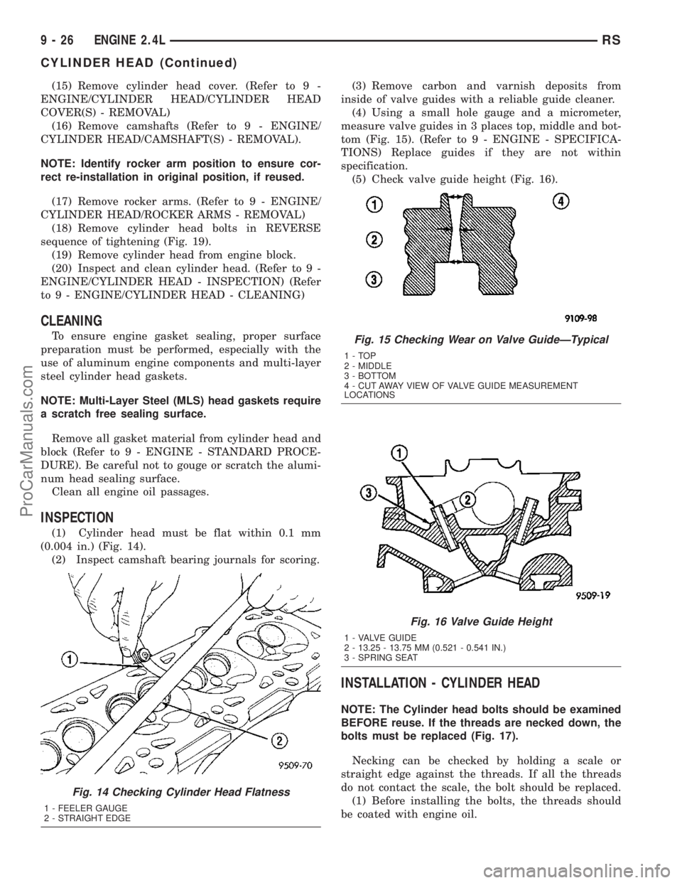
(1) Cylinder head must be flat within 0.1 mm
(0.004 in.) (Fig. 14).
(2) Inspect camshaft bearing journals for scoring.(3) Remove carbon and varnish deposits from
inside of valve guides with a reliable guide cleaner.
(4) Using a small hole gauge and a micrometer,
measure valve guides in 3 places top, middle and bot-
tom (Fig. 15). (Refer to 9 - ENGINE - SPECIFICA-
TIONS) Replace guides if they are not within
specification.
(5) Check valve guide height (Fig. 16).
INSTALLATION - CYLINDER HEAD
NOTE: The Cylinder head bolts should be examined
BEFORE reuse. If the threads are necked down, the
bolts must be replaced (Fig. 17).
Necking can be checked by holding a scale or
straight edge against the threads. If all the threads
do not contact the scale, the bolt should be replaced.
(1) Before installing the bolts, the threads should
be coated with engine oil.
Fig. 14 Checking Cylinder Head Flatness
1 - FEELER GAUGE
2 - STRAIGHT EDGE
Fig. 15 Checking Wear on Valve GuideÐTypical
1-TOP
2 - MIDDLE
3 - BOTTOM
4 - CUT AWAY VIEW OF VALVE GUIDE MEASUREMENT
LOCATIONS
Fig. 16 Valve Guide Height
1 - VALVE GUIDE
2 - 13.25 - 13.75 MM (0.521 - 0.541 IN.)
3 - SPRING SEAT
9 - 26 ENGINE 2.4LRS
CYLINDER HEAD (Continued)
ProCarManuals.com
Page 1206 of 2177
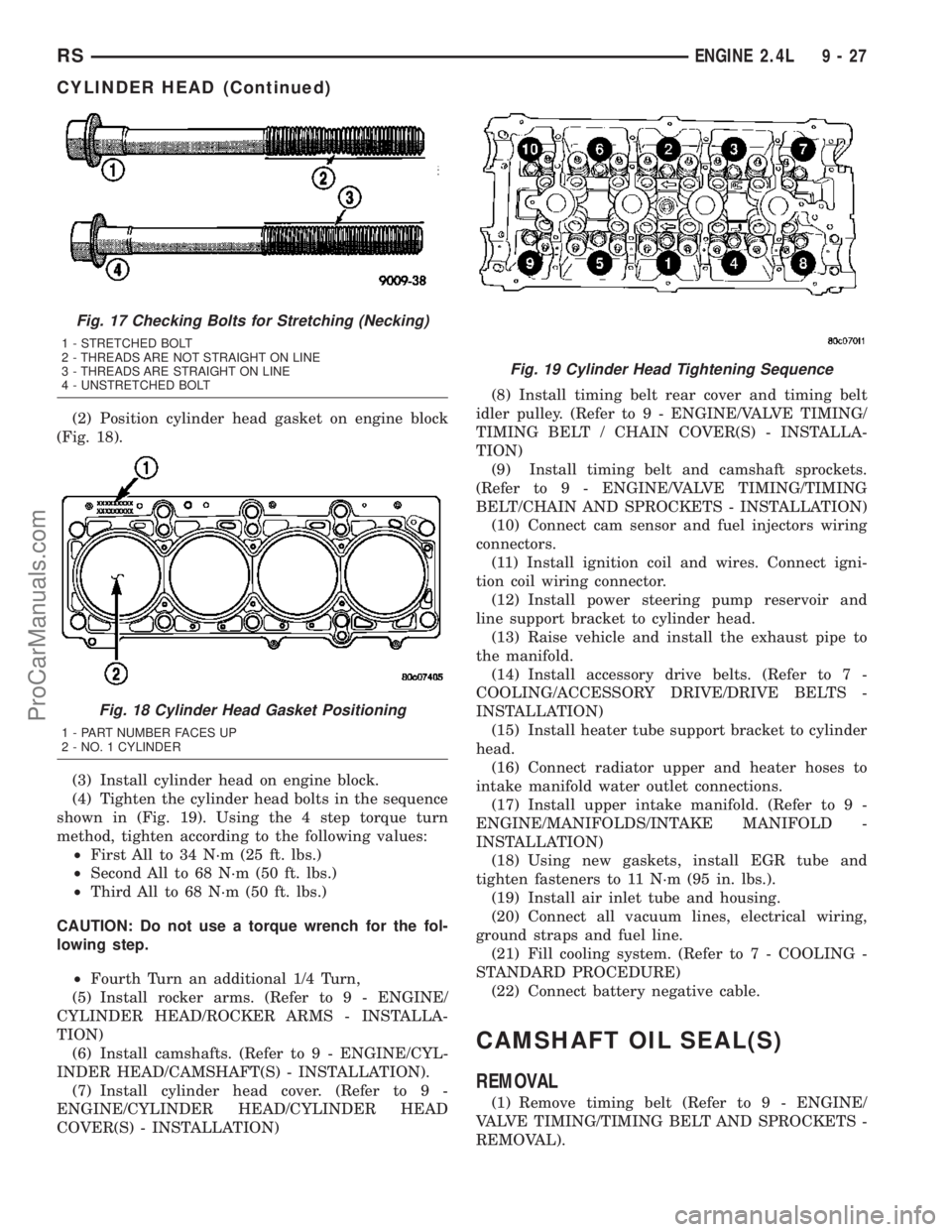
(2) Position cylinder head gasket on engine block
(Fig. 18).
(3) Install cylinder head on engine block.
(4) Tighten the cylinder head bolts in the sequence
shown in (Fig. 19). Using the 4 step torque turn
method, tighten according to the following values:
²First All to 34 N´m (25 ft. lbs.)
²Second All to 68 N´m (50 ft. lbs.)
²Third All to 68 N´m (50 ft. lbs.)
CAUTION: Do not use a torque wrench for the fol-
lowing step.
²Fourth Turn an additional 1/4 Turn,
(5) Install rocker arms. (Refer to 9 - ENGINE/
CYLINDER HEAD/ROCKER ARMS - INSTALLA-
TION)
(6) Install camshafts. (Refer to 9 - ENGINE/CYL-
INDER HEAD/CAMSHAFT(S) - INSTALLATION).
(7) Install cylinder head cover. (Refer to 9 -
ENGINE/CYLINDER HEAD/CYLINDER HEAD
COVER(S) - INSTALLATION)(8) Install timing belt rear cover and timing belt
idler pulley. (Refer to 9 - ENGINE/VALVE TIMING/
TIMING BELT / CHAIN COVER(S) - INSTALLA-
TION)
(9) Install timing belt and camshaft sprockets.
(Refer to 9 - ENGINE/VALVE TIMING/TIMING
BELT/CHAIN AND SPROCKETS - INSTALLATION)
(10) Connect cam sensor and fuel injectors wiring
connectors.
(11) Install ignition coil and wires. Connect igni-
tion coil wiring connector.
(12) Install power steering pump reservoir and
line support bracket to cylinder head.
(13) Raise vehicle and install the exhaust pipe to
the manifold.
(14) Install accessory drive belts. (Refer to 7 -
COOLING/ACCESSORY DRIVE/DRIVE BELTS -
INSTALLATION)
(15) Install heater tube support bracket to cylinder
head.
(16) Connect radiator upper and heater hoses to
intake manifold water outlet connections.
(17) Install upper intake manifold. (Refer to 9 -
ENGINE/MANIFOLDS/INTAKE MANIFOLD -
INSTALLATION)
(18) Using new gaskets, install EGR tube and
tighten fasteners to 11 N´m (95 in. lbs.).
(19) Install air inlet tube and housing.
(20) Connect all vacuum lines, electrical wiring,
ground straps and fuel line.
(21) Fill cooling system. (Refer to 7 - COOLING -
STANDARD PROCEDURE)
(22) Connect battery negative cable.
CAMSHAFT OIL SEAL(S)
REMOVAL
(1) Remove timing belt (Refer to 9 - ENGINE/
VALVE TIMING/TIMING BELT AND SPROCKETS -
REMOVAL).
Fig. 17 Checking Bolts for Stretching (Necking)
1 - STRETCHED BOLT
2 - THREADS ARE NOT STRAIGHT ON LINE
3 - THREADS ARE STRAIGHT ON LINE
4 - UNSTRETCHED BOLT
Fig. 18 Cylinder Head Gasket Positioning
1 - PART NUMBER FACES UP
2 - NO. 1 CYLINDER
Fig. 19 Cylinder Head Tightening Sequence
RSENGINE 2.4L9-27
CYLINDER HEAD (Continued)
ProCarManuals.com
Page 1209 of 2177
INSPECTION
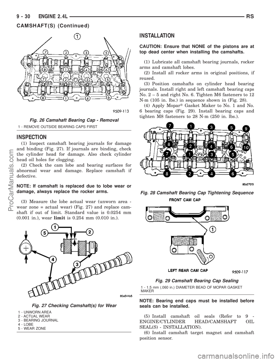
(1) Inspect camshaft bearing journals for damage
and binding (Fig. 27). If journals are binding, check
the cylinder head for damage. Also check cylinder
head oil holes for clogging.
(2) Check the cam lobe and bearing surfaces for
abnormal wear and damage. Replace camshaft if
defective.
NOTE: If camshaft is replaced due to lobe wear or
damage, always replace the rocker arms.
(3) Measure the lobe actual wear (unworn area -
wear zone = actual wear) (Fig. 27) and replace cam-
shaft if out of limit. Standard value is 0.0254 mm
(0.001 in.), wearlimitis 0.254 mm (0.010 in.).
INSTALLATION
CAUTION: Ensure that NONE of the pistons are at
top dead center when installing the camshafts.
(1) Lubricate all camshaft bearing journals, rocker
arms and camshaft lobes.
(2) Install all rocker arms in original positions, if
reused.
(3) Position camshafts on cylinder head bearing
journals. Install right and left camshaft bearing caps
No.2±5andright No. 6. Tighten M6 fasteners to 12
N´m (105 in. lbs.) in sequence shown in (Fig. 28).
(4) Apply MopartGasket Maker to No. 1 and No.
6 bearing caps (Fig. 29). Install bearing caps and
tighten M8 fasteners to 28 N´m (250 in. lbs.).
NOTE: Bearing end caps must be installed before
seals can be installed.
(5) Install camshaft oil seals (Refer to 9 -
ENGINE/CYLINDER HEAD/CAMSHAFT OIL
SEAL(S) - INSTALLATION).
(6) Install camshaft target magnet and camshaft
position sensor.
Fig. 26 Camshaft Bearing Cap - Removal
1 - REMOVE OUTSIDE BEARING CAPS FIRST
Fig. 27 Checking Camshaft(s) for Wear
1 - UNWORN AREA
2 - ACTUAL WEAR
3 - BEARING JOURNAL
4 - LOBE
5 - WEAR ZONE
Fig. 28 Camshaft Bearing Cap Tightening Sequence
Fig. 29 Camshaft Bearing Cap Sealing
1 - 1.5 mm (.060 in.) DIAMETER BEAD OF MOPAR GASKET
MAKER
9 - 30 ENGINE 2.4LRS
CAMSHAFT(S) (Continued)
ProCarManuals.com
Page 1212 of 2177
INSTALLATION
INSTALLATION - CYLINDER HEAD ON
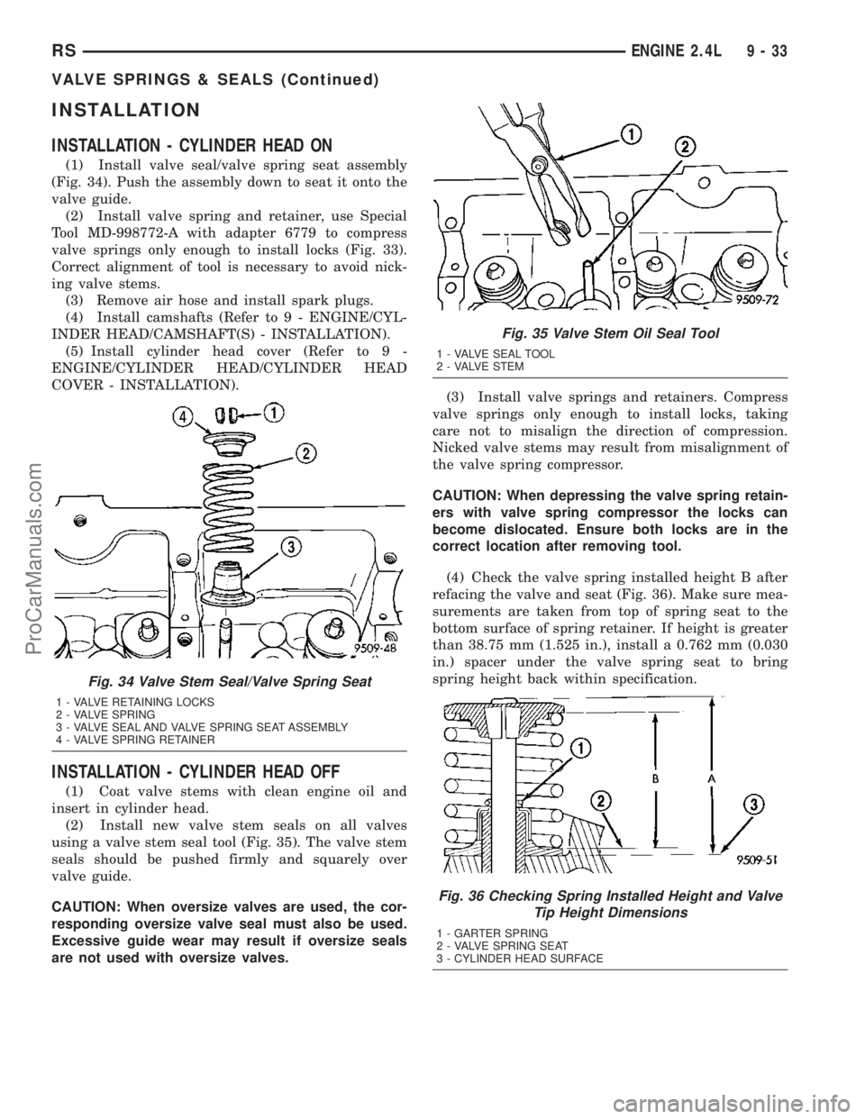
(1) Install valve seal/valve spring seat assembly
(Fig. 34). Push the assembly down to seat it onto the
valve guide.
(2) Install valve spring and retainer, use Special
Tool MD-998772-A with adapter 6779 to compress
valve springs only enough to install locks (Fig. 33).
Correct alignment of tool is necessary to avoid nick-
ing valve stems.
(3) Remove air hose and install spark plugs.
(4) Install camshafts (Refer to 9 - ENGINE/CYL-
INDER HEAD/CAMSHAFT(S) - INSTALLATION).
(5) Install cylinder head cover (Refer to 9 -
ENGINE/CYLINDER HEAD/CYLINDER HEAD
COVER - INSTALLATION).
INSTALLATION - CYLINDER HEAD OFF
(1) Coat valve stems with clean engine oil and
insert in cylinder head.
(2) Install new valve stem seals on all valves
using a valve stem seal tool (Fig. 35). The valve stem
seals should be pushed firmly and squarely over
valve guide.
CAUTION: When oversize valves are used, the cor-
responding oversize valve seal must also be used.
Excessive guide wear may result if oversize seals
are not used with oversize valves.(3) Install valve springs and retainers. Compress
valve springs only enough to install locks, taking
care not to misalign the direction of compression.
Nicked valve stems may result from misalignment of
the valve spring compressor.
CAUTION: When depressing the valve spring retain-
ers with valve spring compressor the locks can
become dislocated. Ensure both locks are in the
correct location after removing tool.
(4) Check the valve spring installed height B after
refacing the valve and seat (Fig. 36). Make sure mea-
surements are taken from top of spring seat to the
bottom surface of spring retainer. If height is greater
than 38.75 mm (1.525 in.), install a 0.762 mm (0.030
in.) spacer under the valve spring seat to bring
spring height back within specification.
Fig. 34 Valve Stem Seal/Valve Spring Seat
1 - VALVE RETAINING LOCKS
2 - VALVE SPRING
3 - VALVE SEAL AND VALVE SPRING SEAT ASSEMBLY
4 - VALVE SPRING RETAINER
Fig. 35 Valve Stem Oil Seal Tool
1 - VALVE SEAL TOOL
2 - VALVE STEM
Fig. 36 Checking Spring Installed Height and Valve
Tip Height Dimensions
1 - GARTER SPRING
2 - VALVE SPRING SEAT
3 - CYLINDER HEAD SURFACE
RSENGINE 2.4L9-33
VALVE SPRINGS & SEALS (Continued)
ProCarManuals.com
Page 1215 of 2177

(4) A controlled hone motor speed between
200±300 RPM is necessary to obtain the proper cross-
hatch angle. The number of up and down strokes per
minute can be regulated to get the desired 40±60
degree angle. Faster up and down strokes increase
the cross-hatch angle.
(5) After honing, it is necessary that the block be
cleaned again to remove all traces of abrasive.
CAUTION: Ensure all abrasives are removed from
engine parts after honing. It is recommended that a
solution of soap and hot water be used with a
brush and the parts then thoroughly dried. The bore
can be considered clean when it can be wiped
clean with a white cloth and cloth remains clean.
Oil the bores after cleaning to prevent rusting.
CLEANING
Clean cylinder block thoroughly using a suitable
cleaning solvent.
INSPECTION
ENGINE BLOCK
(1) Clean cylinder block thoroughly and check all
core hole plugs for evidence of leaking.
(2) If new core plugs are to be installed, (Refer to 9
- ENGINE - STANDARD PROCEDURE - ENGINE
CORE AND OIL GALLERY PLUGS).
(3) Examine block and cylinder bores for cracks or
fractures.(4) Check block deck surfaces for flatness. Deck
surface must be within service limit of 0.1 mm (0.004
in.).
CYLINDER BORE
NOTE: The cylinder bores should be measured at
normal room temperature, 21ÉC (70ÉF).
The cylinder walls should be checked for out-of-
round and taper with Tool C119 or equivalent (Fig.
42) (Refer to 9 - ENGINE - SPECIFICATIONS). If
the cylinder walls are badly scuffed or scored, the
cylinder block should be replaced, and new pistons
and rings fitted.
Measure the cylinder bore at three levels in direc-
tions A and B (Fig. 42). Top measurement should be
10 mm (3/8 in.) down and bottom measurement
should be 10 mm (3/8 in.) up from bottom of bore.
(Refer to 9 - ENGINE - SPECIFICATIONS).
CRANKSHAFT
STANDARD PROCEDURE - CRANKSHAFT END
PLAY
(1) Using Dial Indicator C-3339 and Mounting
Post L-4438, attach to front of engine, locating probe
perpendicular on nose of crankshaft (Fig. 43).
(2) Move crankshaft all the way to the rear of its
travel.
(3) Zero the dial indicator.
Fig. 41 Cylinder Bore Cross-Hatch Pattern
1 - CROSS-HATCH PATTERN
2 - 40ɱ60É
Fig. 42 Checking Cylinder Bore Size
9 - 36 ENGINE 2.4LRS
ENGINE BLOCK (Continued)
ProCarManuals.com
Page 1216 of 2177
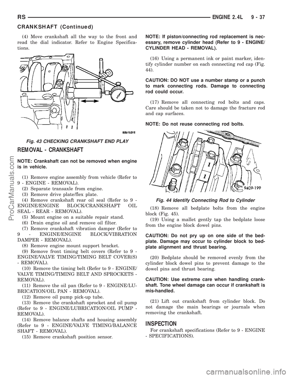
(4) Move crankshaft all the way to the front and
read the dial indicator. Refer to Engine Specifica-
tions.
REMOVAL - CRANKSHAFT
NOTE: Crankshaft can not be removed when engine
is in vehicle.
(1) Remove engine assembly from vehicle (Refer to
9 - ENGINE - REMOVAL).
(2) Separate transaxle from engine.
(3) Remove drive plate/flex plate.
(4) Remove crankshaft rear oil seal (Refer to 9 -
ENGINE/ENGINE BLOCK/CRANKSHAFT OIL
SEAL - REAR - REMOVAL).
(5) Mount engine on a suitable repair stand.
(6) Drain engine oil and remove oil filter.
(7) Remove crankshaft vibration damper (Refer to
9 - ENGINE/ENGINE BLOCK/VIBRATION
DAMPER - REMOVAL).
(8) Remove engine mount support bracket.
(9) Remove front timing belt covers (Refer to 9 -
ENGINE/VALVE TIMING/TIMING BELT COVER(S)
- REMOVAL).
(10) Remove the timing belt (Refer to 9 - ENGINE/
VALVE TIMING/TIMING BELT AND SPROCKETS -
REMOVAL).
(11) Remove the oil pan (Refer to 9 - ENGINE/LU-
BRICATION/OIL PAN - REMOVAL).
(12) Remove oil pump pick-up tube.
(13) Remove the crankshaft sprocket and oil pump
(Refer to 9 - ENGINE/LUBRICATION/OIL PUMP -
REMOVAL).
(14) Remove balance shafts and housing assembly
(Refer to 9 - ENGINE/VALVE TIMING/BALANCE
SHAFT - REMOVAL).
(15) Remove crankshaft position sensor.NOTE: If piston/connecting rod replacement is nec-
essary, remove cylinder head (Refer to 9 - ENGINE/
CYLINDER HEAD - REMOVAL).
(16) Using a permanent ink or paint marker, iden-
tify cylinder number on each connecting rod cap (Fig.
44).
CAUTION: DO NOT use a number stamp or a punch
to mark connecting rods. Damage to connecting
rod could occur.
(17) Remove all connecting rod bolts and caps.
Care should be taken not to damage the fracture rod
and cap surfaces.
NOTE: Do not reuse connecting rod bolts.
(18) Remove all bedplate bolts from the engine
block (Fig. 45).
(19) Using a mallet gently tap the bedplate loose
from the engine block dowel pins.
CAUTION: Do not pry up on one side of the bed-
plate. Damage may occur to cylinder block to bed-
plate alignment and thrust bearing.
(20) Bedplate should be removed evenly from the
cylinder block dowel pins to prevent damage to the
dowel pins and thrust bearing.
CAUTION: Use extreme care when handling crank-
shaft. Tone wheel damage can occur if crankshaft is
mis-handled.
(21) Lift out crankshaft from cylinder block. Do
not damage the main bearings or journals when
removing the crankshaft.
INSPECTION
For crankshaft specifications (Refer to 9 - ENGINE
- SPECIFICATIONS).
Fig. 43 CHECKING CRANKSHAFT END PLAY
Fig. 44 Identify Connecting Rod to Cylinder
RSENGINE 2.4L9-37
CRANKSHAFT (Continued)
ProCarManuals.com
Page 1222 of 2177
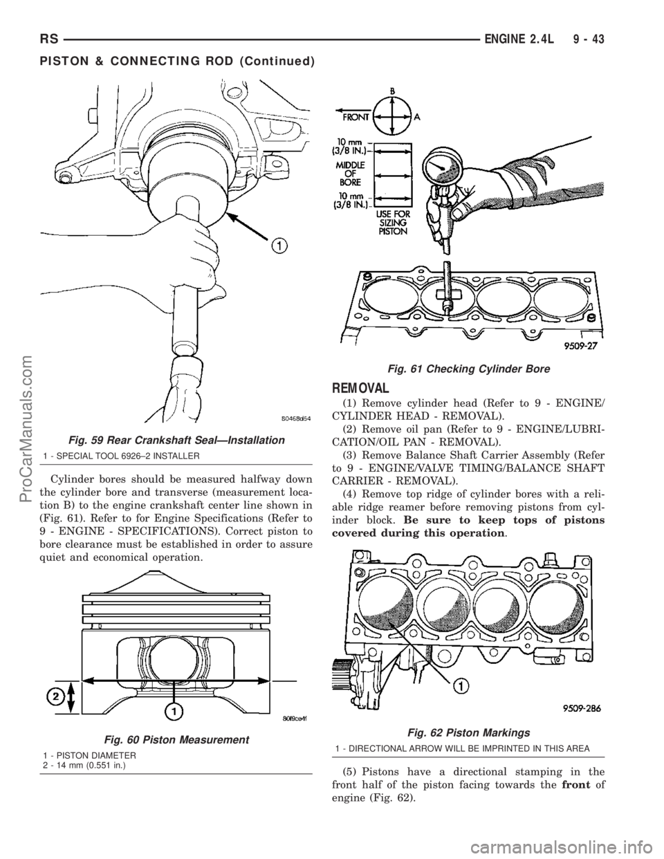
Cylinder bores should be measured halfway down
the cylinder bore and transverse (measurement loca-
tion B) to the engine crankshaft center line shown in
(Fig. 61). Refer to for Engine Specifications (Refer to
9 - ENGINE - SPECIFICATIONS). Correct piston to
bore clearance must be established in order to assure
quiet and economical operation.
REMOVAL
(1) Remove cylinder head (Refer to 9 - ENGINE/
CYLINDER HEAD - REMOVAL).
(2) Remove oil pan (Refer to 9 - ENGINE/LUBRI-
CATION/OIL PAN - REMOVAL).
(3) Remove Balance Shaft Carrier Assembly (Refer
to 9 - ENGINE/VALVE TIMING/BALANCE SHAFT
CARRIER - REMOVAL).
(4) Remove top ridge of cylinder bores with a reli-
able ridge reamer before removing pistons from cyl-
inder block.Be sure to keep tops of pistons
covered during this operation.
(5) Pistons have a directional stamping in the
front half of the piston facing towards thefrontof
engine (Fig. 62).
Fig. 59 Rear Crankshaft SealÐInstallation
1 - SPECIAL TOOL 6926±2 INSTALLER
Fig. 60 Piston Measurement
1 - PISTON DIAMETER
2 - 14 mm (0.551 in.)
Fig. 61 Checking Cylinder Bore
Fig. 62 Piston Markings
1 - DIRECTIONAL ARROW WILL BE IMPRINTED IN THIS AREA
RSENGINE 2.4L9-43
PISTON & CONNECTING ROD (Continued)
ProCarManuals.com
Page 1231 of 2177
LUBRICATION
DESCRIPTION
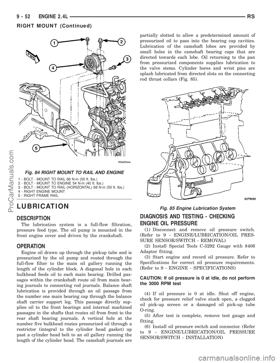
The lubrication system is a full-flow filtration,
pressure feed type. The oil pump is mounted in the
front engine cover and driven by the crankshaft.
OPERATION
Engine oil drawn up through the pickup tube and is
pressurized by the oil pump and routed through the
full-flow filter to the main oil gallery running the
length of the cylinder block. A diagonal hole in each
bulkhead feeds oil to each main bearing. Drilled pas-
sages within the crankshaft route oil from main bear-
ing journals to connecting rod journals. Balance shaft
lubrication is provided through an oil passage from
the number one main bearing cap through the balance
shaft carrier support leg. This passage directly sup-
plies oil to the front bearings and internal machined
passages in the shafts that routes oil from front to the
rear shaft bearing journals. A vertical hole at the
number five bulkhead routes pressurized oil through a
restrictor (integral to the cylinder head gasket) up
past a cylinder head bolt to an oil gallery running the
length of the cylinder head. The camshaft journals arepartially slotted to allow a predetermined amount of
pressurized oil to pass into the bearing cap cavities.
Lubrication of the camshaft lobes are provided by
small holes in the camshaft bearing caps that are
directed towards each lobe. Oil returning to the pan
from pressurized components supplies lubrication to
the valve stems. Cylinder bores and wrist pins are
splash lubricated from directed slots on the connecting
rod thrust collars (Fig. 85).
DIAGNOSIS AND TESTING - CHECKING
ENGINE OIL PRESSURE
(1) Disconnect and remove oil pressure switch.
(Refer to 9 - ENGINE/LUBRICATION/OIL PRES-
SURE SENSOR/SWITCH - REMOVAL)
(2) Install Special Tools C-3292 Gauge with 8406
Adaptor fitting.
(3) Start engine and record oil pressure. Refer to
Specifications for correct oil pressure requirements.
(Refer to 9 - ENGINE - SPECIFICATIONS)
CAUTION: If oil pressure is 0 at idle, do not perform
the 3000 RPM test
(4) If oil pressure is 0 at idle. Shut off engine,
check for pressure relief valve stuck open, a clogged
oil pick-up screen or a damaged oil pick-up tube
O-ring.
(5) After test is complete, remove test gauge and
fitting.
(6) Install oil pressure switch and connector. (Refer
to 9 - ENGINE/LUBRICATION/OIL PRESSURE
SENSOR/SWITCH - INSTALLATION)
Fig. 84 RIGHT MOUNT TO RAIL AND ENGINE
1 - BOLT - MOUNT TO RAIL 68 N´m (50 ft. lbs.)
2 - BOLT - MOUNT TO ENGINE 54 N´m (40 ft. lbs.)
3 - BOLT - MOUNT TO RAIL (HORIZONTAL) 68 N´m (50 ft. lbs.)
4 - RIGHT ENGINE MOUNT
5 - RIGHT FRAME RAIL
Fig. 85 Engine Lubrication System
9 - 52 ENGINE 2.4LRS
RIGHT MOUNT (Continued)
ProCarManuals.com