Page 1448 of 2177
TRANSMISSION/TRANSAXLE
TABLE OF CONTENTS
page page
POWER TRANSFER UNIT..................1
T850 MANUAL TRANSAXLE...............2141TE AUTOMATIC TRANSAXLE............116
POWER TRANSFER UNIT
TABLE OF CONTENTS
page page
POWER TRANSFER UNIT
DESCRIPTION..........................1
OPERATION............................3
DIAGNOSIS AND TESTING
SEAL IDENTIFICATION..................3
FLUID LEAK DIAGNOSIS................3
STANDARD PROCEDURE
STANDARD PROCEDURE - FLUID LEVEL
INSPECTION..........................4
STANDARD PROCEDURE - PTU FLUID
CHANGE.............................5
REMOVAL.............................5
INSTALLATION..........................6
ADJUSTMENTS
OUTPUT FLANGE SHIM SELECTION.......7
SPECIFICATIONS
TORQUE.............................7
SPECIAL TOOLS
SDP POWER TRANSFER UNIT............8
DIFFERENTIAL CARRIER SEAL
REMOVAL.............................9
INSTALLATION..........................9
END COVER BALL BEARING
REMOVAL.............................9INSTALLATION.........................10
END COVER SEAL
REMOVAL.............................11
INSTALLATION.........................11
HALF SHAFT INNER SEAL
REMOVAL.............................12
INSTALLATION.........................12
INPUT SHAFT COVER SEAL
REMOVAL.............................13
INSTALLATION.........................14
INPUT SHAFT END SEAL
REMOVAL.............................15
INSTALLATION.........................16
INPUT SHAFT SEAL
REMOVAL.............................17
INSTALLATION.........................18
OUTER HALF SHAFT SEAL
REMOVAL.............................19
INSTALLATION.........................19
REAR COVER O-RING
REMOVAL.............................19
INSTALLATION.........................20
POWER TRANSFER UNIT
DESCRIPTION
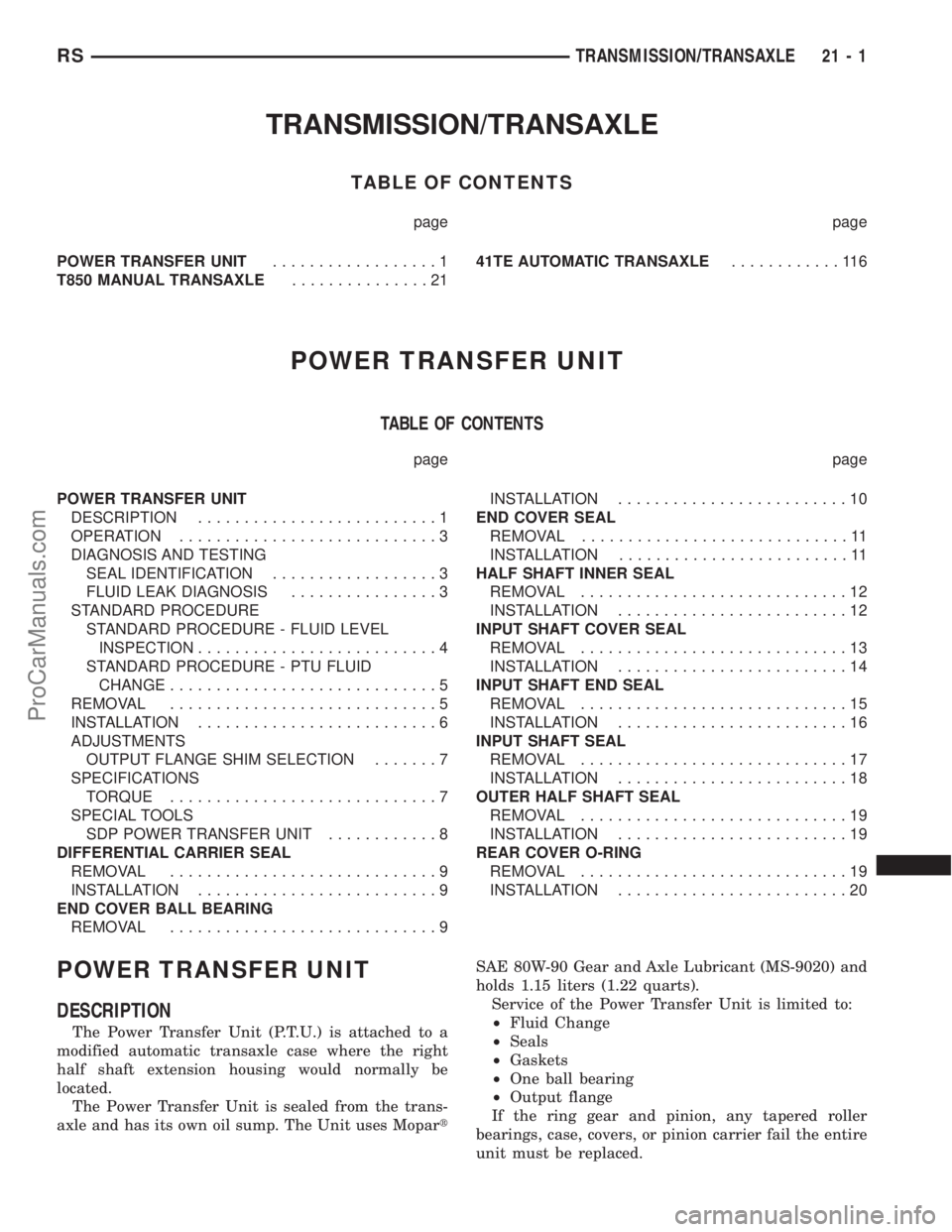
The Power Transfer Unit (P.T.U.) is attached to a
modified automatic transaxle case where the right
half shaft extension housing would normally be
located.
The Power Transfer Unit is sealed from the trans-
axle and has its own oil sump. The Unit uses MopartSAE 80W-90 Gear and Axle Lubricant (MS-9020) and
holds 1.15 liters (1.22 quarts).
Service of the Power Transfer Unit is limited to:
²Fluid Change
²Seals
²Gaskets
²One ball bearing
²Output flange
If the ring gear and pinion, any tapered roller
bearings, case, covers, or pinion carrier fail the entire
unit must be replaced.
RSTRANSMISSION/TRANSAXLE21-1
ProCarManuals.com
Page 1450 of 2177
OPERATION
The Transfer Unit provides the power to the rear
wheels through a hypoid ring gear and pinion set.
DIAGNOSIS AND TESTING
SEAL IDENTIFICATION
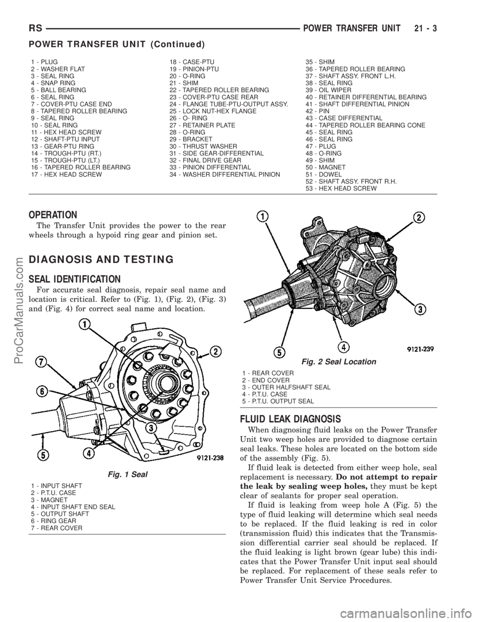
For accurate seal diagnosis, repair seal name and
location is critical. Refer to (Fig. 1), (Fig. 2), (Fig. 3)
and (Fig. 4) for correct seal name and location.
FLUID LEAK DIAGNOSIS
When diagnosing fluid leaks on the Power Transfer
Unit two weep holes are provided to diagnose certain
seal leaks. These holes are located on the bottom side
of the assembly (Fig. 5).
If fluid leak is detected from either weep hole, seal
replacement is necessary.Do not attempt to repair
the leak by sealing weep holes,they must be kept
clear of sealants for proper seal operation.
If fluid is leaking from weep hole A (Fig. 5) the
type of fluid leaking will determine which seal needs
to be replaced. If the fluid leaking is red in color
(transmission fluid) this indicates that the Transmis-
sion differential carrier seal should be replaced. If
the fluid leaking is light brown (gear lube) this indi-
cates that the Power Transfer Unit input seal should
be replaced. For replacement of these seals refer to
Power Transfer Unit Service Procedures.
1 - PLUG 18 - CASE-PTU 35 - SHIM
2 - WASHER FLAT 19 - PINION-PTU 36 - TAPERED ROLLER BEARING
3 - SEAL RING 20 - O-RING 37 - SHAFT ASSY. FRONT L.H.
4 - SNAP RING 21 - SHIM 38 - SEAL RING
5 - BALL BEARING 22 - TAPERED ROLLER BEARING 39 - OIL WIPER
6 - SEAL RING 23 - COVER-PTU CASE REAR 40 - RETAINER DIFFERENTIAL BEARING
7 - COVER-PTU CASE END 24 - FLANGE TUBE-PTU-OUTPUT ASSY. 41 - SHAFT DIFFERENTIAL PINION
8 - TAPERED ROLLER BEARING 25 - LOCK NUT-HEX FLANGE 42 - PIN
9 - SEAL RING 26 - O- RING 43 - CASE DIFFERENTIAL
10 - SEAL RING 27 - RETAINER PLATE 44 - TAPERED ROLLER BEARING CONE
11 - HEX HEAD SCREW 28 - O-RING 45 - SEAL RING
12 - SHAFT-PTU INPUT 29 - BRACKET 46 - SEAL RING
13 - GEAR-PTU RING 30 - THRUST WASHER 47 - PLUG
14 - TROUGH-PTU (RT.) 31 - SIDE GEAR-DIFFERENTIAL 48 - O-RING
15 - TROUGH-PTU (LT.) 32 - FINAL DRIVE GEAR 49 - SHIM
16 - TAPERED ROLLER BEARING 33 - PINION DIFFERENTIAL 50 - MAGNET
17 - HEX HEAD SCREW 34 - WASHER DIFFERENTIAL PINION 51 - DOWEL
52 - SHAFT ASSY. FRONT R.H.
53 - HEX HEAD SCREW
Fig. 1 Seal
1 - INPUT SHAFT
2 - P.T.U. CASE
3 - MAGNET
4 - INPUT SHAFT END SEAL
5 - OUTPUT SHAFT
6 - RING GEAR
7 - REAR COVER
Fig. 2 Seal Location
1 - REAR COVER
2 - END COVER
3 - OUTER HALFSHAFT SEAL
4 - P.T.U. CASE
5 - P.T.U. OUTPUT SEAL
RSPOWER TRANSFER UNIT21-3
POWER TRANSFER UNIT (Continued)
ProCarManuals.com
Page 1458 of 2177
END COVER SEAL
REMOVAL
The Power Transfer Unit must be removed from
the vehicle to perform this operation. (Refer to 21 -
TRANSMISSION/TRANSAXLE/POWER TRANSFER
UNIT - REMOVAL)
(1) Remove P.T.U. end cover bolts (Fig. 22).
(2) Gently tap on end cover ears with a hammer to
separate end cover from the case (Fig. 23).
(3) Clean and inspect sealer surfaces.
INSTALLATION
(1) Reinstall cover and tighten bolts to 28 N´m
(250 in. lbs.) in the sequence shown in (Fig. 24).
Retighten first bolt after all others are tight.
CAUTION: When end cover is installed be careful
not to damage the P.T.U. Input Shaft Cover Seal.
(2) Reinstall P.T.U. into vehicle.
(3) Check and fill fluids as required.
Fig. 22 P.T.U. End Cover Bolts
1 - POWER TRANSFER UNIT
2 - FILL PLUG
3 - END COVER
4 - OUTPUT SHAFT
Fig. 23 End Cover Removal
1 - END COVER EARS
2 - HAMMER
3 - POWER TRANSFER UNIT
Fig. 24 Bolt Tightening Sequence
RSPOWER TRANSFER UNIT21-11
ProCarManuals.com
Page 1479 of 2177
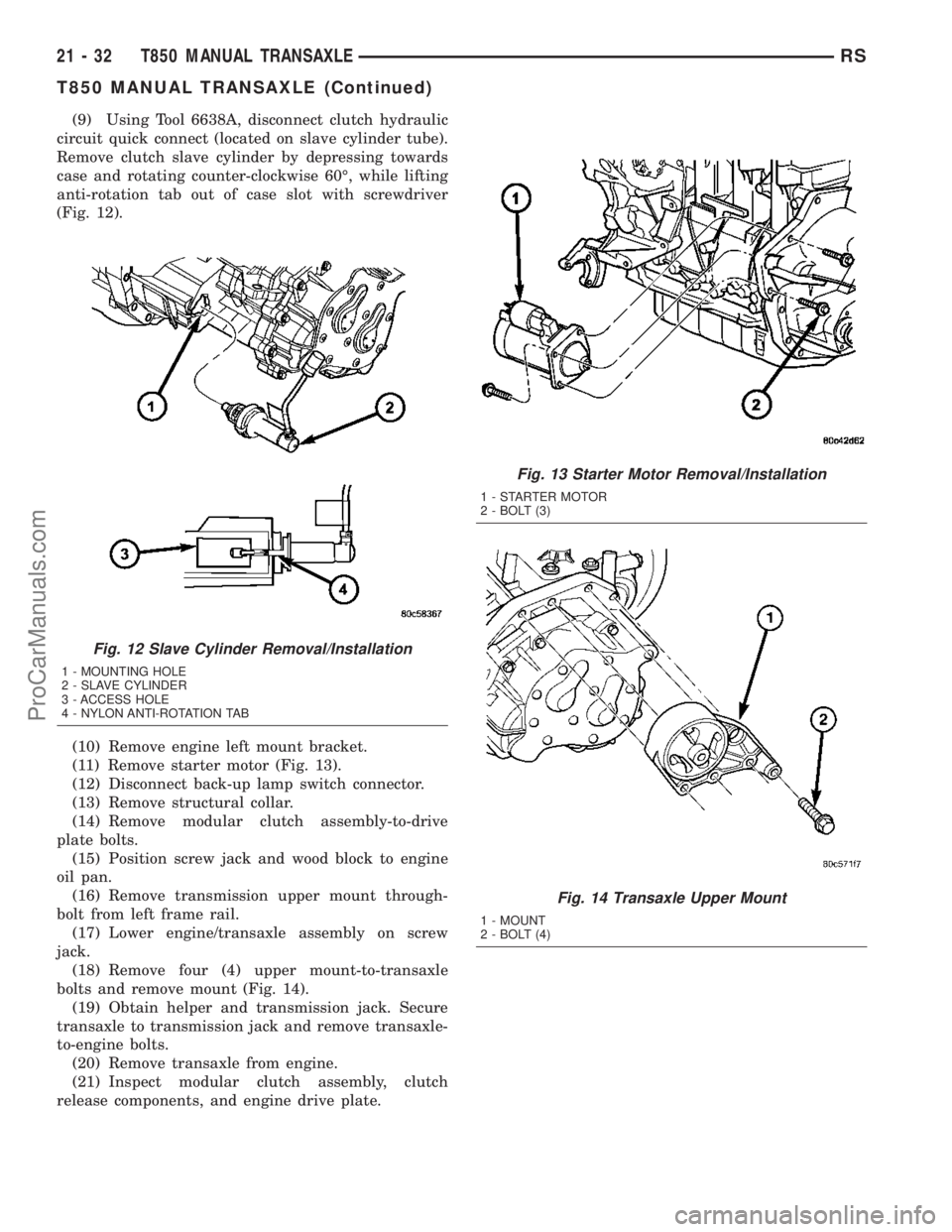
(9) Using Tool 6638A, disconnect clutch hydraulic
circuit quick connect (located on slave cylinder tube).
Remove clutch slave cylinder by depressing towards
case and rotating counter-clockwise 60É, while lifting
anti-rotation tab out of case slot with screwdriver
(Fig. 12).
(10) Remove engine left mount bracket.
(11) Remove starter motor (Fig. 13).
(12) Disconnect back-up lamp switch connector.
(13) Remove structural collar.
(14) Remove modular clutch assembly-to-drive
plate bolts.
(15) Position screw jack and wood block to engine
oil pan.
(16) Remove transmission upper mount through-
bolt from left frame rail.
(17) Lower engine/transaxle assembly on screw
jack.
(18) Remove four (4) upper mount-to-transaxle
bolts and remove mount (Fig. 14).
(19) Obtain helper and transmission jack. Secure
transaxle to transmission jack and remove transaxle-
to-engine bolts.
(20) Remove transaxle from engine.
(21) Inspect modular clutch assembly, clutch
release components, and engine drive plate.
Fig. 12 Slave Cylinder Removal/Installation
1 - MOUNTING HOLE
2 - SLAVE CYLINDER
3 - ACCESS HOLE
4 - NYLON ANTI-ROTATION TAB
Fig. 13 Starter Motor Removal/Installation
1 - STARTER MOTOR
2 - BOLT (3)
Fig. 14 Transaxle Upper Mount
1 - MOUNT
2 - BOLT (4)
21 - 32 T850 MANUAL TRANSAXLERS
T850 MANUAL TRANSAXLE (Continued)
ProCarManuals.com
Page 1481 of 2177
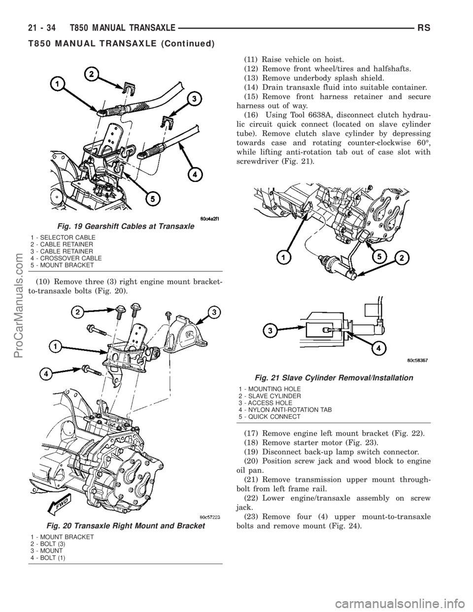
(10) Remove three (3) right engine mount bracket-
to-transaxle bolts (Fig. 20).(11) Raise vehicle on hoist.
(12) Remove front wheel/tires and halfshafts.
(13) Remove underbody splash shield.
(14) Drain transaxle fluid into suitable container.
(15) Remove front harness retainer and secure
harness out of way.
(16) Using Tool 6638A, disconnect clutch hydrau-
lic circuit quick connect (located on slave cylinder
tube). Remove clutch slave cylinder by depressing
towards case and rotating counter-clockwise 60É,
while lifting anti-rotation tab out of case slot with
screwdriver (Fig. 21).
(17) Remove engine left mount bracket (Fig. 22).
(18) Remove starter motor (Fig. 23).
(19) Disconnect back-up lamp switch connector.
(20) Position screw jack and wood block to engine
oil pan.
(21) Remove transmission upper mount through-
bolt from left frame rail.
(22) Lower engine/transaxle assembly on screw
jack.
(23) Remove four (4) upper mount-to-transaxle
bolts and remove mount (Fig. 24).
Fig. 19 Gearshift Cables at Transaxle
1 - SELECTOR CABLE
2 - CABLE RETAINER
3 - CABLE RETAINER
4 - CROSSOVER CABLE
5 - MOUNT BRACKET
Fig. 20 Transaxle Right Mount and Bracket
1 - MOUNT BRACKET
2 - BOLT (3)
3 - MOUNT
4 - BOLT (1)
Fig. 21 Slave Cylinder Removal/Installation
1 - MOUNTING HOLE
2 - SLAVE CYLINDER
3 - ACCESS HOLE
4 - NYLON ANTI-ROTATION TAB
5 - QUICK CONNECT
21 - 34 T850 MANUAL TRANSAXLERS
T850 MANUAL TRANSAXLE (Continued)
ProCarManuals.com
Page 1482 of 2177
(24) Obtain helper and transmission jack. Secure
transaxle to transmission jack and remove transaxle-
to-engine bolts.
(25) Remove transaxle from engine (Fig. 25).
(26) Inspect clutch, clutch release components, and
flywheel.
DISASSEMBLY
(1) Remove clutch release lever and bearing (Fig.
26). Inspect release lever pivot balls and replace if
necessary (Fig. 27). Use slide hammer C-3752 and
remover/installer 6891 (Fig. 28) if pivot ball replace-
ment is necessary.
Fig. 22 Left Mount Bracket Removal/Installation
1 - BOLT (2)
2 - MOUNT BRACKET
3 - BOLT (2)
Fig. 23 Starter Motor Removal/Installation
1 - STARTER MOTOR
2 - BOLT (3)
Fig. 24 Transaxle Upper Mount
1 - MOUNT
2 - BOLT (4)
RST850 MANUAL TRANSAXLE21-35
T850 MANUAL TRANSAXLE (Continued)
ProCarManuals.com
Page 1487 of 2177
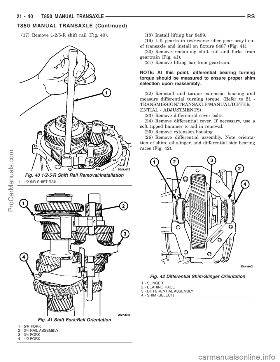
(17) Remove 1-2/5-R shift rail (Fig. 40). (18) Install lifting bar 8489.
(19) Lift geartrain (w/reverse idler gear assy.) out
of transaxle and install on fixture 8487 (Fig. 41).
(20) Remove remaining shift rail and forks from
geartrain (Fig. 41).
(21) Remove lifting bar from geartrain.
NOTE: At this point, differential bearing turning
torque should be measured to ensure proper shim
selection upon reassembly.
(22) Reinstall and torque extension housing and
measure differential turning torque. (Refer to 21 -
TRANSMISSION/TRANSAXLE/MANUAL/DIFFER-
ENTIAL - ADJUSTMENTS)
(23) Remove differential cover bolts.
(24) Remove differential cover. If necessary, use a
soft tipped hammer to aid in removal.
(25) Remove extension housing.
(26) Remove differential assembly. Note orienta-
tion of shim, oil slinger, and differential side bearing
races (Fig. 42).
Fig. 40 1/2-5/R Shift Rail Removal/Installation
1 - 1/2-5/R SHIFT RAIL
Fig. 41 Shift Fork/Rail Orientation
1 - 5/R FORK
2 - 3/4 RAIL ASSEMBLY
3 - 3/4 FORK
4 - 1/2 FORK
Fig. 42 Differential Shim/Slinger Orientation
1 - SLINGER
2 - BEARING RACE
3 - DIFFERENTIAL ASSEMBLY
4 - SHIM (SELECT)
21 - 40 T850 MANUAL TRANSAXLERS
T850 MANUAL TRANSAXLE (Continued)
ProCarManuals.com
Page 1489 of 2177
ASSEMBLY
NOTE: When assembling this transaxle, always use
NEW snap rings.
NOTE: Before assembling transaxle, differential
turning torque must be measured and adjusted.
(Refer to 21 - TRANSMISSION/TRANSAXLE/MANU-
AL/DIFFERENTIAL - ADJUSTMENTS). Differential
turning torque must be measured with geartrain out
of case.
(1) Install input shaft bearing using an arbor press
and remover/installer 8474 (Fig. 47).
(2) Install shift shaft bushing to case using
installer 8475 (Fig. 48).
Fig. 46 Input Shaft Bearing Removal
1 - ARBOR PRESS
2 - DRIVER HANDLE C-4171
3 - REMOVER/INSTALLER 8474
Fig. 47 Input Shaft Bearing Installation
1 - ARBOR PRESS
2 - C-4171 DRIVER HANDLE
3 - REMOVER/INSTALLER 8474
4 - INPUT SHAFT BEARING
Fig. 48 Shift Shaft Bushing Installation
1 - INSTALLER 8475
2 - SHIFT SHAFT BUSHING
21 - 42 T850 MANUAL TRANSAXLERS
T850 MANUAL TRANSAXLE (Continued)
ProCarManuals.com