2003 CHRYSLER CARAVAN manual transmission
[x] Cancel search: manual transmissionPage 1362 of 2177
nect rubber fuel fill or vent hoses from tank at this
time.
(7) Place a transmission jack under center of fuel
tank. Apply a slight amount of pressure to fuel tank
with transmission jack.
(8) Remove fuel tank mounting strap nuts from
mounting strap studs.
(9)Lower the tank just enough so that the
filler tube fitting is the highest point of the fuel
tank.
(10) Remove filler tube from fuel tank. Tank will
be drained through this fitting.
WARNING: WRAP SHOP TOWELS AROUND HOSES
TO CATCH ANY GASOLINE SPILLAGE.(11) Drain fuel tank into holding tank or a prop-
erly labeledGasolinesafety container.
CAUTION: GASOLINE OR GASOLINE VAPORS ARE
HIGHLY FLAMMABLE. A FIRE COULD OCCUR IF AN
IGNITION SOURCE IS PRESENT. NEVER DRAIN OR
STORE GASOLINE OR DIESEL FUEL IN AN OPEN
CONTAINER, DUE TO THE POSSIBILITY OF FIRE
OR EXPLOSION.
(12) If fuel pump module removal is necessary,
refer to Fuel Pump Module Removal/Installation in
this section.
SPECIFICATIONS
FUEL SYSTEM PRESSURE
400 kpa 34 kpa (58 psi 5 psi)
TORQUE
DESCRIPTION N´m Ft. Lbs. In. Lbs.
Fuel Filler Neck Clamp 3.3 30
Fuel Rail 2.4L 22 200
Fuel Rail 3.3/3.8L 11.8 105
Fuel Tank Strap 54 40
Fuel Tank T Strap 28.2 250
Fuel Filter Bolt 4.5 40
SPECIAL TOOLS
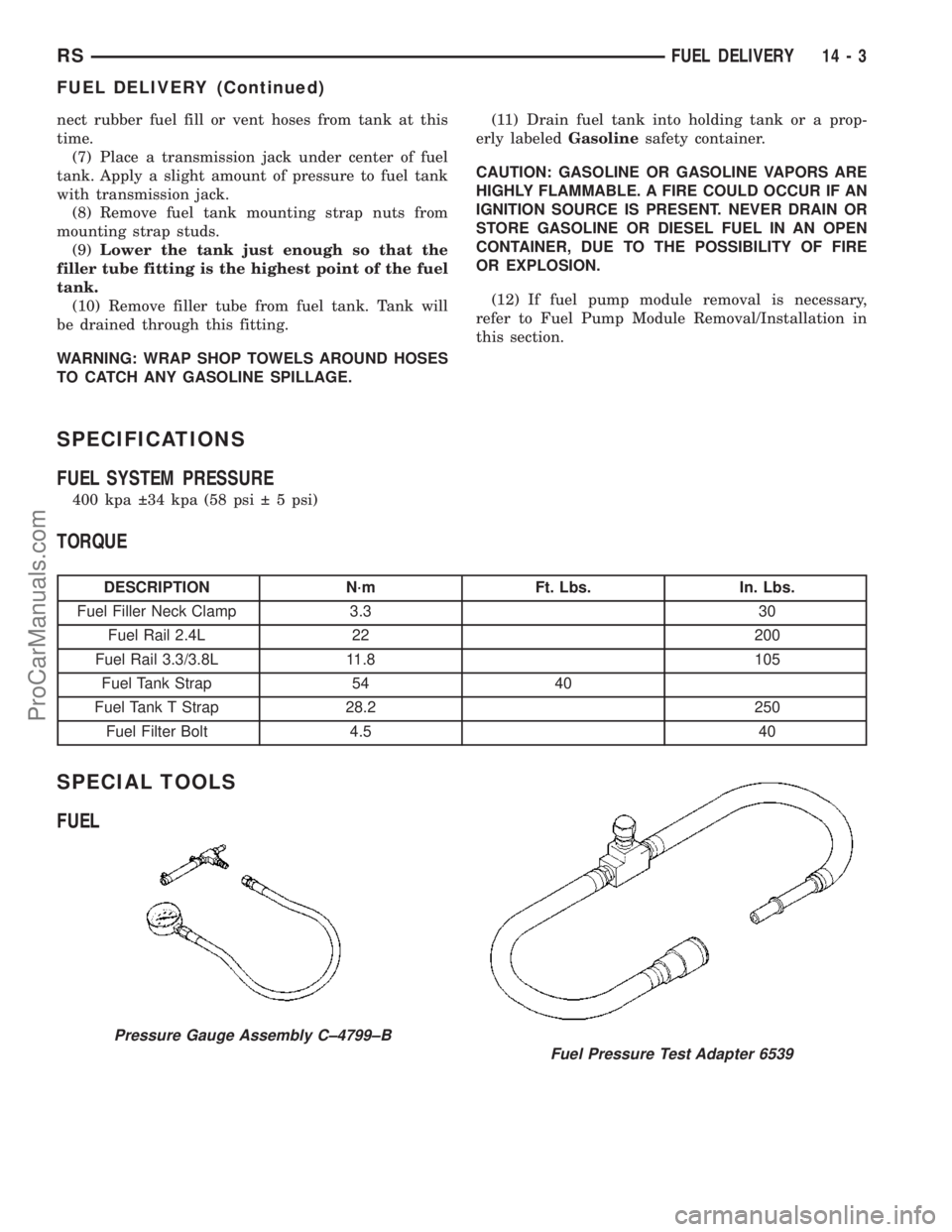
FUEL
Pressure Gauge Assembly C±4799±B
Fuel Pressure Test Adapter 6539
RSFUEL DELIVERY14-3
FUEL DELIVERY (Continued)
ProCarManuals.com
Page 1363 of 2177

FUEL FILTER
REMOVAL
(1) Release fuel pressure, refer to the Fuel release
procedure in this section.
(2) Disconnect the negative battery cable.
(3) Raise vehicle and support.
(4) Support the fuel tank with a transmission jack.
(5) Remove fuel line from the front of the tank.
(6) Remove ground strap(7) Remove the inboard side of the fuel tank straps
and front T strap fastner.
(8) Lower the tank about 6 inches (Fig. 1).
(9) Remove fuel lines from the fuel pump module.
(10) Remove fuel filter from tank.
INSTALLATION
(1) Install fuel filter to tank. Tighten bolt to 4.5
N´m (40 in. lbs.)
(2) Install fuel lines to the fuel pump module (Fig.
1).
(3) Raise tank into position.
(4) Install the fuel tank straps.Tighten bolt for
main straps to 54 N´m (40 ft. lbs.) and the T strap
bolt to 28.2 N´m (250 in. lbs.)
(5) Install the ground strap
(6) Connect the fuel line at the front of the tank.
(7) Lower vehicle.
(8) Connect the negative battery cable.
(9) Pressurize the fuel system with the DRBIIIt
and check for leaks.
FUEL LEVEL SENDING UNIT /
SENSOR
DESCRIPTION
The fuel gauge level sending unit is attached to the
side of fuel pump module. The level sensor is a vari-
able resistor.
Spanner Wrench 6856
Fuel Line Adapter 1/4
O2S (Oxygen Sensor) Remover/InstallerÐC-4907
O2S (Oxygen Sensor) Remover/Installer - 8439
Fig. 1 FUEL FILTER
14 - 4 FUEL DELIVERYRS
FUEL DELIVERY (Continued)
ProCarManuals.com
Page 1370 of 2177
REMOVAL
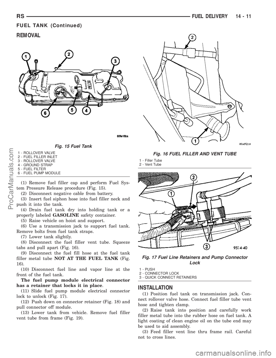
(1) Remove fuel filler cap and perform Fuel Sys-
tem Pressure Release procedure (Fig. 15).
(2) Disconnect negative cable from battery.
(3) Insert fuel siphon hose into fuel filler neck and
push it into the tank.
(4) Drain fuel tank dry into holding tank or a
properly labeledGASOLINEsafety container.
(5) Raise vehicle on hoist and support.
(6) Use a transmission jack to support fuel tank.
Remove bolts from fuel tank straps.
(7) Lower tank slightly.
(8) Disconnect the fuel filler vent tube. Squeeze
tabs and pull apart (Fig. 16).
(9) Disconnect the fuel fill hose at the fuel tank
filler metal tubeNOT AT THE FUEL TANK(Fig.
16).
(10) Disconnect fuel line and vapor line at the
front of the fuel tank.
The fuel pump module electrical connector
has a retainer that locks it in place.
(11) Slide fuel pump module electrical connector
lock to unlock (Fig. 17).
(12) Push down on connector retainer (Fig. 18) and
pull connector off module.
(13) Lower tank from vehicle. Remove fuel filler
vent tube from frame (Fig. 19).
INSTALLATION
(1) Position fuel tank on transmission jack. Con-
nect rollover valve hose. Connect fuel filler tube vent
hose and tighten clamp.
(2) Raise tank into position and carefully work
filler metal tube into the rubber hose on fuel tank. A
light coating of clean engine oil on the tube end may
be used to aid assembly.
(3) Feed filler vent line thru frame rail. Careful
not to cross lines.
Fig. 15 Fuel Tank
1 - ROLLOVER VALVE
2 - FUEL FILLER INLET
3 - ROLLOVER VALVE
4 - GROUND STRAP
5 - FUEL FILTER
6 - FUEL PUMP MODULEFig. 16 FUEL FILLER AND VENT TUBE
1 - Filler Tube
2 - Vent Tube
Fig. 17 Fuel Line Retainers and Pump Connector
Lock
1 - PUSH
2 - CONNECTOR LOCK
3 - QUICK CONNECT RETAINERS
RSFUEL DELIVERY14-11
FUEL TANK (Continued)
ProCarManuals.com
Page 1371 of 2177
(4) Tighten strap bolts to 54 N´m (40 ft. lbs.)
torque. Tighten T strap bolt to 28.2 N´m (250 in.
lbs.). Remove transmission jack.
(5) Tighten filler hose clamp to 3.3 N´m (30 in.
lbs.).
CAUTION: Ensure straps are not twisted or bent
before or after tightening strap nuts.
(6) Connect fuel pump/module electrical connector.
Place retainer in locked position.
(7) Lubricate the fuel supply line with clean 30
weight engine oil, install the quick connect fuel fit-ting. Refer to Tube/Fitting Assembly in the Fuel
Delivery section of this section.
(8) Connect the control vapor line at rear of tank.
(9) Attach filler vent line to filler tube. Pull on
connector to make sure of connection.
(10) Fill fuel tank, replace cap, and connect bat-
tery negative cable.
(11) Use the DRBIIItscan tool to pressurize the
fuel system. Check for leaks.
FUEL TANK FILLER TUBE
REMOVAL
(1) Disconnect the negative battery cable.
(2) Remove the 3 screws at the filler door.
(3) Raise and support vehicle
(4) Remove the left rear tire.
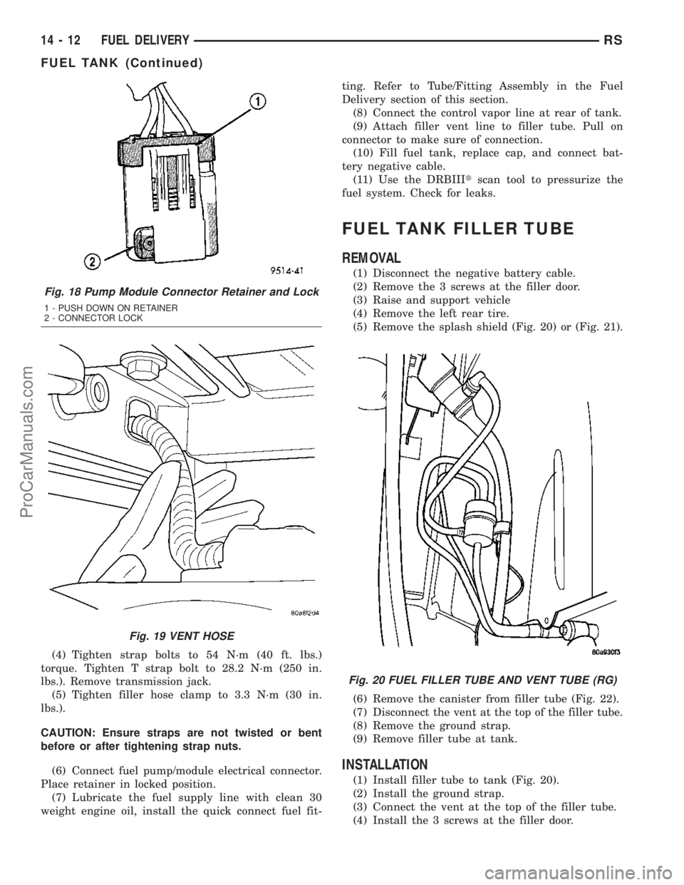
(5) Remove the splash shield (Fig. 20) or (Fig. 21).
(6) Remove the canister from filler tube (Fig. 22).
(7) Disconnect the vent at the top of the filler tube.
(8) Remove the ground strap.
(9) Remove filler tube at tank.
INSTALLATION
(1) Install filler tube to tank (Fig. 20).
(2) Install the ground strap.
(3) Connect the vent at the top of the filler tube.
(4) Install the 3 screws at the filler door.
Fig. 18 Pump Module Connector Retainer and Lock
1 - PUSH DOWN ON RETAINER
2 - CONNECTOR LOCK
Fig. 19 VENT HOSE
Fig. 20 FUEL FILLER TUBE AND VENT TUBE (RG)
14 - 12 FUEL DELIVERYRS
FUEL TANK (Continued)
ProCarManuals.com
Page 1381 of 2177
²Instrument Panel
²Body Control Module
²Air Bag System Diagnostic Module
²Full ATC Display Head (if equipped)
²ABS Module
²Transmission Control Module
²Powertrain Control Module
²Travel Module
²SKIM
SYSTEM DIAGNOSIS
OPERATION
The PCM can test many of its own input and out-
put circuits. If the PCM senses a fault in a majorsystem, the PCM stores a Diagnostic Trouble Code
(DTC) in memory.
For DTC information see On-Board Diagnostics
(Refer to 8 - ELECTRICAL/ELECTRONIC CON-
TROL MODULES/POWERTRAIN CONTROL MOD-
ULE - DESCRIPTION) .
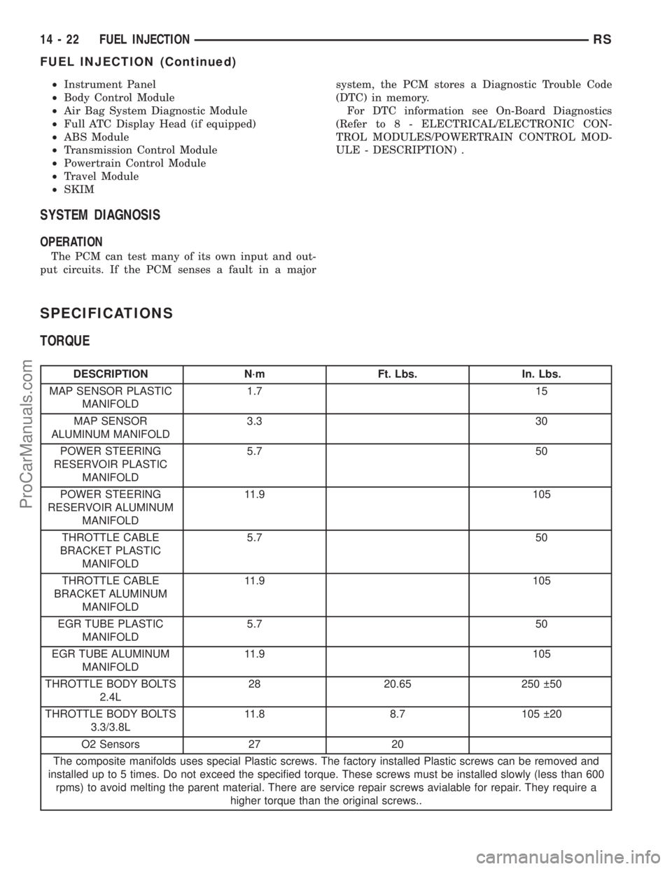
SPECIFICATIONS
TORQUE
DESCRIPTION N´m Ft. Lbs. In. Lbs.
MAP SENSOR PLASTIC
MANIFOLD1.7 15
MAP SENSOR
ALUMINUM MANIFOLD3.3 30
POWER STEERING
RESERVOIR PLASTIC
MANIFOLD5.7 50
POWER STEERING
RESERVOIR ALUMINUM
MANIFOLD11.9 105
THROTTLE CABLE
BRACKET PLASTIC
MANIFOLD5.7 50
THROTTLE CABLE
BRACKET ALUMINUM
MANIFOLD11.9 105
EGR TUBE PLASTIC
MANIFOLD5.7 50
EGR TUBE ALUMINUM
MANIFOLD11.9 105
THROTTLE BODY BOLTS
2.4L28 20.65 250 50
THROTTLE BODY BOLTS
3.3/3.8L11.8 8.7 105 20
O2 Sensors 27 20
The composite manifolds uses special Plastic screws. The factory installed Plastic screws can be removed and
installed up to 5 times. Do not exceed the specified torque. These screws must be installed slowly (less than 600
rpms) to avoid melting the parent material. There are service repair screws avialable for repair. They require a
higher torque than the original screws..
14 - 22 FUEL INJECTIONRS
FUEL INJECTION (Continued)
ProCarManuals.com
Page 1383 of 2177
INSTALLATION
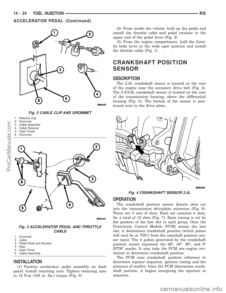
(1) Position accelerator pedal assembly on dash
panel. Install retaining nuts. Tighten retaining nuts
to 12 N´m (105 in. lbs.) torque (Fig. 3).(2) From inside the vehicle, hold up the pedal and
install the throttle cable and pedal retainer in the
upper end of the pedal lever (Fig. 2).
(3) From the engine compartment, hold the throt-
tle body lever in the wide open position and install
the throttle cable (Fig. 1).
CRANKSHAFT POSITION
SENSOR
DESCRIPTION
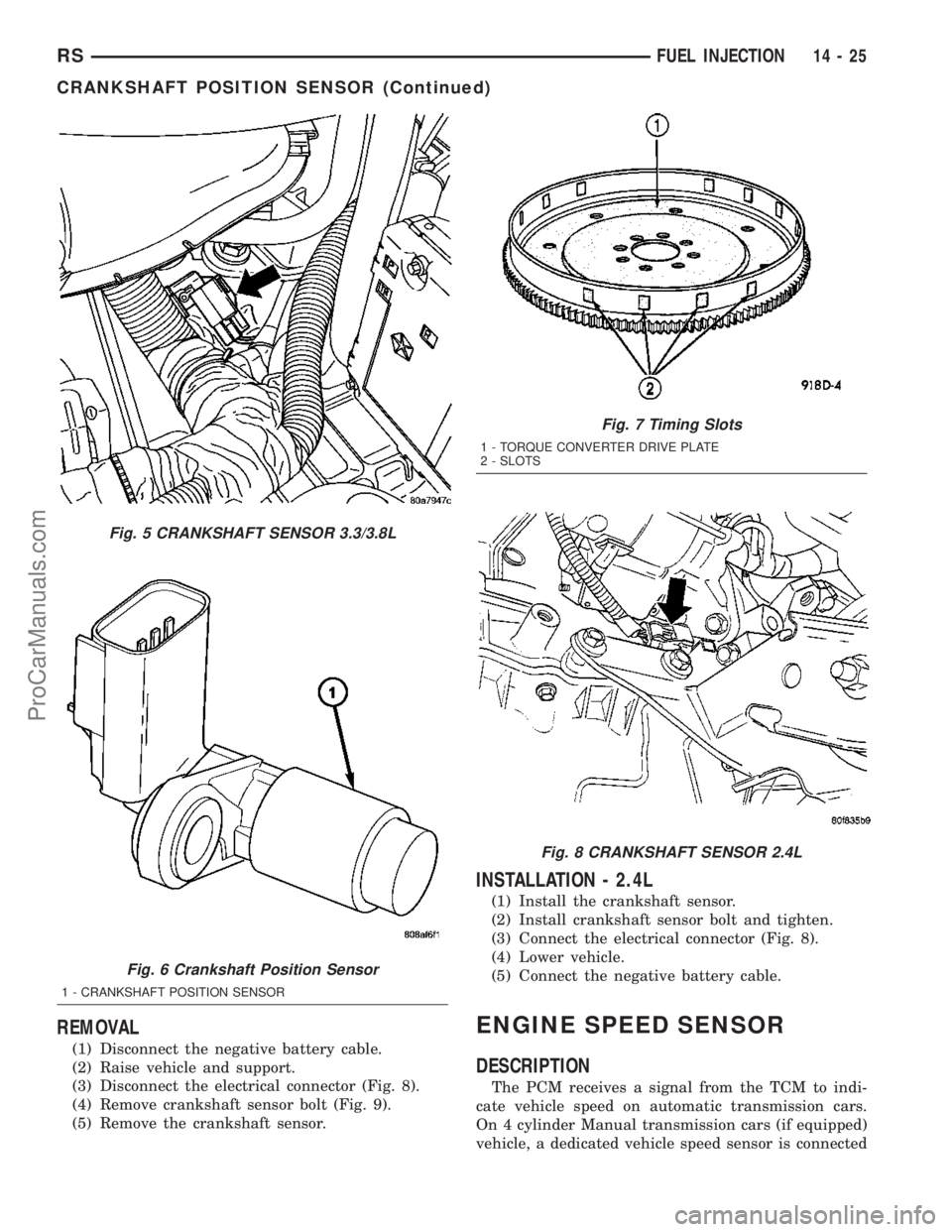
The 2.4L crankshaft sensor is located on the rear
of the engine near the accessory drive belt (Fig. 4).
The 3.3/3.8L crankshaft sensor is located on the rear
of the transmission housing, above the differential
housing (Fig. 5). The bottom of the sensor is posi-
tioned next to the drive plate.
OPERATION
The crankshaft position sensor detects slots cut
into the transmission driveplate extension (Fig. 6).
There are 3 sets of slots. Each set contains 4 slots,
for a total of 12 slots (Fig. 7). Basic timing is set by
the position of the last slot in each group. Once the
Powertrain Control Module (PCM) senses the last
slot, it determines crankshaft position (which piston
will next be at TDC) from the camshaft position sen-
sor input. The 4 pulses generated by the crankshaft
position sensor represent the 69É, 49É, 29É, and 9É
BTDC marks. It may take the PCM one engine rev-
olution to determine crankshaft position.
The PCM uses crankshaft position reference to
determine injector sequence, ignition timing and the
presence of misfire. Once the PCM determines crank-
shaft position, it begins energizing the injectors in
sequence.
Fig. 2 CABLE CLIP AND GROMMET
1 - Retainer Clip
2 - Grommet
3 - Cable Assembly
4 - Cable Retainer
5 - Dash Panel
6 - Grommet
Fig. 3 ACCELERATOR PEDAL AND THROTTLE
CABLE
1 - Grommet
2 - Cable
3 - Pedal Shaft and Bracket
4 - Seal
5 - Dash Panel
6 - Cable Assembly
Fig. 4 CRANKSHAFT SENSOR 2.4L
14 - 24 FUEL INJECTIONRS
ACCELERATOR PEDAL (Continued)
ProCarManuals.com
Page 1384 of 2177
REMOVAL
(1) Disconnect the negative battery cable.
(2) Raise vehicle and support.
(3) Disconnect the electrical connector (Fig. 8).
(4) Remove crankshaft sensor bolt (Fig. 9).
(5) Remove the crankshaft sensor.
INSTALLATION - 2.4L
(1) Install the crankshaft sensor.
(2) Install crankshaft sensor bolt and tighten.
(3) Connect the electrical connector (Fig. 8).
(4) Lower vehicle.
(5) Connect the negative battery cable.
ENGINE SPEED SENSOR
DESCRIPTION
The PCM receives a signal from the TCM to indi-
cate vehicle speed on automatic transmission cars.
On 4 cylinder Manual transmission cars (if equipped)
vehicle, a dedicated vehicle speed sensor is connected
Fig. 5 CRANKSHAFT SENSOR 3.3/3.8L
Fig. 6 Crankshaft Position Sensor
1 - CRANKSHAFT POSITION SENSOR
Fig. 7 Timing Slots
1 - TORQUE CONVERTER DRIVE PLATE
2 - SLOTS
Fig. 8 CRANKSHAFT SENSOR 2.4L
RSFUEL INJECTION14-25
CRANKSHAFT POSITION SENSOR (Continued)
ProCarManuals.com
Page 1385 of 2177
to the PCM.On V-6 Manual transmission cars (if
equipped) vehicle, the ABS module provides the sig-
nal to the PCM for vehicle speed.
OPERATION
The Transmission Control Module (TCM) supplies
the road speed and distance traveled inputs to the
PCM. From these inputs and the throttle position
sensor input, the PCM determines when a decelera-
tion condition occurs.
FUEL INJECTOR
DESCRIPTION
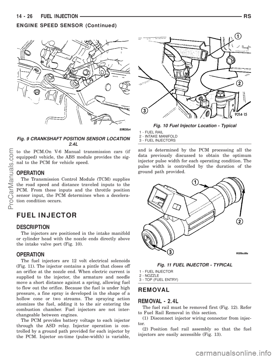
The injectors are positioned in the intake manifold
or cylinder head with the nozzle ends directly above
the intake valve port (Fig. 10).
OPERATION
The fuel injectors are 12 volt electrical solenoids
(Fig. 11). The injector contains a pintle that closes off
an orifice at the nozzle end. When electric current is
supplied to the injector, the armature and needle
move a short distance against a spring, allowing fuel
to flow out the orifice. Because the fuel is under high
pressure, a fine spray is developed in the shape of a
hollow cone or two streams. The spraying action
atomizes the fuel, adding it to the air entering the
combustion chamber. Fuel injectors are not inter-
changeable between engines.
The PCM provides battery voltage to each injector
through the ASD relay. Injector operation is con-
trolled by a ground path provided for each injector by
the PCM. Injector on-time (pulse-width) is variable,and is determined by the PCM processing all the
data previously discussed to obtain the optimum
injector pulse width for each operating condition. The
pulse width is controlled by the duration of the
ground path provided.
REMOVAL
REMOVAL - 2.4L
The fuel rail must be removed first (Fig. 12). Refer
to Fuel Rail Removal in this section.
(1) Disconnect injector wiring connector from injec-
tor.
(2) Position fuel rail assembly so that the fuel
injectors are easily accessible (Fig. 13).
Fig. 9 CRANKSHAFT POSITION SENSOR LOCATION
2.4L
Fig. 10 Fuel Injector Location - Typical
1 - FUEL RAIL
2 - INTAKE MANIFOLD
3 - FUEL INJECTORS
Fig. 11 FUEL INJECTOR - TYPICAL
1 - FUEL INJECTOR
2 - NOZZLE
3 - TOP (FUEL ENTRY)
14 - 26 FUEL INJECTIONRS
ENGINE SPEED SENSOR (Continued)
ProCarManuals.com