2003 CHRYSLER CARAVAN check oil
[x] Cancel search: check oilPage 2002 of 2177
diagnose the A/C system control and distribution sys-
tems. Refer to the appropriate diagnostic informa-
tion.
MANUAL TEMPERATURE CONTROL
The front blower speed and rear blower speed (if
equipped with rear HVAC) must be set to High and
the evaporator temperature sensor must be greater
than 55É F or the test will fail immediately. The test
is activated by depressing the A/C and PWR buttons
simultaneously and holding them depressed for no
less than five seconds. The PWR and A/C LEDs will
blink on and off until the test is complete. If the
LEDs stop blinking before two minutes, then the cool
down test has been completed successfully. If the two
minutes expire without the expansion valve temper-
ature reaching 20É F less than the outside air tem-
perature, then the cool down test has been failed and
further A/C system diagnosis is required. If the test
is failed, the LEDs will continue to blink until the
vehicle has been driven for greater than (8 miles).
AUTOMATIC TEMPERATURE CONTROL
The ambient air temperature in the room where
the vehicle will be tested must be a minimum of 21É
C (70ÉF) for this test. The test is activated by
depressing the A/C and PWR buttons simultaneously
and holding them depressed for no less than four sec-
onds. The snowflake icon and the DELAY text in the
ATC display will blink on and off alternately until
the test is complete. If the snowflake icon and the
DELAY text stop blinking before two minutes, then
the cool down test has been completed successfully. If
the two minutes expire without the evaporator tem-
perature reaching 20É F less than the evaporator ini-
tial temperature, then the cool down test has been
failed and further A/C system diagnosis is required.
If the test is failed, the snowflake icon and the
DELAY text will continue to blink across ignition
cycles until the vehicle has been driven for greater
than (8 miles).
DIAGNOSIS AND TESTING - A/C
PERFORMANCE TEST
An air conditioning performance test is the best
way to determine whether the system is performing
up to standard. This test also provides valuable clues
as to the possible cause of trouble with the air con-
ditioning system. The ambient air temperature in the
location where the vehicle will be tested must be a
minimum of 21É C (70ÉF) for this test.
WARNING: REFER TO THE APPLICABLE WARN-
INGS AND CAUTIONS FOR THIS SYSTEM BEFOREPERFORMING THE FOLLOWING OPERATION.
(Refer to 24 - HEATING & AIR CONDITIONING/
PLUMBING - FRONT - WARNING - A/C PLUMBING)
and (Refer to 24 - HEATING & AIR CONDITIONING/
PLUMBING - FRONT - CAUTION - A/C PLUMBING).
NOTE: When connecting the service equipment
coupling to the line fitting, verify that the valve of
the coupling is fully closed. This will reduce the
amount of effort required to make the connection.
(1) Connect a tachometer to monitor the engine
speed.
(2) Remove the caps from the refrigerant system
service ports and attach a manifold gauge set to
monitor the refrigerant system pressures.
(3) Set the heater-air conditioner controls so that
the compressor is engaged, the air within the vehicle
is being recirculated, the output air is directed
through the panel outlets, the temperature control is
in the full cool position, and the blower motor is oper-
ating at its highest speed.
(4) Start the engine and allow the engine to oper-
ate for about five minutes or until it reaches normal
operating temperature. Then hold the engine speed
at 1000 rpm with the compressor clutch engaged. If
the compressor clutch does not engage, proceed with
diagnosis of the compressor clutch coil. (Refer to 24 -
HEATING & AIR CONDITIONING/CONTROLS -
FRONT/COMPRESSOR CLUTCH COIL - DIAGNO-
SIS AND TESTING).
(5) Close all the vehicle windows and doors.
(6) Insert a thermometer in the left center panel
outlet and operate the engine for five minutes.
(7) With the compressor clutch engaged, record the
left center panel outlet discharge air temperature,
the discharge pressure (high side service port), and
the suction pressure (low side service port). The com-
pressor clutch may cycle, depending upon the ambi-
ent temperature and humidity. If the clutch cycles,
use the readings obtained before the clutch disen-
gaged.
(8) Compare the discharge air temperature read-
ing to the Performance Temperature and Pressure
chart. If the temperature reading is high, check the
refrigerant system for leaks and proper refrigerant
charge level. (Refer to 24 - HEATING & AIR CONDI-
TIONING/PLUMBING - FRONT/REFRIGERANT -
DIAGNOSIS AND TESTING - REFRIGERANT SYS-
TEM LEAKS) and (Refer to 24 - HEATING & AIR
CONDITIONING/PLUMBING - FRONT/REFRIGER-
ANT - DIAGNOSIS AND TESTING - REFRIGER-
ANT SYSTEM CHARGE LEVEL).
RSHEATING & AIR CONDITIONING24-5
HEATING & AIR CONDITIONING (Continued)
ProCarManuals.com
Page 2012 of 2177
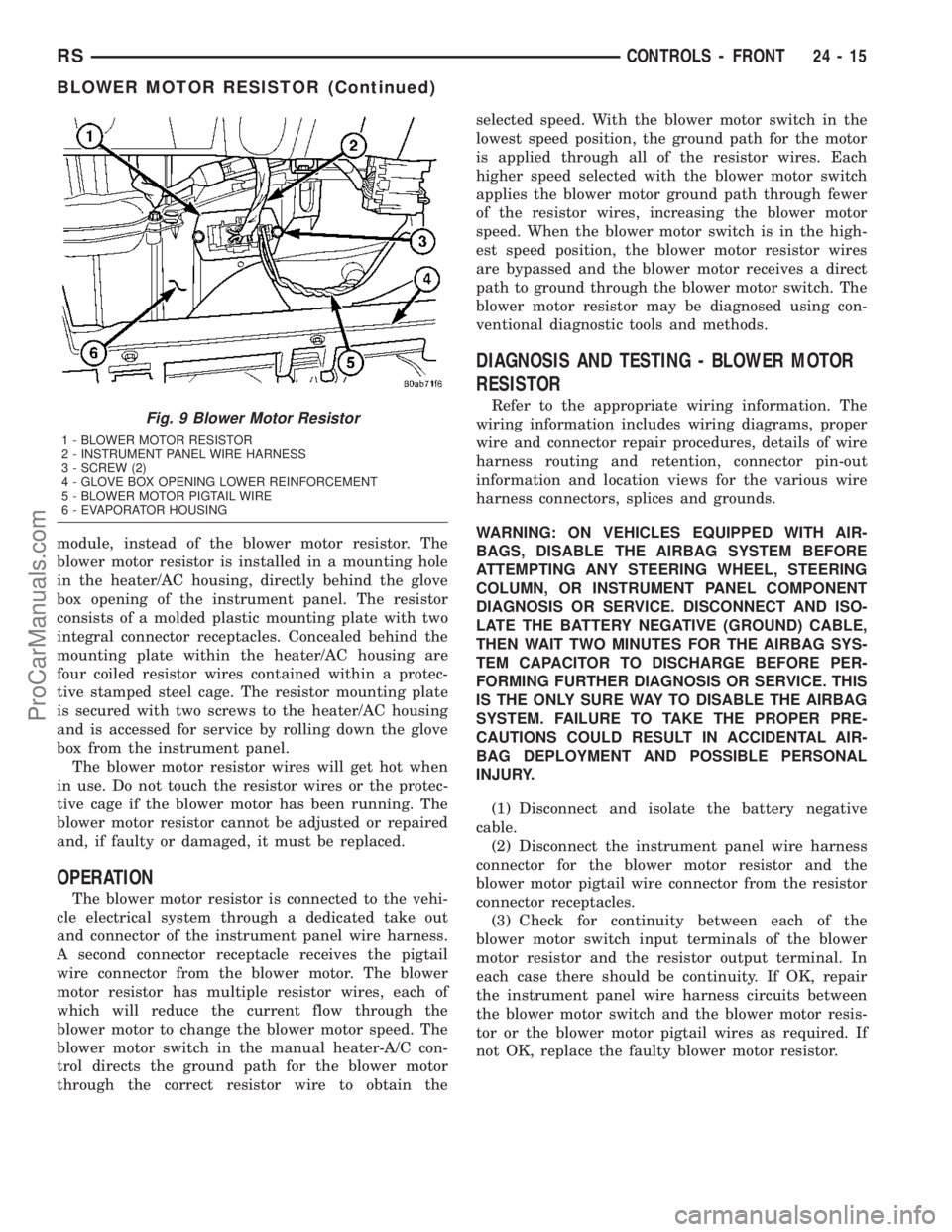
module, instead of the blower motor resistor. The
blower motor resistor is installed in a mounting hole
in the heater/AC housing, directly behind the glove
box opening of the instrument panel. The resistor
consists of a molded plastic mounting plate with two
integral connector receptacles. Concealed behind the
mounting plate within the heater/AC housing are
four coiled resistor wires contained within a protec-
tive stamped steel cage. The resistor mounting plate
is secured with two screws to the heater/AC housing
and is accessed for service by rolling down the glove
box from the instrument panel.
The blower motor resistor wires will get hot when
in use. Do not touch the resistor wires or the protec-
tive cage if the blower motor has been running. The
blower motor resistor cannot be adjusted or repaired
and, if faulty or damaged, it must be replaced.
OPERATION
The blower motor resistor is connected to the vehi-
cle electrical system through a dedicated take out
and connector of the instrument panel wire harness.
A second connector receptacle receives the pigtail
wire connector from the blower motor. The blower
motor resistor has multiple resistor wires, each of
which will reduce the current flow through the
blower motor to change the blower motor speed. The
blower motor switch in the manual heater-A/C con-
trol directs the ground path for the blower motor
through the correct resistor wire to obtain theselected speed. With the blower motor switch in the
lowest speed position, the ground path for the motor
is applied through all of the resistor wires. Each
higher speed selected with the blower motor switch
applies the blower motor ground path through fewer
of the resistor wires, increasing the blower motor
speed. When the blower motor switch is in the high-
est speed position, the blower motor resistor wires
are bypassed and the blower motor receives a direct
path to ground through the blower motor switch. The
blower motor resistor may be diagnosed using con-
ventional diagnostic tools and methods.
DIAGNOSIS AND TESTING - BLOWER MOTOR
RESISTOR
Refer to the appropriate wiring information. The
wiring information includes wiring diagrams, proper
wire and connector repair procedures, details of wire
harness routing and retention, connector pin-out
information and location views for the various wire
harness connectors, splices and grounds.
WARNING: ON VEHICLES EQUIPPED WITH AIR-
BAGS, DISABLE THE AIRBAG SYSTEM BEFORE
ATTEMPTING ANY STEERING WHEEL, STEERING
COLUMN, OR INSTRUMENT PANEL COMPONENT
DIAGNOSIS OR SERVICE. DISCONNECT AND ISO-
LATE THE BATTERY NEGATIVE (GROUND) CABLE,
THEN WAIT TWO MINUTES FOR THE AIRBAG SYS-
TEM CAPACITOR TO DISCHARGE BEFORE PER-
FORMING FURTHER DIAGNOSIS OR SERVICE. THIS
IS THE ONLY SURE WAY TO DISABLE THE AIRBAG
SYSTEM. FAILURE TO TAKE THE PROPER PRE-
CAUTIONS COULD RESULT IN ACCIDENTAL AIR-
BAG DEPLOYMENT AND POSSIBLE PERSONAL
INJURY.
(1) Disconnect and isolate the battery negative
cable.
(2) Disconnect the instrument panel wire harness
connector for the blower motor resistor and the
blower motor pigtail wire connector from the resistor
connector receptacles.
(3) Check for continuity between each of the
blower motor switch input terminals of the blower
motor resistor and the resistor output terminal. In
each case there should be continuity. If OK, repair
the instrument panel wire harness circuits between
the blower motor switch and the blower motor resis-
tor or the blower motor pigtail wires as required. If
not OK, replace the faulty blower motor resistor.Fig. 9 Blower Motor Resistor
1 - BLOWER MOTOR RESISTOR
2 - INSTRUMENT PANEL WIRE HARNESS
3 - SCREW (2)
4 - GLOVE BOX OPENING LOWER REINFORCEMENT
5 - BLOWER MOTOR PIGTAIL WIRE
6 - EVAPORATOR HOUSING
RSCONTROLS - FRONT24-15
BLOWER MOTOR RESISTOR (Continued)
ProCarManuals.com
Page 2014 of 2177
damaged, the clutch electromagnetic coil unit must
be replaced.
OPERATION
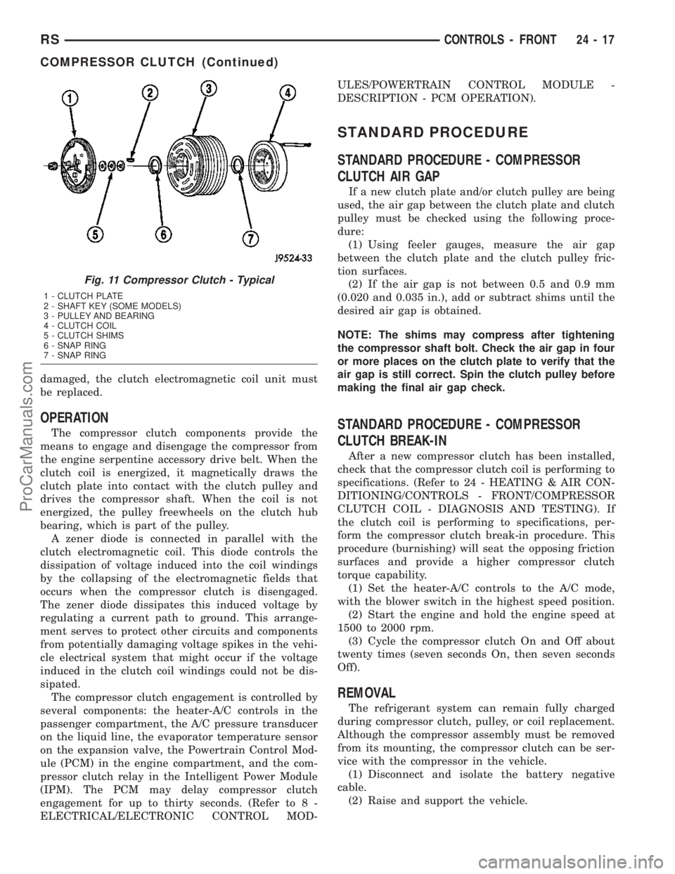
The compressor clutch components provide the
means to engage and disengage the compressor from
the engine serpentine accessory drive belt. When the
clutch coil is energized, it magnetically draws the
clutch plate into contact with the clutch pulley and
drives the compressor shaft. When the coil is not
energized, the pulley freewheels on the clutch hub
bearing, which is part of the pulley.
A zener diode is connected in parallel with the
clutch electromagnetic coil. This diode controls the
dissipation of voltage induced into the coil windings
by the collapsing of the electromagnetic fields that
occurs when the compressor clutch is disengaged.
The zener diode dissipates this induced voltage by
regulating a current path to ground. This arrange-
ment serves to protect other circuits and components
from potentially damaging voltage spikes in the vehi-
cle electrical system that might occur if the voltage
induced in the clutch coil windings could not be dis-
sipated.
The compressor clutch engagement is controlled by
several components: the heater-A/C controls in the
passenger compartment, the A/C pressure transducer
on the liquid line, the evaporator temperature sensor
on the expansion valve, the Powertrain Control Mod-
ule (PCM) in the engine compartment, and the com-
pressor clutch relay in the Intelligent Power Module
(IPM). The PCM may delay compressor clutch
engagement for up to thirty seconds. (Refer to 8 -
ELECTRICAL/ELECTRONIC CONTROL MOD-ULES/POWERTRAIN CONTROL MODULE -
DESCRIPTION - PCM OPERATION).
STANDARD PROCEDURE
STANDARD PROCEDURE - COMPRESSOR
CLUTCH AIR GAP
If a new clutch plate and/or clutch pulley are being
used, the air gap between the clutch plate and clutch
pulley must be checked using the following proce-
dure:
(1) Using feeler gauges, measure the air gap
between the clutch plate and the clutch pulley fric-
tion surfaces.
(2) If the air gap is not between 0.5 and 0.9 mm
(0.020 and 0.035 in.), add or subtract shims until the
desired air gap is obtained.
NOTE: The shims may compress after tightening
the compressor shaft bolt. Check the air gap in four
or more places on the clutch plate to verify that the
air gap is still correct. Spin the clutch pulley before
making the final air gap check.
STANDARD PROCEDURE - COMPRESSOR
CLUTCH BREAK-IN
After a new compressor clutch has been installed,
check that the compressor clutch coil is performing to
specifications. (Refer to 24 - HEATING & AIR CON-
DITIONING/CONTROLS - FRONT/COMPRESSOR
CLUTCH COIL - DIAGNOSIS AND TESTING). If
the clutch coil is performing to specifications, per-
form the compressor clutch break-in procedure. This
procedure (burnishing) will seat the opposing friction
surfaces and provide a higher compressor clutch
torque capability.
(1) Set the heater-A/C controls to the A/C mode,
with the blower switch in the highest speed position.
(2) Start the engine and hold the engine speed at
1500 to 2000 rpm.
(3) Cycle the compressor clutch On and Off about
twenty times (seven seconds On, then seven seconds
Off).
REMOVAL
The refrigerant system can remain fully charged
during compressor clutch, pulley, or coil replacement.
Although the compressor assembly must be removed
from its mounting, the compressor clutch can be ser-
vice with the compressor in the vehicle.
(1) Disconnect and isolate the battery negative
cable.
(2) Raise and support the vehicle.
Fig. 11 Compressor Clutch - Typical
1 - CLUTCH PLATE
2 - SHAFT KEY (SOME MODELS)
3 - PULLEY AND BEARING
4 - CLUTCH COIL
5 - CLUTCH SHIMS
6 - SNAP RING
7 - SNAP RING
RSCONTROLS - FRONT24-17
COMPRESSOR CLUTCH (Continued)
ProCarManuals.com
Page 2016 of 2177
(2) Examine the friction surfaces of the clutch pul-
ley and the clutch plate for oil contamination. If the
friction surfaces are oily, the clutch pulley and clutch
plate should be replaced. Also inspect the shaft andnose area of the compressor for oil. Remove the felt
packing from around the compressor shaft in the
compressor front cover. If the felt is saturated with
oil, the compressor front shaft seal is leaking and the
compressor will also have to be replaced.
(3) Check the clutch pulley bearing for roughness
or excessive leakage of grease. Replace the clutch
pulley and clutch plate if the bearing is faulty.
INSTALLATION
The refrigerant system can remain fully charged
during compressor clutch, pulley, or coil replacement.
Although the compressor assembly must be removed
from its mounting, the compressor clutch can be ser-
vice with the compressor in the vehicle.
(1) Align the dowel pin on the back of the clutch
coil with the hole in the compressor front cover, and
position the clutch coil onto the compressor. Be cer-
tain that the clutch coil pigtail wires are properly ori-
ented and routed so that they are not pinched
between the compressor front cover and the clutch
coil.
NOTE: A new snap ring must be used to secure the
clutch coil to the compressor. The bevel side of the
snap ring must face outward.
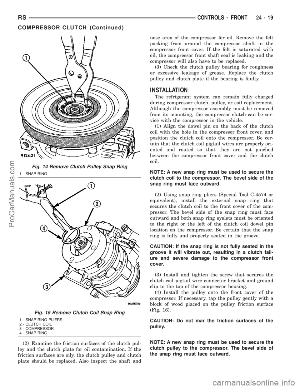
(2) Using snap ring pliers (Special Tool C-4574 or
equivalent), install the external snap ring that
secures the clutch coil to the front cover of the com-
pressor. The bevel side of the snap ring must face
outward and both snap ring eyelets must be oriented
to the right or the left of the clutch coil dowel pin
location on the compressor. Be certain that the snap
ring is fully and properly seated in the groove.
CAUTION: If the snap ring is not fully seated in the
groove it will vibrate out, resulting in a clutch fail-
ure and severe damage to the compressor front
cover.
(3) Install and tighten the screw that secures the
clutch coil pigtail wire connector bracket and ground
clip to the top of the compressor housing.
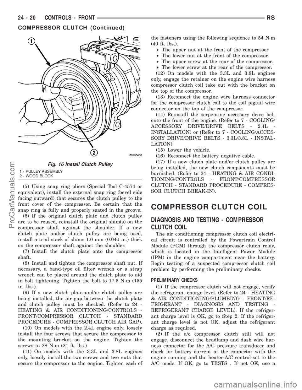
(4) Install the pulley onto the front cover of the
compressor. If necessary, tap the pulley gently with a
block of wood placed on the pulley friction surface
(Fig. 16).
CAUTION: Do not mar the friction surfaces of the
pulley.
NOTE: A new snap ring must be used to secure the
clutch pulley to the compressor. The bevel side of
the snap ring must face outward.
Fig. 14 Remove Clutch Pulley Snap Ring
1 - SNAP RING
Fig. 15 Remove Clutch Coil Snap Ring
1 - SNAP RING PLIERS
2 - CLUTCH COIL
3 - COMPRESSOR
4 - SNAP RING
RSCONTROLS - FRONT24-19
COMPRESSOR CLUTCH (Continued)
ProCarManuals.com
Page 2017 of 2177
(5) Using snap ring pliers (Special Tool C-4574 or
equivalent), install the external snap ring (bevel side
facing outward) that secures the clutch pulley to the
front cover of the compressor. Be certain that the
snap ring is fully and properly seated in the groove.
(6) If the original clutch plate and clutch pulley
are to be reused, reinstall the original shim(s) on the
compressor shaft against the shoulder. If a new
clutch plate and/or clutch pulley are being used,
install a trial stack of shims 1.0 mm (0.040 in.) thick
on the compressor shaft against the shoulder.
(7) Install the clutch plate onto the compressor
shaft.
(8) Install and tighten the compressor shaft nut. If
necessary, a band-type oil filter wrench or a strap
wrench can be placed around the clutch plate to aid
in bolt tightening. Tighten the bolt to 17.5 N´m (155
in. lbs.).
(9) If a new clutch plate and/or clutch pulley are
being installed, the air gap between the clutch plate
and clutch pulley must be checked. (Refer to 24 -
HEATING & AIR CONDITIONING/CONTROLS -
FRONT/COMPRESSOR CLUTCH - STANDARD
PROCEDURE - COMPRESSOR CLUTCH AIR GAP).
(10) On models with the 2.4L engine only, loosely
install the four screws that secure the compressor to
the mounting bracket on the engine. Tighten the
screws to 28 N´m (21 ft. lbs.).
(11) On models with the 3.3L and 3.8L engines
only, loosely install the two screws and two nuts that
secure the compressor to the engine. Tighten each ofthe fasteners using the following sequence to 54 N´m
(40 ft. lbs.).
²The upper nut at the front of the compressor.
²The lower nut at the front of the compressor.
²The upper screw at the rear of the compressor.
²The lower screw at the rear of the compressor.
(12) On models with the 3.3L and 3.8L engines
only, engage the retainer on the engine wire harness
compressor clutch coil take out with the bracket on
the top of the compressor.
(13) Reconnect the engine wire harness connector
for the compressor clutch coil to the coil pigtail wire
connector on the top of the compressor.
(14) Reinstall the serpentine accessory drive belt
onto the front of the engine. (Refer to 7 - COOLING/
ACCESSORY DRIVE/DRIVE BELTS - 2.4L -
INSTALLATION) or (Refer to 7 - COOLING/ACCES-
SORY DRIVE/DRIVE BELTS - 3.3L/3.8L - INSTAL-
LATION).
(15) Lower the vehicle.
(16) Reconnect the battery negative cable.
(17) If a new clutch plate and/or clutch pulley are
being installed, the new clutch components must be
burnished. (Refer to 24 - HEATING & AIR CONDI-
TIONING/CONTROLS - FRONT/COMPRESSOR
CLUTCH - STANDARD PROCEDURE - COMPRES-
SOR CLUTCH BREAK-IN).
COMPRESSOR CLUTCH COIL
DIAGNOSIS AND TESTING - COMPRESSOR
CLUTCH COIL
The air conditioning compressor clutch coil electri-
cal circuit is controlled by the Powertrain Control
Module (PCM) through the compressor clutch relay,
which is located in the Intelligent Power Module
(IPM) in the engine compartment near the battery.
Begin testing of a suspected compressor clutch coil
problem by performing the preliminary checks.
PRELIMINARY CHECKS
(1) If the compressor clutch will not engage, verify
the refrigerant charge level. (Refer to 24 - HEATING
& AIR CONDITIONING/PLUMBING - FRONT/RE-
FRIGERANT - DIAGNOSIS AND TESTING -
REFRIGERANT CHARGE LEVEL). If the refriger-
ant charge level is OK, go to Step 2. If the refriger-
ant charge level is not OK, adjust the refrigerant
charge as required.
(2) If the a/c compressor clutch still will not
engage, disconnect the headlamp and dash wire har-
ness connector for the A/C pressure transducer and
check for battery current at the connector with the
engine running and the heater-A/C control set to the
A/C mode. If OK, go to TESTS . If not OK, use a
Fig. 16 Install Clutch Pulley
1 - PULLEY ASSEMBLY
2 - WOOD BLOCK
24 - 20 CONTROLS - FRONTRS
COMPRESSOR CLUTCH (Continued)
ProCarManuals.com
Page 2062 of 2177
NOTE: If a replacement compressor is being
installed, be certain to drain and measure the refrig-
erant oil contained in the removed compressor.
This will determine how much oil the replacement
compressor must contain before it is installed.
(Refer to 24 - HEATING & AIR CONDITIONING/
PLUMBING - FRONT/REFRIGERANT OIL - STAN-
DARD PROCEDURE - REFRIGERANT OIL LEVEL).
NOTE: The filter drier should always be replaced
when the compressor is replaced. This will remove
any contaminants including moisture from the sys-
tem.
REMOVAL - COMPRESSOR MOUNTING
BRACKET - 2.4L ENGINE
(1) Remove the compressor from the mounting
bracket. (Refer to 24 - HEATING & AIR CONDI-
TIONING/PLUMBING/COMPRESSOR - REMOVAL).
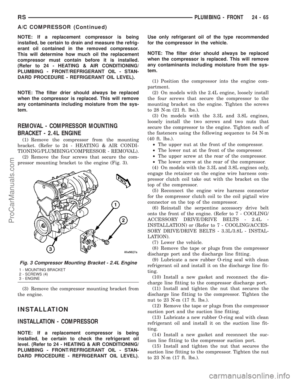
(2) Remove the four screws that secure the com-
pressor mounting bracket to the engine (Fig. 3).
(3) Remove the compressor mounting bracket from
the engine.
INSTALLATION
INSTALLATION - COMPRESSOR
NOTE: If a replacement compressor is being
installed, be certain to check the refrigerant oil
level. (Refer to 24 - HEATING & AIR CONDITIONING/
PLUMBING - FRONT/REFRIGERANT OIL - STAN-
DARD PROCEDURE - REFRIGERANT OIL LEVEL).Use only refrigerant oil of the type recommended
for the compressor in the vehicle.
NOTE: The filter drier should always be replaced
when the compressor is replaced. This will remove
any contaminants including moisture from the sys-
tem.
(1) Position the compressor into the engine com-
partment.
(2) On models with the 2.4L engine, loosely install
the four screws that secure the compressor to the
mounting bracket on the engine. Tighten the screws
to 28 N´m (21 ft. lbs.).
(3) On models with the 3.3L and 3.8L engines,
loosely install the two screws and two nuts that
secure the compressor to the engine. Tighten each of
the fasteners using the following sequence to 54 N´m
(40 ft. lbs.).
²The upper nut at the front of the compressor.
²The lower nut at the front of the compressor.
²The upper screw at the rear of the compressor.
²The lower screw at the rear of the compressor.
(4) On models with the 3.3L and 3.8L engines only,
engage the retainer on the engine wire harness com-
pressor clutch coil take out with the bracket on the
top of the compressor.
(5) Reconnect the engine wire harness connector
for the compressor clutch coil to the coil pigtail wire
connector on the top of the compressor.
(6) Reinstall the serpentine accessory drive belt
onto the front of the engine. (Refer to 7 - COOLING/
ACCESSORY DRIVE/DRIVE BELTS - 2.4L -
INSTALLATION) or (Refer to 7 - COOLING/ACCES-
SORY DRIVE/DRIVE BELTS - 3.3L/3.8L - INSTAL-
LATION).
(7) Lower the vehicle.
(8) Remove the tape or plugs from the compressor
discharge port and the discharge line fitting.
(9) Lubricate a new rubber O-ring seal with clean
refrigerant oil and install it on the discharge line fit-
ting.
(10) Install a new gasket and reconnect the dis-
charge line fitting to the compressor discharge port.
(11) Install and tighten the nut that secures the
discharge line fitting to the compressor. Tighten the
nut to 23 N´m (17 ft. lbs.).
(12) Remove the tape or plugs from the compressor
suction port and the suction line fitting.
(13) Lubricate a new rubber O-ring seal with clean
refrigerant oil and install it on the suction line fit-
ting.
(14) Install a new gasket and reconnect the suc-
tion line fitting to the compressor suction port.
(15) Install and tighten the nut that secures the
suction line fitting to the compressor. Tighten the nut
to 23 N´m (17 ft. lbs.).
Fig. 3 Compressor Mounting Bracket - 2.4L Engine
1 - MOUNTING BRACKET
2 - SCREWS (4)
3 - ENGINE
RSPLUMBING - FRONT24-65
A/C COMPRESSOR (Continued)
ProCarManuals.com
Page 2065 of 2177
(7) Remove the tape or plugs from the condenser
outlet port and the liquid line fitting.
(8) Lubricate a new rubber O-ring seal with clean
refrigerant oil and install it on the liquid line fitting.
(9) Install a new dual plan seal and reconnect the
liquid line fitting to the condenser outlet port on the
right side of the cooling module.
(10) Install and tighten the nut that secures the
liquid line fitting to the condenser. Tighten the nut to
23 N´m (17 ft. lbs.).
(11) Remove the tape or plugs from the condenser
inlet port and the discharge line fitting.
(12) Lubricate a new rubber O-ring seal with clean
refrigerant oil and install it on the discharge line fit-
ting.
(13) Install a new dual plan seal and reconnect the
discharge line fitting to the condenser inlet port on
the right side of the cooling module.
(14) Install and tighten the nut that secures the
discharge line fitting to the condenser. Tighten the
nut to 23 N´m (17 ft. lbs.).
(15) Reconnect the hoses to the transmission oil
cooler fittings on the left side of the cooling module.
(Refer to 7 - COOLING/TRANSMISSION/TRANS
COOLER LINES - INSTALLATION).
(16) Reposition the hood latch unit to the front of
the radiator closure panel crossmember.
(17) Install and tighten the two screws that secure
the hood latch unit to the front of the radiator clo-
sure panel crossmember. Check and adjust the hood
latch as needed. Tighten the screws to 14 N´m (123
in. lbs.).
(18) Position the radiator sight shield onto the
radiator closure panel crossmember.
(19) Install and tighten the five small screws that
secure the front fascia grille inserts to the radiator
sight shield. Tighten the screws to 2 N´m (18 in. lbs.).
(20) Install and tighten the two large screws that
secure the front fascia and the outboard ends of the
radiator sight shield to the radiator closure panel
crossmember. Tighten the screws to 6 N´m (53 in.
lbs.).
(21) Evacuate the refrigerant system. (Refer to 24
- HEATING & AIR CONDITIONING/PLUMBING -
FRONT/REFRIGERANT - STANDARD PROCE-
DURE - REFRIGERANT SYSTEM EVACUATE).
(22) Charge the refrigerant system. (Refer to 24 -
HEATING & AIR CONDITIONING/PLUMBING -
FRONT/REFRIGERANT - STANDARD PROCE-
DURE - REFRIGERANT SYSTEM CHARGE).DISCHARGE LINE
REMOVAL
WARNING: REFER TO THE APPLICABLE WARN-
INGS AND CAUTIONS FOR THIS SYSTEM BEFORE
PERFORMING THE FOLLOWING OPERATION.
(Refer to 24 - HEATING & AIR CONDITIONING/
PLUMBING - FRONT - WARNING - A/C PLUMBING)
and (Refer to 24 - HEATING & AIR CONDITIONING/
PLUMBING - FRONT - CAUTION - A/C PLUMBING).
(1) Recover the refrigerant from the refrigerant
system. (Refer to 24 - HEATING & AIR CONDI-
TIONING/PLUMBING - FRONT/REFRIGERANT -
STANDARD PROCEDURE - REFRIGERANT
RECOVERY).
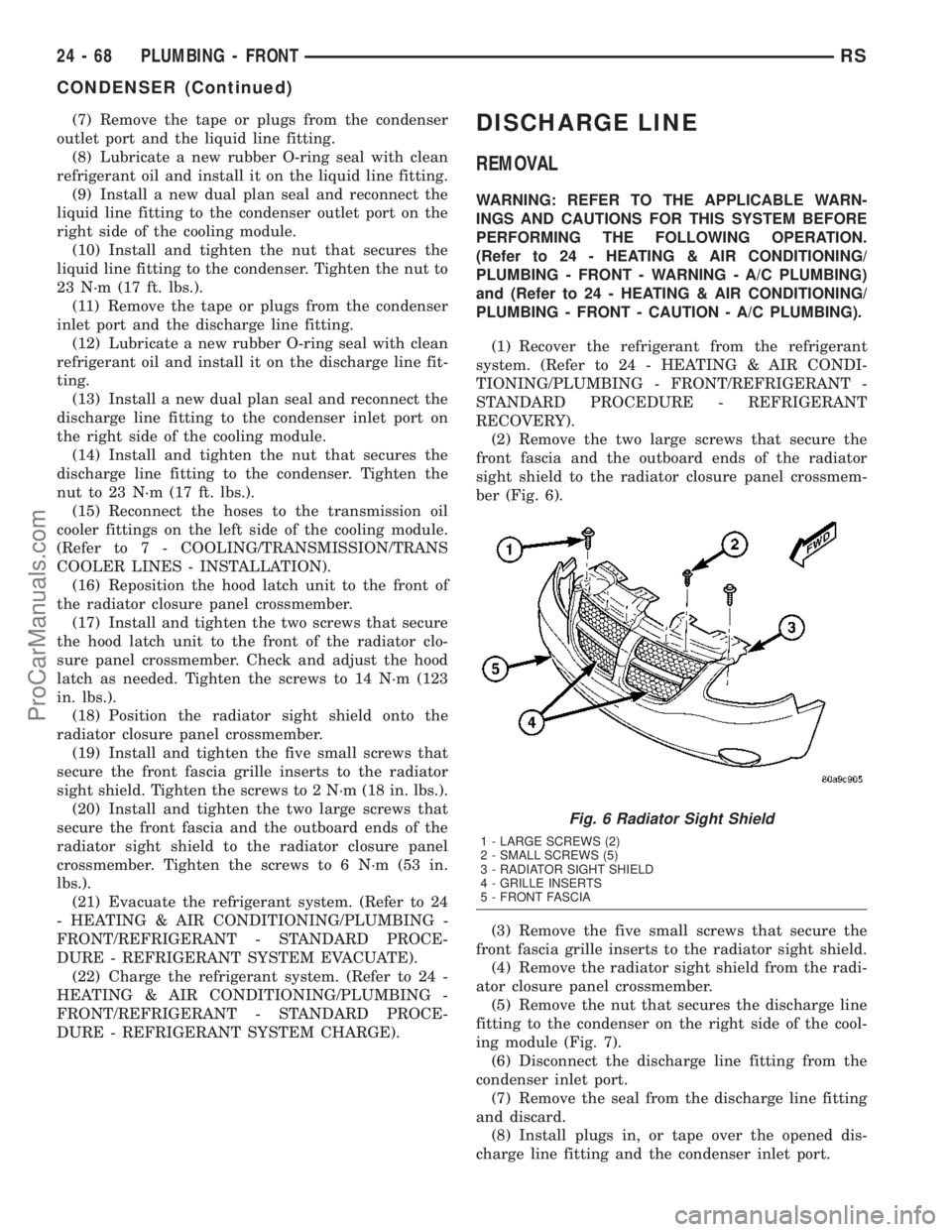
(2) Remove the two large screws that secure the
front fascia and the outboard ends of the radiator
sight shield to the radiator closure panel crossmem-
ber (Fig. 6).
(3) Remove the five small screws that secure the
front fascia grille inserts to the radiator sight shield.
(4) Remove the radiator sight shield from the radi-
ator closure panel crossmember.
(5) Remove the nut that secures the discharge line
fitting to the condenser on the right side of the cool-
ing module (Fig. 7).
(6) Disconnect the discharge line fitting from the
condenser inlet port.
(7) Remove the seal from the discharge line fitting
and discard.
(8) Install plugs in, or tape over the opened dis-
charge line fitting and the condenser inlet port.
Fig. 6 Radiator Sight Shield
1 - LARGE SCREWS (2)
2 - SMALL SCREWS (5)
3 - RADIATOR SIGHT SHIELD
4 - GRILLE INSERTS
5 - FRONT FASCIA
24 - 68 PLUMBING - FRONTRS
CONDENSER (Continued)
ProCarManuals.com
Page 2083 of 2177
K thermocouple. If a digital multimeter is not avail-
able, this tool is also available through the PSE pro-
gram.
NOTE: When connecting the service equipment
couplings to the refrigerant system service ports,
be certain that the valve of each coupling is fully
closed. This will reduce the amount of effort
required to make the connection.
(1) Remove the caps from the refrigerant system
service ports and attach a manifold gauge set or a
R-134a refrigerant recovery/recycling/charging sta-
tion that meets SAE Standard J2210 to the refriger-
ant system.
(2) Attach a clamp-on thermocouple to the liquid
line. The thermocouple must be placed as close to the
A/C pressure transducer as possible to accurately
observe liquid line temperature.
(3) Bring the refrigerant system up to operating
temperature and pressure. This is done by allowing
the engine to run at idle under the following condi-
tions for five minutes.
(a) Front windows are open.
(b) Transaxle in Park.
(c) Front heater-A/C controls set to outside air,
full cool, panel mode, blower high, and compressor
engaged.
(d) If the vehicle is so equipped, the rear heater-
A/C controls must be set to full cool and blower
high.
(4) Raise the liquid line (discharge) pressure to
about 1793 kPa (260 psi) by placing a piece of card-
board over part of the front side of the condenser. To
place the cardboard properly, remove the upper radi-
ator sight shield from the front fascia. Cover only
enough of the condenser to raise and maintain the
liquid line pressure at the specified level.
(5) Observe the liquid line (discharge) pressure
and liquid line temperature. Using the Charge Deter-
mination Chart (Fig. 31), determine whether the
refrigerant system is operating within the Proper
Charge Range.
(a) If the refrigerant system is operating in the
Undercharged area of the chart, add 0.057 kilo-
gram (0.125 pound or 2 ounces) of refrigerant to
the system.
(b) If the refrigerant system is operating in the
Overcharged area of the chart, reclaim 0.057 kilo-
gram (0.125 pound or 2 ounces) of refrigerant from
the system.
(6) Recheck the system charge level following each
refrigerant adjustment. Continue this process until
the system readings are in the Proper Charge Range
area on the Charge Determination Chart.DIAGNOSIS AND TESTING - REFRIGERANT
SYSTEM LEAKS
WARNING: REFER TO THE APPLICABLE WARN-
INGS AND CAUTIONS FOR THIS SYSTEM BEFORE
PERFORMING THE FOLLOWING OPERATION.
(Refer to 24 - HEATING & AIR CONDITIONING/
PLUMBING - FRONT - WARNING - A/C PLUMBING)
and (Refer to 24 - HEATING & AIR CONDITIONING/
PLUMBING - FRONT - CAUTION - A/C PLUMBING).
If the air conditioning system is not cooling prop-
erly, determine if the refrigerant system is fully-
charged. (Refer to 24 - HEATING & AIR
CONDITIONING/PLUMBING - FRONT/REFRIGER-
ANT - DIAGNOSIS AND TESTING - REFRIGER-
ANT SYSTEM CHARGE LEVEL).
If the refrigerant system is low or empty; a leak at
a refrigerant line, connector fitting, component, or
component seal is likely. While an oily residue on or
near refrigerant system lines, connector fittings, com-
ponents, or component seals can indicate the general
location of a possible refrigerant leak, the exact leak
location should be confirmed with an electronic leak
detector prior to component repair or replacement.
An electronic leak detector designed for R-134a
refrigerant is recommended for locating and confirm-
ing refrigerant system leaks. See the operating
instructions supplied by the equipment manufacturer
for proper care and use of this equipment.
To detect a leak in the refrigerant system, perform
one of the following procedures as indicated by the
results of the refrigerant system charge level test.
SYSTEM EMPTY
(1) Evacuate the refrigerant system. (Refer to 24 -
HEATING & AIR CONDITIONING/PLUMBING -
FRONT/REFRIGERANT - STANDARD PROCE-
DURE - REFRIGERANT SYSTEM EVACUATE).
(2) Connect and dispense 0.283 kilograms (0.625
pounds or 10 ounces) of R-134a refrigerant into the
evacuated refrigerant system. (Refer to 24 - HEAT-
ING & AIR CONDITIONING/PLUMBING - FRONT/
REFRIGERANT - STANDARD PROCEDURE -
REFRIGERANT SYSTEM CHARGE).
(3) Proceed to the SYSTEM LOW procedures.
SYSTEM LOW
(1) Position the vehicle in a wind-free work area.
This will aid in detecting small leaks.
(2) Bring the refrigerant system up to operating
temperature and pressure. This is done by allowing
the engine to run at idle under the following condi-
tions for five minutes, then turning the engine off.
(a) Front windows are open.
(b) Rear air conditioner Off (if equipped).
24 - 86 PLUMBING - FRONTRS
REFRIGERANT (Continued)
ProCarManuals.com