2003 CHRYSLER CARAVAN oil pressure
[x] Cancel search: oil pressurePage 1613 of 2177
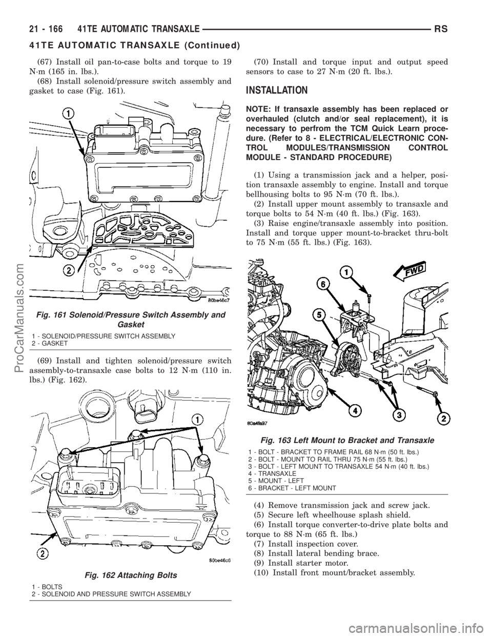
(67) Install oil pan-to-case bolts and torque to 19
N´m (165 in. lbs.).
(68) Install solenoid/pressure switch assembly and
gasket to case (Fig. 161).
(69) Install and tighten solenoid/pressure switch
assembly-to-transaxle case bolts to 12 N´m (110 in.
lbs.) (Fig. 162).(70) Install and torque input and output speed
sensors to case to 27 N´m (20 ft. lbs.).
INSTALLATION
NOTE: If transaxle assembly has been replaced or
overhauled (clutch and/or seal replacement), it is
necessary to perfrom the TCM Quick Learn proce-
dure. (Refer to 8 - ELECTRICAL/ELECTRONIC CON-
TROL MODULES/TRANSMISSION CONTROL
MODULE - STANDARD PROCEDURE)
(1) Using a transmission jack and a helper, posi-
tion transaxle assembly to engine. Install and torque
bellhousing bolts to 95 N´m (70 ft. lbs.).
(2) Install upper mount assembly to transaxle and
torque bolts to 54 N´m (40 ft. lbs.) (Fig. 163).
(3) Raise engine/transaxle assembly into position.
Install and torque upper mount-to-bracket thru-bolt
to 75 N´m (55 ft. lbs.) (Fig. 163).
(4) Remove transmission jack and screw jack.
(5) Secure left wheelhouse splash shield.
(6) Install torque converter-to-drive plate bolts and
torque to 88 N´m (65 ft. lbs.)
(7) Install inspection cover.
(8) Install lateral bending brace.
(9) Install starter motor.
(10) Install front mount/bracket assembly.
Fig. 161 Solenoid/Pressure Switch Assembly and
Gasket
1 - SOLENOID/PRESSURE SWITCH ASSEMBLY
2 - GASKET
Fig. 162 Attaching Bolts
1 - BOLTS
2 - SOLENOID AND PRESSURE SWITCH ASSEMBLY
Fig. 163 Left Mount to Bracket and Transaxle
1 - BOLT - BRACKET TO FRAME RAIL 68 N´m (50 ft. lbs.)
2 - BOLT - MOUNT TO RAIL THRU 75 N´m (55 ft. lbs.)
3 - BOLT - LEFT MOUNT TO TRANSAXLE 54 N´m (40 ft. lbs.)
4 - TRANSAXLE
5 - MOUNT - LEFT
6 - BRACKET - LEFT MOUNT
21 - 166 41TE AUTOMATIC TRANSAXLERS
41TE AUTOMATIC TRANSAXLE (Continued)
ProCarManuals.com
Page 1615 of 2177

(20) Connect solenoid/pressure switch assembly
(Fig. 166).
(21) Connect transmission range sensor connector
(Fig. 166).
(22) Connect input and output speed sensor con-
nectors (Fig. 166).
(23) Remove plugs and install transaxle oil cooler
line service splice kit. Refer to instructions included
with kit.
(24) Remove plug and Install fluid level indicator/
tube assembly.(25) Install coolant recovery bottle (Fig. 167).
(26) Install battery shield.
(27) Connect battery cables.
(28) Fill transaxle with suitable amount of ATF+4
(Automatic Transmission FluidÐType 9602). (Refer
to 21 - TRANSMISSION/TRANSAXLE/AUTOMATIC
- 41TE/FLUID - STANDARD PROCEDURE)
Fig. 166 Component Connector Location - Typical
1 - SOLENOID/PRESSURE SWITCH ASSY. CONNECTOR
2 - INPUT SPEED SENSOR CONNECTOR
3 - OUTPUT SPEED SENSOR CONNECTOR
4 - TRANSMISSION RANGE SENSOR CONNECTOR
Fig. 167 Coolant Recovery Bottle
1 - UPPER BOLT ATTACHING TO BATTERY TRAY
2 - COOLANT RECOVERY CONTAINER
3 - UPPER BOLT
4 - HOSE
5 - LOWER BOLT (QTY. 2)
6 - LEFT SIDE FRAME RAIL
21 - 168 41TE AUTOMATIC TRANSAXLERS
41TE AUTOMATIC TRANSAXLE (Continued)
ProCarManuals.com
Page 1628 of 2177
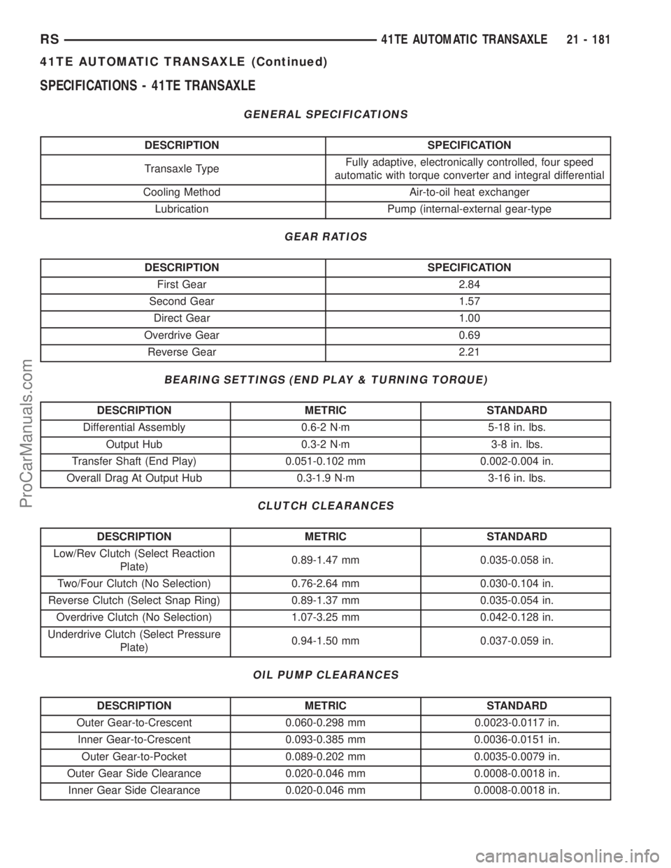
SPECIFICATIONS - 41TE TRANSAXLE
GENERAL SPECIFICATIONS
DESCRIPTION SPECIFICATION
Transaxle TypeFully adaptive, electronically controlled, four speed
automatic with torque converter and integral differential
Cooling Method Air-to-oil heat exchanger
Lubrication Pump (internal-external gear-type
GEAR RATIOS
DESCRIPTION SPECIFICATION
First Gear 2.84
Second Gear 1.57
Direct Gear 1.00
Overdrive Gear 0.69
Reverse Gear 2.21
BEARING SETTINGS (END PLAY & TURNING TORQUE)
DESCRIPTION METRIC STANDARD
Differential Assembly 0.6-2 N´m 5-18 in. lbs.
Output Hub 0.3-2 N´m 3-8 in. lbs.
Transfer Shaft (End Play) 0.051-0.102 mm 0.002-0.004 in.
Overall Drag At Output Hub 0.3-1.9 N´m 3-16 in. lbs.
CLUTCH CLEARANCES
DESCRIPTION METRIC STANDARD
Low/Rev Clutch (Select Reaction
Plate)0.89-1.47 mm 0.035-0.058 in.
Two/Four Clutch (No Selection) 0.76-2.64 mm 0.030-0.104 in.
Reverse Clutch (Select Snap Ring) 0.89-1.37 mm 0.035-0.054 in.
Overdrive Clutch (No Selection) 1.07-3.25 mm 0.042-0.128 in.
Underdrive Clutch (Select Pressure
Plate)0.94-1.50 mm 0.037-0.059 in.
OIL PUMP CLEARANCES
DESCRIPTION METRIC STANDARD
Outer Gear-to-Crescent 0.060-0.298 mm 0.0023-0.0117 in.
Inner Gear-to-Crescent 0.093-0.385 mm 0.0036-0.0151 in.
Outer Gear-to-Pocket 0.089-0.202 mm 0.0035-0.0079 in.
Outer Gear Side Clearance 0.020-0.046 mm 0.0008-0.0018 in.
Inner Gear Side Clearance 0.020-0.046 mm 0.0008-0.0018 in.
RS41TE AUTOMATIC TRANSAXLE21 - 181
41TE AUTOMATIC TRANSAXLE (Continued)
ProCarManuals.com
Page 1629 of 2177
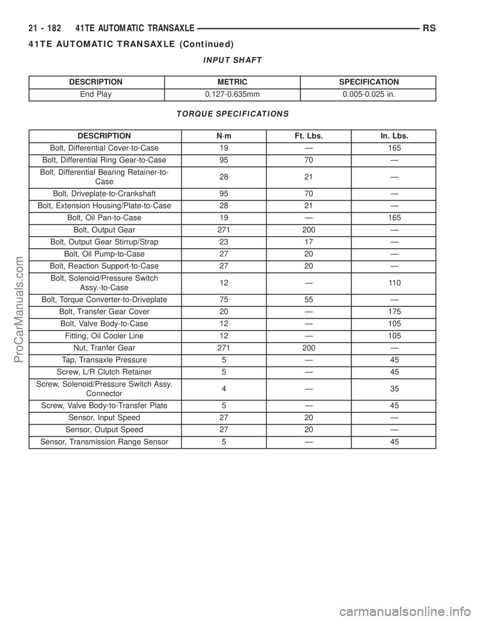
INPUT SHAFT
DESCRIPTION METRIC SPECIFICATION
End Play 0.127-0.635mm 0.005-0.025 in.
TORQUE SPECIFICATIONS
DESCRIPTION N´m Ft. Lbs. In. Lbs.
Bolt, Differential Cover-to-Case 19 Ð 165
Bolt, Differential Ring Gear-to-Case 95 70 Ð
Bolt, Differential Bearing Retainer-to-
Case28 21 Ð
Bolt, Driveplate-to-Crankshaft 95 70 Ð
Bolt, Extension Housing/Plate-to-Case 28 21 Ð
Bolt, Oil Pan-to-Case 19 Ð 165
Bolt, Output Gear 271 200 Ð
Bolt, Output Gear Stirrup/Strap 23 17 Ð
Bolt, Oil Pump-to-Case 27 20 Ð
Bolt, Reaction Support-to-Case 27 20 Ð
Bolt, Solenoid/Pressure Switch
Assy.-to-Case12 Ð 110
Bolt, Torque Converter-to-Driveplate 75 55 Ð
Bolt, Transfer Gear Cover 20 Ð 175
Bolt, Valve Body-to-Case 12 Ð 105
Fitting, Oil Cooler Line 12 Ð 105
Nut, Tranfer Gear 271 200 Ð
Tap, Transaxle Pressure 5 Ð 45
Screw, L/R Clutch Retainer 5 Ð 45
Screw, Solenoid/Pressure Switch Assy.
Connector4Ð35
Screw, Valve Body-to-Transfer Plate 5 Ð 45
Sensor, Input Speed 27 20 Ð
Sensor, Output Speed 27 20 Ð
Sensor, Transmission Range Sensor 5 Ð 45
21 - 182 41TE AUTOMATIC TRANSAXLERS
41TE AUTOMATIC TRANSAXLE (Continued)
ProCarManuals.com
Page 1630 of 2177
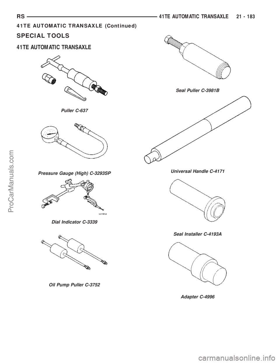
SPECIAL TOOLS
41TE AUTOMATIC TRANSAXLE
Puller C-637
Pressure Gauge (High) C-3293SP
Dial Indicator C-3339
Oil Pump Puller C-3752
Seal Puller C-3981B
Universal Handle C-4171
Seal Installer C-4193A
Adapter C-4996
RS41TE AUTOMATIC TRANSAXLE21 - 183
41TE AUTOMATIC TRANSAXLE (Continued)
ProCarManuals.com
Page 1649 of 2177
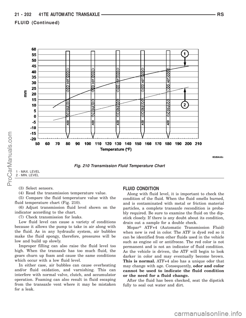
(3) Select sensors.
(4) Read the transmission temperature value.
(5) Compare the fluid temperature value with the
fluid temperature chart (Fig. 210).
(6) Adjust transmission fluid level shown on the
indicator according to the chart.
(7) Check transmission for leaks.
Low fluid level can cause a variety of conditions
because it allows the pump to take in air along with
the fluid. As in any hydraulic system, air bubbles
make the fluid spongy, therefore, pressures will be
low and build up slowly.
Improper filling can also raise the fluid level too
high. When the transaxle has too much fluid, the
gears churn up foam and cause the same conditions
which occur with a low fluid level.
In either case, air bubbles can cause overheating
and/or fluid oxidation, and varnishing. This can
interfere with normal valve, clutch, and accumulator
operation. Foaming can also result in fluid escaping
from the transaxle vent where it may be mistaken
for a leak.FLUID CONDITION
Along with fluid level, it is important to check the
condition of the fluid. When the fluid smells burned,
and is contaminated with metal or friction material
particles, a complete transaxle recondition is proba-
bly required. Be sure to examine the fluid on the dip-
stick closely. If there is any doubt about its condition,
drain out a sample for a double check.
MopartATF+4 (Automatic Transmission Fluid)
when new is red in color. The ATF is dyed red so it
can be identified from other fluids used in the vehicle
such as engine oil or antifreeze. The red color is not
permanent and is not an indicator of fluid condition.
As the vehicle is driven, the ATF will begin to look
darker in color and may eventually become brown.
This is normal.ATF+4 also has a unique odor that
may change with age. Consequently,odor and color
cannot be used to indicate the fluid condition
or the need for a fluid change.
After the fluid has been checked, seat the dipstick
fully to seal out water and dirt.
Fig. 210 Transmission Fluid Temperature Chart
1 - MAX. LEVEL
2 - MIN. LEVEL
21 - 202 41TE AUTOMATIC TRANSAXLERS
FLUID (Continued)
ProCarManuals.com
Page 1692 of 2177
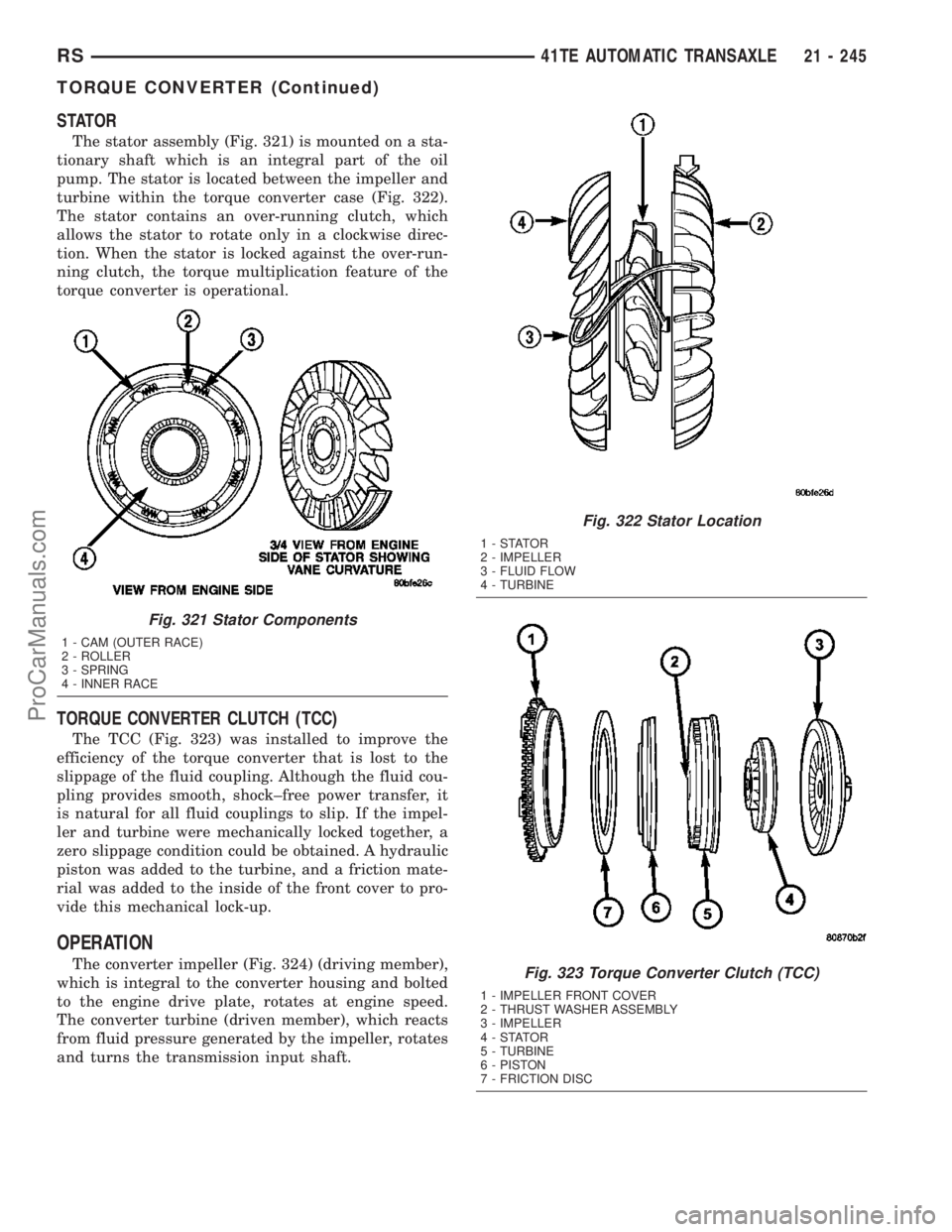
STATOR
The stator assembly (Fig. 321) is mounted on a sta-
tionary shaft which is an integral part of the oil
pump. The stator is located between the impeller and
turbine within the torque converter case (Fig. 322).
The stator contains an over-running clutch, which
allows the stator to rotate only in a clockwise direc-
tion. When the stator is locked against the over-run-
ning clutch, the torque multiplication feature of the
torque converter is operational.
TORQUE CONVERTER CLUTCH (TCC)
The TCC (Fig. 323) was installed to improve the
efficiency of the torque converter that is lost to the
slippage of the fluid coupling. Although the fluid cou-
pling provides smooth, shock±free power transfer, it
is natural for all fluid couplings to slip. If the impel-
ler and turbine were mechanically locked together, a
zero slippage condition could be obtained. A hydraulic
piston was added to the turbine, and a friction mate-
rial was added to the inside of the front cover to pro-
vide this mechanical lock-up.
OPERATION
The converter impeller (Fig. 324) (driving member),
which is integral to the converter housing and bolted
to the engine drive plate, rotates at engine speed.
The converter turbine (driven member), which reacts
from fluid pressure generated by the impeller, rotates
and turns the transmission input shaft.
Fig. 321 Stator Components
1 - CAM (OUTER RACE)
2 - ROLLER
3 - SPRING
4 - INNER RACE
Fig. 322 Stator Location
1-STATOR
2 - IMPELLER
3 - FLUID FLOW
4 - TURBINE
Fig. 323 Torque Converter Clutch (TCC)
1 - IMPELLER FRONT COVER
2 - THRUST WASHER ASSEMBLY
3 - IMPELLER
4-STATOR
5 - TURBINE
6 - PISTON
7 - FRICTION DISC
RS41TE AUTOMATIC TRANSAXLE21 - 245
TORQUE CONVERTER (Continued)
ProCarManuals.com
Page 1693 of 2177
TURBINE
As the fluid that was put into motion by the impel-
ler blades strikes the blades of the turbine, some of
the energy and rotational force is transferred into the
turbine and the input shaft. This causes both of them
(turbine and input shaft) to rotate in a clockwise
direction following the impeller. As the fluid is leav-
ing the trailing edges of the turbine's blades it con-
tinues in a ªhinderingº direction back toward the
impeller. If the fluid is not redirected before it strikes
the impeller, it will strike the impeller in such a
direction that it would tend to slow it down.
STATOR
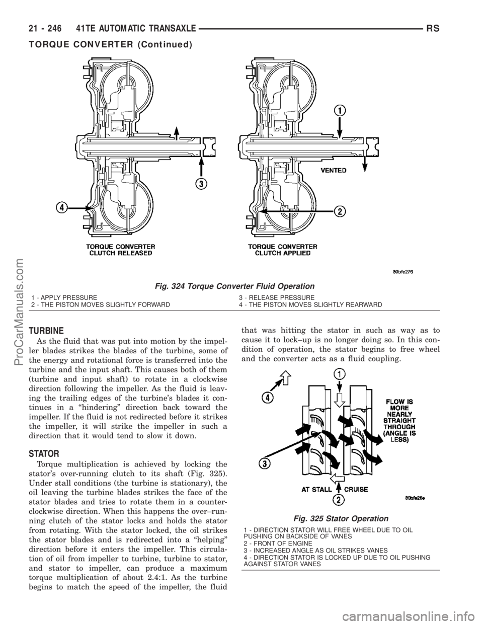
Torque multiplication is achieved by locking the
stator's over-running clutch to its shaft (Fig. 325).
Under stall conditions (the turbine is stationary), the
oil leaving the turbine blades strikes the face of the
stator blades and tries to rotate them in a counter-
clockwise direction. When this happens the over±run-
ning clutch of the stator locks and holds the stator
from rotating. With the stator locked, the oil strikes
the stator blades and is redirected into a ªhelpingº
direction before it enters the impeller. This circula-
tion of oil from impeller to turbine, turbine to stator,
and stator to impeller, can produce a maximum
torque multiplication of about 2.4:1. As the turbine
begins to match the speed of the impeller, the fluidthat was hitting the stator in such as way as to
cause it to lock±up is no longer doing so. In this con-
dition of operation, the stator begins to free wheel
and the converter acts as a fluid coupling.
Fig. 324 Torque Converter Fluid Operation
1 - APPLY PRESSURE 3 - RELEASE PRESSURE
2 - THE PISTON MOVES SLIGHTLY FORWARD 4 - THE PISTON MOVES SLIGHTLY REARWARD
Fig. 325 Stator Operation
1 - DIRECTION STATOR WILL FREE WHEEL DUE TO OIL
PUSHING ON BACKSIDE OF VANES
2 - FRONT OF ENGINE
3 - INCREASED ANGLE AS OIL STRIKES VANES
4 - DIRECTION STATOR IS LOCKED UP DUE TO OIL PUSHING
AGAINST STATOR VANES
21 - 246 41TE AUTOMATIC TRANSAXLERS
TORQUE CONVERTER (Continued)
ProCarManuals.com