2003 CHRYSLER CARAVAN coolant
[x] Cancel search: coolantPage 2054 of 2177
(2) Drain the engine cooling system. (Refer to 7 -
COOLING - STANDARD PROCEDURE - COOLING
SYSTEM DRAIN).
(3) Disconnect and isolate the battery negative
cable.
(4) Raise and support the vehicle.
(5) Disconnect the underbody refrigerant line seal-
ing plate from the rear heater-A/C unit evaporator
extension line sealing plate that extends through the
rear floor panel behind the right rear wheel housing
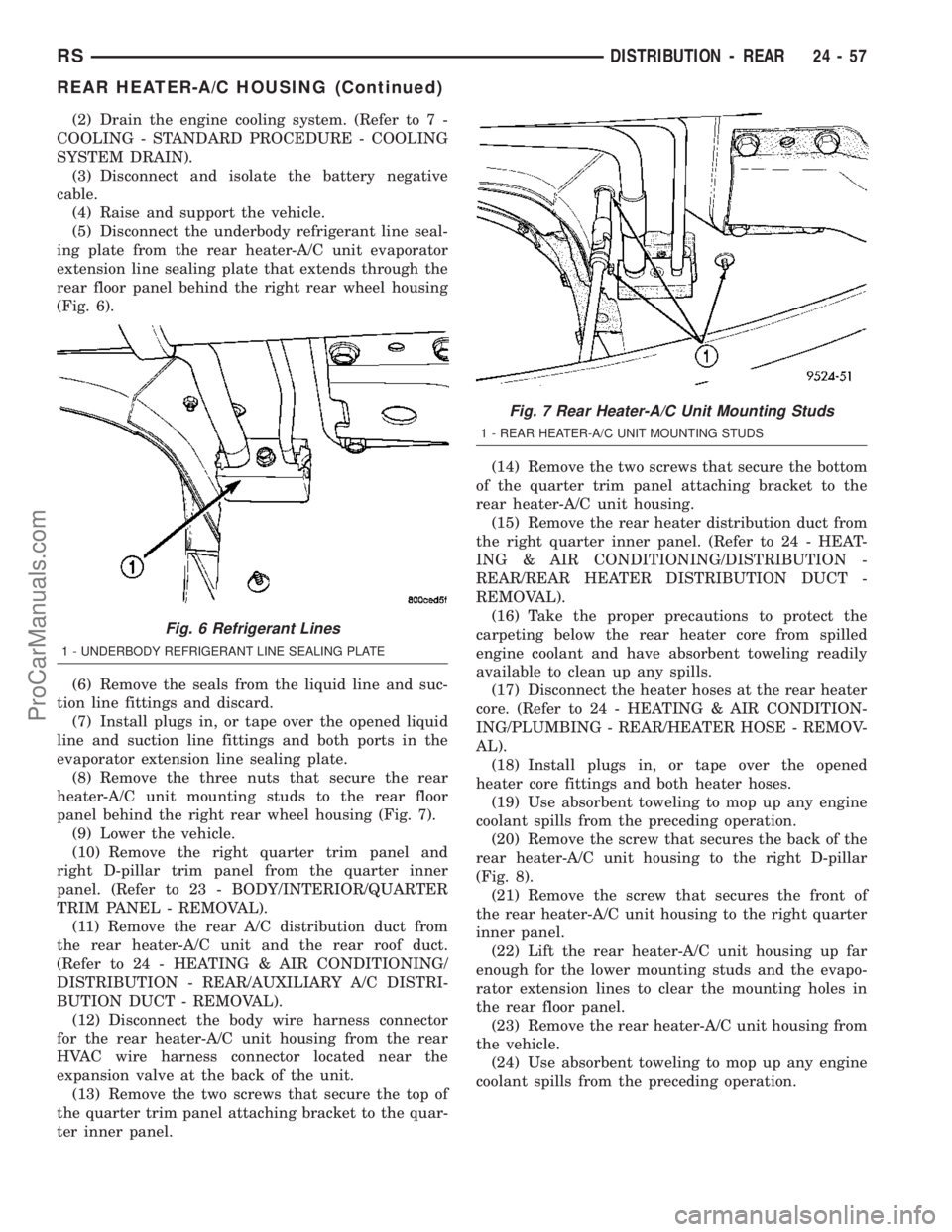
(Fig. 6).
(6) Remove the seals from the liquid line and suc-
tion line fittings and discard.
(7) Install plugs in, or tape over the opened liquid
line and suction line fittings and both ports in the
evaporator extension line sealing plate.
(8) Remove the three nuts that secure the rear
heater-A/C unit mounting studs to the rear floor
panel behind the right rear wheel housing (Fig. 7).
(9) Lower the vehicle.
(10) Remove the right quarter trim panel and
right D-pillar trim panel from the quarter inner
panel. (Refer to 23 - BODY/INTERIOR/QUARTER
TRIM PANEL - REMOVAL).
(11) Remove the rear A/C distribution duct from
the rear heater-A/C unit and the rear roof duct.
(Refer to 24 - HEATING & AIR CONDITIONING/
DISTRIBUTION - REAR/AUXILIARY A/C DISTRI-
BUTION DUCT - REMOVAL).
(12) Disconnect the body wire harness connector
for the rear heater-A/C unit housing from the rear
HVAC wire harness connector located near the
expansion valve at the back of the unit.
(13) Remove the two screws that secure the top of
the quarter trim panel attaching bracket to the quar-
ter inner panel.(14) Remove the two screws that secure the bottom
of the quarter trim panel attaching bracket to the
rear heater-A/C unit housing.
(15) Remove the rear heater distribution duct from
the right quarter inner panel. (Refer to 24 - HEAT-
ING & AIR CONDITIONING/DISTRIBUTION -
REAR/REAR HEATER DISTRIBUTION DUCT -
REMOVAL).
(16) Take the proper precautions to protect the
carpeting below the rear heater core from spilled
engine coolant and have absorbent toweling readily
available to clean up any spills.
(17) Disconnect the heater hoses at the rear heater
core. (Refer to 24 - HEATING & AIR CONDITION-
ING/PLUMBING - REAR/HEATER HOSE - REMOV-
AL).
(18) Install plugs in, or tape over the opened
heater core fittings and both heater hoses.
(19) Use absorbent toweling to mop up any engine
coolant spills from the preceding operation.
(20) Remove the screw that secures the back of the
rear heater-A/C unit housing to the right D-pillar
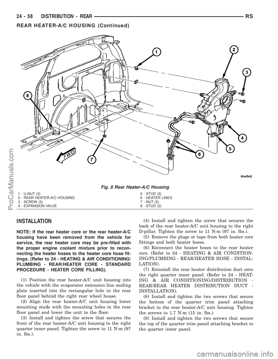
(Fig. 8).
(21) Remove the screw that secures the front of
the rear heater-A/C unit housing to the right quarter
inner panel.
(22) Lift the rear heater-A/C unit housing up far
enough for the lower mounting studs and the evapo-
rator extension lines to clear the mounting holes in
the rear floor panel.
(23) Remove the rear heater-A/C unit housing from
the vehicle.
(24) Use absorbent toweling to mop up any engine
coolant spills from the preceding operation.
Fig. 6 Refrigerant Lines
1 - UNDERBODY REFRIGERANT LINE SEALING PLATE
Fig. 7 Rear Heater-A/C Unit Mounting Studs
1 - REAR HEATER-A/C UNIT MOUNTING STUDS
RSDISTRIBUTION - REAR24-57
REAR HEATER-A/C HOUSING (Continued)
ProCarManuals.com
Page 2055 of 2177
INSTALLATION
NOTE: If the rear heater core or the rear heater-A/C
housing have been removed from the vehicle for
service, the rear heater core may be pre-filled with
the proper engine coolant mixture prior to recon-
necting the heater hoses to the heater core hose fit-
tings. (Refer to 24 - HEATING & AIR CONDITIONING/
PLUMBING - REAR/HEATER CORE - STANDARD
PROCEDURE - HEATER CORE FILLING).
(1) Position the rear heater-A/C unit housing into
the vehicle with the evaporator extension line sealing
plate inserted into the rectangular hole in the rear
floor panel behind the right rear wheel house.
(2) Align the rear heater-A/C unit housing lower
mounting studs with the mounting holes in the rear
floor panel and lower the unit to the floor.
(3) Install and tighten the screw that secures the
front of the rear heater-A/C unit housing to the right
quarter inner panel. Tighten the screw to 11 N´m (97
in. lbs.).(4) Install and tighten the screw that secures the
back of the rear heater-A/C unit housing to the right
D-pillar. Tighten the screw to 11 N´m (97 in. lbs.).
(5) Remove the plugs or tape from both heater core
fittings and both heater hoses.
(6) Reconnect the heater hoses to the rear heater
core. (Refer to 24 - HEATING & AIR CONDITION-
ING/PLUMBING - REAR/HEATER HOSE - INSTAL-
LATION).
(7) Reinstall the rear heater distribution duct onto
the right quarter inner panel. (Refer to 24 - HEAT-
ING & AIR CONDITIONING/DISTRIBUTION -
REAR/REAR HEATER DISTRIBUTION DUCT -
INSTALLATION).
(8) Install and tighten the two screws that secure
the bottom of the quarter trim panel attaching
bracket to the rear heater-A/C unit housing. Tighten
the screws to 1.7 N´m (15 in. lbs.).
(9) Install and tighten the two screws that secure
the top of the quarter trim panel attaching bracket to
the quarter inner panel.
Fig. 8 Rear Heater-A/C Housing
1 - U-NUT (3)
2 - REAR HEATER-A/C HOUSING
3 - SCREW (3)
4 - EXPANSION VALVE5 - STUD (3)
6 - HEATER LINES
7 - NUT (5)
8 - STUD (2)
24 - 58 DISTRIBUTION - REARRS
REAR HEATER-A/C HOUSING (Continued)
ProCarManuals.com
Page 2058 of 2177
PLUMBING - FRONT
WARNING
WARNING
WARNING:: THE ENGINE COOLING SYSTEM IS
DESIGNED TO DEVELOP INTERNAL PRESSURES
OF 97 TO 123 KILOPASCALS (14 TO 18 POUNDS
PER SQUARE INCH). DO NOT REMOVE OR
LOOSEN THE COOLANT PRESSURE CAP, CYLIN-
DER BLOCK DRAIN PLUGS, RADIATOR DRAIN,
RADIATOR HOSES, HEATER HOSES, OR HOSE
CLAMPS WHILE THE SYSTEM IS HOT AND UNDER
PRESSURE. FAILURE TO OBSERVE THIS WARNING
CAN RESULT IN SERIOUS BURNS FROM THE
HEATED ENGINE COOLANT. ALLOW THE VEHICLE
TO COOL FOR A MINIMUM OF 15 MINUTES
BEFORE OPENING THE COOLING SYSTEM FOR
SERVICE.
WARNING: THE ENGINE COOLING SYSTEM CON-
TAINS ANTIFREEZE. ANTIFREEZE IS AN ETHYLENE
GLYCOL BASED COOLANT AND IS HARMFUL IF
SWALLOWED OR IF THE VAPORS ARE INHALED. IF
SWALLOWED, DRINK TWO GLASSES OF WATER
AND INDUCE VOMITING. IF VAPORS ARE INHALED,
MOVE TO AN AREA FOR FRESH AIR. SEEK MEDI-
CAL ATTENTION IMMEDIATELY. DO NOT STORE IN
OPEN OR UNMARKED CONTAINERS. WASH SKIN
AND CLOTHING THOROUGHLY AFTER COMING IN
CONTACT WITH ETHYLENE GLYCOL. KEEP OUT
OF REACH OF CHILDREN.
WARNING: DISPOSE OF ETHYLENE GLYCOL
BASED COOLANT PROPERLY. CONTACT YOUR
DEALER OR A LOCAL GOVERNMENT AGENCY FOR
THE LOCATION OF AN APPROVED ETHYLENE GLY-
COL COLLECTION AND/OR RECYCLING CENTER IN
YOUR AREA.
WARNING - A/C PLUMBING
WARNING:: THE AIR CONDITIONING SYSTEM CON-
TAINS REFRIGERANT UNDER HIGH PRESSURE.
SEVERE PERSONAL INJURY MAY RESULT FROM
IMPROPER SERVICE PROCEDURES. REPAIRS
SHOULD ONLY BE PERFORMED BY QUALIFIED
SERVICE PERSONNEL.
WARNING: AVOID BREATHING THE REFRIGERANT
AND REFRIGERANT OIL VAPOR OR MIST. EXPO-
SURE MAY IRRITATE THE EYES, NOSE, AND/ORTHROAT. WEAR EYE PROTECTION WHEN SERVIC-
ING THE AIR CONDITIONING REFRIGERANT SYS-
TEM. SERIOUS EYE INJURY CAN RESULT FROM
DIRECT CONTACT WITH THE REFRIGERANT. IF
EYE CONTACT OCCURS, SEEK MEDICAL ATTEN-
TION IMMEDIATELY.
WARNING: DO NOT EXPOSE THE REFRIGERANT
TO OPEN FLAME. POISONOUS GAS IS CREATED
WHEN REFRIGERANT IS BURNED. AN ELEC-
TRONIC LEAK DETECTOR IS RECOMMENDED.
WARNING: IF ACCIDENTAL SYSTEM DISCHARGE
OCCURS, VENTILATE THE WORK AREA BEFORE
RESUMING SERVICE. LARGE AMOUNTS OF
REFRIGERANT RELEASED IN A CLOSED WORK
AREA WILL DISPLACE THE OXYGEN AND CAUSE
SUFFOCATION.
WARNING: THE EVAPORATION RATE OF R-134a
REFRIGERANT AT AVERAGE TEMPERATURE AND
ALTITUDE IS EXTREMELY HIGH. AS A RESULT,
ANYTHING THAT COMES IN CONTACT WITH THE
REFRIGERANT WILL FREEZE. ALWAYS PROTECT
THE SKIN OR DELICATE OBJECTS FROM DIRECT
CONTACT WITH THE REFRIGERANT.
WARNING: THE R-134a SERVICE EQUIPMENT OR
THE VEHICLE REFRIGERANT SYSTEM SHOULD
NOT BE PRESSURE TESTED OR LEAK TESTED
WITH COMPRESSED AIR. SOME MIXTURES OF AIR
AND R-134a HAVE BEEN SHOWN TO BE COMBUS-
TIBLE AT ELEVATED PRESSURES. THESE MIX-
TURES ARE POTENTIALLY DANGEROUS, AND MAY
RESULT IN FIRE OR EXPLOSION CAUSING INJURY
OR PROPERTY DAMAGE.
CAUTION - A/C PLUMBING
CAUTION:: Liquid refrigerant is corrosive to metal
surfaces. Follow the operating instructions supplied
with the service equipment being used.
CAUTION: Never add R-12 to a refrigerant system
designed to use R-134a. Damage to the system will
result.
CAUTION: R-12 refrigerant oil must not be mixed
with R-134a refrigerant oil. They are not compatible.
RSPLUMBING - FRONT24-61
ProCarManuals.com
Page 2071 of 2177
(9) Install plugs in, or tape over the opened liquid
line fitting and the filter-drier outlet port.
(10) Remove the nut that secures the suction line
and liquid line fittings to the stud on the expansion
valve.
(11) Disconnect the suction line and liquid line fit-
tings from the expansion valve and move the lines
out of the way.
(12) Remove the seals from the suction line and
liquid line fittings and discard.
(13) Install plugs in, or tape over the opened suc-
tion line and liquid line fittings and both expansion
valve ports.
(14) Remove the two screws that secure the expan-
sion valve to the evaporator tube tapping plate.
(15) Disconnect the HVAC wire harness connector
for the evaporator temperature sensor from the sen-
sor on the top of the expansion valve.
(16) Remove the expansion valve from the evapo-
rator inlet and outlet tube fittings.
(17) Remove the seals from the evaporator inlet
and outlet tube fittings and discard.
(18) Install plugs in, or tape over the opened evap-
orator inlet and outlet tube fittings and both expan-
sion valve ports.
INSTALLATION
(1) Remove the tape or plugs from the evaporator
inlet and outlet tube fittings and both ports on the
back of the expansion valve.
(2) Lubricate new rubber O-ring seals with clean
refrigerant oil and install them on the evaporator
inlet and outlet tube fittings.
(3) Position the expansion valve onto the evapora-
tor inlet and outlet tube fittings.
(4) Install and tighten the two screws that secure
the expansion valve to the evaporator tube tapping
plate plate. Tighten the screws to 11 N´m (97 in.
lbs.).
(5) Reconnect the HVAC wire harness connector
for the evaporator temperature sensor to the sensor
connector receptacle on the top of the expansion
valve.
(6) Remove the tape or plugs from the front liquid
line rear section and suction line fittings for the
expansion valve and both ports on the front of the
expansion valve.
(7) Lubricate new rubber O-ring seals with clean
refrigerant oil and install them on the front liquid
line rear section and suction line fittings for the
expansion valve.
(8) Reconnect the liquid line and suction line fit-
tings to the expansion valve.
(9) Install and tighten the nut that secures the
suction line and liquid line fittings to the stud on theexpansion valve. Tighten the nut to 23 N´m (17 ft.
lbs.).
(10) Remove the tape or plugs from the liquid line
rear section fitting for the filter-drier and the filter-
drier outlet port.
(11) Lubricate a new rubber O-ring seal with clean
refrigerant oil and install it on the liquid line fitting.
(12) Reconnect the liquid line fitting to the filter-
drier outlet port on the top of the filter-drier.
(13) Install and tighten the screw that secures the
liquid line fitting to the filter-drier. Tighten the screw
to 11 N´m (100 in. lbs.).
(14) Reconnect the headlamp and dash wire har-
ness connector for the A/C pressure transducer to the
transducer on the front liquid line rear section.
(15) Reconnect the drain tube to the wiper module
drain on the right side of the engine compartment.
(16) Reinstall the air cleaner housing into the
right side of the engine compartment.
(17) Reconnect the battery negative cable.
(18) Evacuate the refrigerant system. (Refer to 24
- HEATING & AIR CONDITIONING/PLUMBING -
FRONT/REFRIGERANT - STANDARD PROCE-
DURE - REFRIGERANT SYSTEM EVACUATE).
(19) Charge the refrigerant system. (Refer to 24 -
HEATING & AIR CONDITIONING/PLUMBING -
FRONT/REFRIGERANT - STANDARD PROCE-
DURE - REFRIGERANT SYSTEM CHARGE).
HEATER CORE
DESCRIPTION
The heater core is located in the distribution hous-
ing of the heater-A/C unit, under the instrument
panel. It is a heat exchanger made of rows of tubes
and fins. One end of the core is fitted with a molded
plastic tank that includes integral heater core inlet
and outlet ports. The removable heater core tubes
are held in place these ports by a sealing plate
secured with a screw to the heater core tank. This
removable heater core tube arrangement allows the
heater core to be serviced without removing the heat-
er-A/C unit housing from the vehicle. The heater core
cannot be repaired and, if faulty or damaged, it must
be replaced.
OPERATION
Engine coolant is circulated through heater hoses
to the heater core at all times. As the coolant flows
through the heater core, heat removed from the
engine is transferred to the heater core fins and
tubes. Air directed through the heater core picks up
the heat from the heater core fins. The blend air door
allows control of the heater output air temperature
by controlling how much of the air flowing through
24 - 74 PLUMBING - FRONTRS
EXPANSION VALVE (Continued)
ProCarManuals.com
Page 2073 of 2177
(12) Use absorbent toweling to mop up any engine
coolant spills from the preceding operation.
(13) Pull both heater core tubes simultaneously
slightly away from the distribution housing and rear-
ward far enough to disengage the engine compart-
ment ends of the tubes from the dash panel seal.
(14) Remove the heater core tubes and sealing
plate as a unit from beneath the instrument panel.
(15) Use absorbent toweling to clean up any
engine coolant spills from the preceding operation.
REMOVAL - HEATER CORE
WARNING: REFER TO THE APPLICABLE WARN-
INGS AND CAUTIONS FOR THIS SYSTEM BEFORE
PERFORMING THE FOLLOWING OPERATION.
(Refer to 24 - HEATING & AIR CONDITIONING/
PLUMBING FRONT - WARNING - HEATER PLUMB-
ING).
WARNING: ON VEHICLES EQUIPPED WITH AIR-
BAGS, DISABLE THE AIRBAG SYSTEM BEFORE
ATTEMPTING ANY STEERING WHEEL, STEERING
COLUMN, OR INSTRUMENT PANEL COMPONENT
DIAGNOSIS OR SERVICE. DISCONNECT AND ISO-
LATE THE BATTERY NEGATIVE (GROUND) CABLE,
THEN WAIT TWO MINUTES FOR THE AIRBAG SYS-
TEM CAPACITOR TO DISCHARGE BEFORE PER-
FORMING FURTHER DIAGNOSIS OR SERVICE. THIS
IS THE ONLY SURE WAY TO DISABLE THE AIRBAG
SYSTEM. FAILURE TO TAKE THE PROPER PRE-
CAUTIONS COULD RESULT IN ACCIDENTAL AIR-
BAG DEPLOYMENT AND POSSIBLE PERSONAL
INJURY.
(1) Drain the engine cooling system. (Refer to 7 -
COOLING - STANDARD PROCEDURE - COOLING
SYSTEM DRAIN).
(2) Disconnect and isolate the battery negative
cable.
(3) Remove the silencer boot fasteners located
around the base of the lower steering shaft from the
dash panel so that it may be pushed aside.
(4) Remove the brake lamp switch from its mount-
ing bracket. (Refer to 8 - ELECTRICAL/LAMPS/
LIGHTING - EXTERIOR/BRAKE LAMP SWITCH -
REMOVAL).
(5) Disconnect the power brake booster input rod
(push rod) from the pin on the brake pedal arm.
(Refer to 5 - BRAKES - ABS/HYDRAULIC/ME-
CHANICAL/POWER BRAKE BOOSTER - REMOV-
AL).
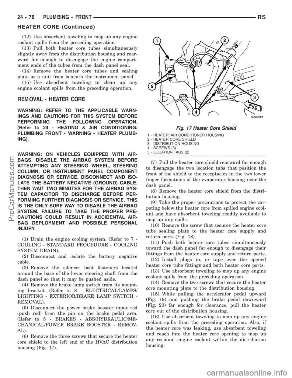
(6) Remove the three screws that secure the heater
core shield to the left end of the HVAC distribution
housing (Fig. 17).(7) Pull the heater core shield rearward far enough
to disengage the two location tabs that position the
front of the shield to the receptacles in the two lower
finger formations of the evaporator housing near the
dash panel.
(8) Remove the heater core shield from the distri-
bution housing.
(9) Take the proper precautions to protect the car-
peting below the heater core from spilled engine cool-
ant and have absorbent toweling readily available to
mop up any spills.
(10) Remove the screw that secures the heater core
tube sealing plate to the heater core supply and
return ports (Fig. 18).
(11) Push both heater core tubes simultaneously
toward the dash panel far enough to disengage their
fittings from the heater core supply and return ports.
(12) Install plugs in, or tape over the opened
heater core tube fittings and both heater core ports.
(13) Use absorbent toweling to mop up any engine
coolant spills from the preceding operation.
(14) Remove the two screws that secure the heater
core mounting plate to the distribution housing.
(15) While pulling the accelerator pedal upward
(Fig. 19) and pushing the brake pedal downward
(Fig. 20) far enough for clearance, pull the heater
core out of the distribution housing.
(16) Use absorbent toweling to mop up any engine
coolant spills from the preceding operation. Also, if
the heater core was leaking, use absorbent toweling
and reach into the heater core opening to mop up
any residual engine coolant within the distribution
housing.
Fig. 17 Heater Core Shield
1 - HEATER/ AIR CONDITIONER HOUSING
2 - HEATER CORE SHIELD
3 - DISTRIBUTION HOUSING
4 - SCREWS (3)
5 - LOCATION TABS (2)
24 - 76 PLUMBING - FRONTRS
HEATER CORE (Continued)
ProCarManuals.com
Page 2077 of 2177
CAUTION:
When removing the heater hose from the heater
core or supply and return tube nipples, DO NOT
apply excessive pressure. Excessive pressure may
damage or deform the nipples and/or the heater
core causing an engine coolant leak.
(3) After the clamp has been moved, grasp the end
of the hose firmly and carefully twist the hose back
and forth while pulling it away from the barbed end
of the nipple. Repeat this procedure at the opposite
end of the hose being removed. If this procedure is
not successful in removing the hose from the nipple,
carefully make a parallel cut through the hose where
it is engaged on the nipple and peel the hose off of
the nipple. This method of removal will require
heater hose replacement.
INSTALLATION
There are several heater core plumbing configura-
tions used on this model, depending upon the engine
size and other optional equipment. One plumbing
configuration is used for all 2.4L engines, while the
3.3L and 3.8L engines have unique heater return
plumbing on the engine for models with or without
an optional engine oil cooler. There are also unique
plumbing configurations at the heater core for mod-
els with or without the optional rear heater and air
conditioner. All models use a combination of formed
steel tubing and rubber hoses. In most cases, the
rubber hose is secured to the steel tubing with a
spring tension clamp.WARNING: REFER TO THE APPLICABLE WARN-
INGS AND CAUTIONS FOR THIS SYSTEM BEFORE
PERFORMING THE FOLLOWING OPERATION.
(Refer to 24 - HEATING & AIR CONDITIONING/
PLUMBING FRONT - WARNING - HEATER PLUMB-
ING).
(1) Using spring tension clamp pliers, compress
and slide the clamps that secure each end of the
heater hose toward the center of the hose being
installed. Release the clamp when it is near the cen-
ter of the hose.
(2) Grasp one end of the heater hose being
installed firmly and carefully twist the hose back and
forth while pushing it over from the barbed end of
the nipple. Repeat this procedure at the opposite end
of the hose being installed.
(3) Using spring tension clamp pliers, compress
and slide the clamps that secure each end of the
heater hose over the tube or nipple. Release the
clamp when it is over the tube or nipple.
(4) Refill the engine cooling system. (Refer to 7 -
COOLING - STANDARD PROCEDURE - COOLING
SYSTEM REFILL).
LIQUID LINE
REMOVAL
The front air conditioner liquid line is serviced in
two sections. The front section connects between the
condenser and the filter/drier and includes the high
side service port on the fitting for the filter/drier. The
rear section connects between the filter/drier and the
expansion valve and includes the fitting for the A/C
pressure transducer. On models equipped with the
optional rear air conditioner, the rear section of the
front air conditioner liquid line also includes a liquid
line hose and tube extension that connects the front
liquid line to the liquid line for the rear air condi-
tioner.
WARNING: REFER TO THE APPLICABLE WARN-
INGS AND CAUTIONS FOR THIS SYSTEM BEFORE
PERFORMING THE FOLLOWING OPERATION.
(Refer to 24 - HEATING & AIR CONDITIONING/
PLUMBING - FRONT - WARNING - A/C PLUMBING)
and (Refer to 24 - HEATING & AIR CONDITIONING/
PLUMBING - FRONT - CAUTION - A/C PLUMBING).
FRONT SECTION
(1) Recover the refrigerant from the refrigerant
system. (Refer to 24 - HEATING & AIR CONDI-
TIONING/PLUMBING - FRONT/REFRIGERANT -
STANDARD PROCEDURE - REFRIGERANT
RECOVERY).
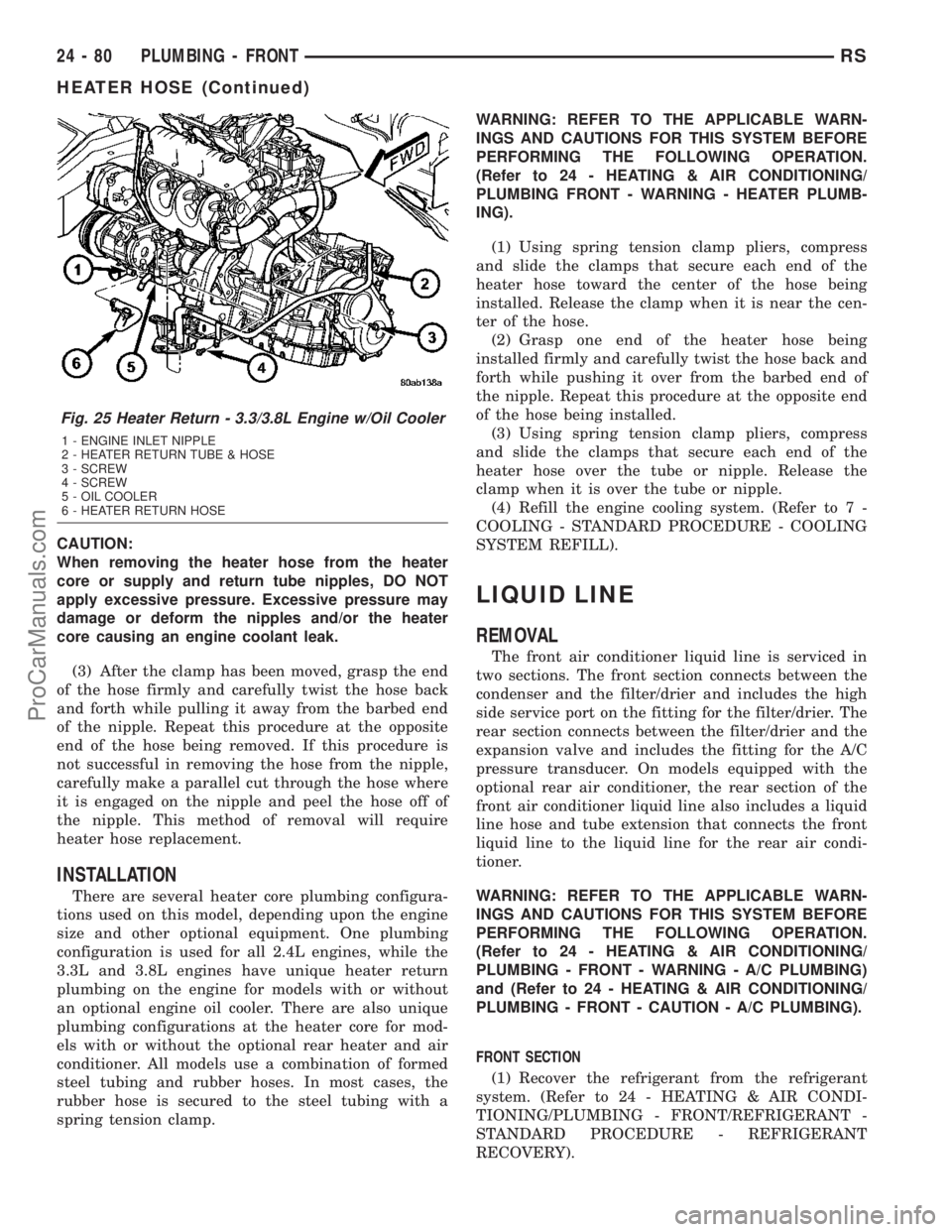
Fig. 25 Heater Return - 3.3/3.8L Engine w/Oil Cooler
1 - ENGINE INLET NIPPLE
2 - HEATER RETURN TUBE & HOSE
3 - SCREW
4 - SCREW
5 - OIL COOLER
6 - HEATER RETURN HOSE
24 - 80 PLUMBING - FRONTRS
HEATER HOSE (Continued)
ProCarManuals.com
Page 2095 of 2177
INSTALLATION
(1) Remove the tape or plugs from the evaporator
tube fittings and both expansion valve ports.
(2) Lubricate new rubber O-ring seals with clean
refrigerant oil and install them on the evaporator
tube fittings.
(3) Position the expansion valve onto the evapora-
tor tubes.
(4) Install and tighten the two screws that secure
the expansion valve to the evaporator tube sealing
plate. Tighten the screws to 11 N´m (97 in. lbs.).
(5) Reinstall the rear evaporator line extension
onto the expansion valve. (Refer to 24 - HEATING &
AIR CONDITIONING/PLUMBING - REAR/EVAPO-
RATOR - INSTALLATION - EVAPORATOR LINE
EXTENSION).
(6) Install the foam insulator wrap over the rear
expansion valve.
(7) Reinstall the rear heater-A/C unit housing into
the vehicle. (Refer to 24 - HEATING & AIR CONDI-
TIONING/DISTRIBUTION - REAR/REAR HEATER-
A/C HOUSING - INSTALLATION).
(8) Run the HVAC Cooldown Test to verify proper
operation.
HEATER CORE
DESCRIPTION
The rear heater core is located near the front of
the rear heater-A/C unit housing, behind the right
rear wheel house. It is a heat exchanger made of
rows of tubes and fins. One end of the core is fitted
with a molded plastic tank that includes integral
heater core inlet and outlet nipples. The heater core
can be serviced without removing the rear heater-A/C
unit housing from the vehicle. The heater core cannot
be repaired and, if faulty or damaged, it must be
replaced.
OPERATION
Engine coolant is circulated through heater hoses
to the heater core at all times. As the coolant flows
through the heater core, heat removed from the
engine is transferred to the heater core fins and
tubes. Air directed through the heater core picks up
the heat from the heater core fins. The blend air door
allows control of the heater output air temperature
by controlling how much of the air flowing through
the rear heater-A/C unit housing is directed through
the heater core.
STANDARD PROCEDURE - HEATER CORE
FILLING
In its final installed position, the rear heater core
is positioned higher than the radiator fill cap. There-fore, when the cooling system is drained and refilled,
gravity will not refill the heater core with coolant to
the proper level. This may result in two problems:1.
Insufficient coolant level in the engine cooling sys-
tem, which may result in engine overheating.2.Air
entrapped within the rear heater core, which may
result in insufficient rear heater performance. There
are two methods that may be employed to prevent
these problems:1.Pre-filling of the rear heater core.
2.Thermal cycling of the engine cooling system. Fol-
lowing are descriptions of both prevention methods,
as well as a method to verify rear heater perfor-
mance.
WARNING: REFER TO THE APPLICABLE WARN-
INGS AND CAUTIONS FOR THIS SYSTEM BEFORE
PERFORMING THE FOLLOWING OPERATION.
(Refer to 24 - HEATING & AIR CONDITIONING/
PLUMBING FRONT - WARNING - HEATER PLUMB-
ING).
PRE-FILLING
If the rear heater core or the rear heater-A/C hous-
ing have been removed from the vehicle for service,
the rear heater core may be pre-filled with the proper
engine coolant mixture prior to reconnecting the
heater hoses to the heater core hose fittings.
(1) The heater core should be installed in the rear
heater-A/C unit housing, and the rear heater-A/C
unit housing should be installed in the vehicle.
(2) Take the proper precautions to protect the car-
peting below the rear heater core from spilled engine
coolant and have absorbent toweling readily avail-
able to mop up any spills.
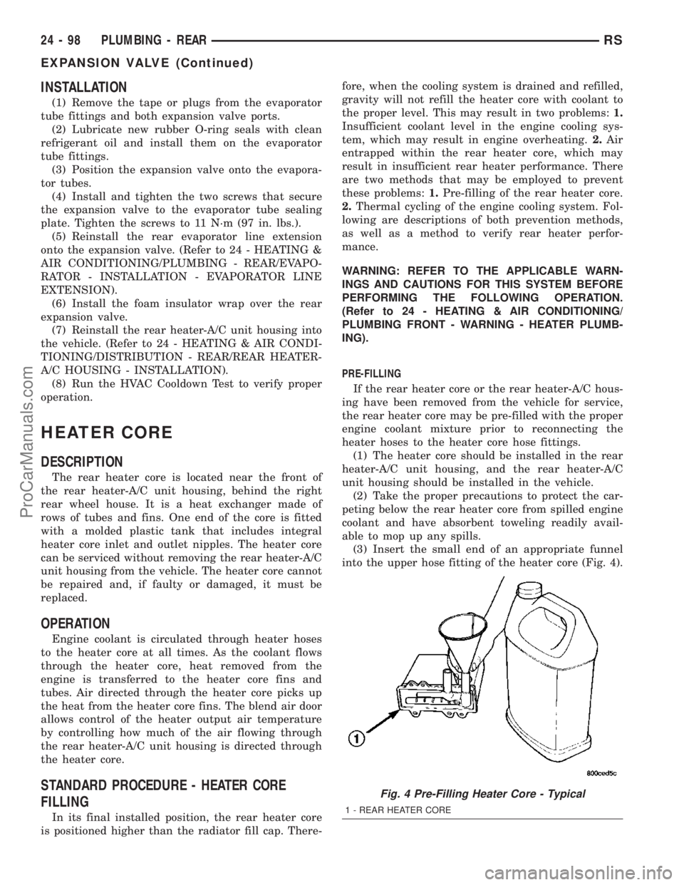
(3) Insert the small end of an appropriate funnel
into the upper hose fitting of the heater core (Fig. 4).
Fig. 4 Pre-Filling Heater Core - Typical
1 - REAR HEATER CORE
24 - 98 PLUMBING - REARRS
EXPANSION VALVE (Continued)
ProCarManuals.com
Page 2096 of 2177
(4) Carefully pour the proper pre-mixed engine
coolant solution into the rear heater core through a
funnel until coolant begins to appear at the lower
hose fitting of the heater core.
(5) Use absorbent toweling to clean up any engine
coolant spills from the preceding operation.
(6) Reconnect the heater hoses to the rear heater
core. (Refer to 24 - HEATING & AIR CONDITION-
ING/PLUMBING - REAR/HEATER HOSE - INSTAL-
LATION).
(7) Refill the engine cooling system. (Refer to 7 -
COOLING - STANDARD PROCEDURE - COOLING
SYSTEM REFILL).
THERMAL CYCLING
If the rear heater core was emptied and was not
pre-filled, it will be necessary to thermal cycle the
vehicle at least two times to ensure that the rear
heater core is properly filled.
(1) Refill the engine cooling system. (Refer to 7 -
COOLING - STANDARD PROCEDURE - COOLING
SYSTEM REFILL).
(2) Start the engine and allow it to operate until
the thermostat opens.
(3) Turn the engine off and allow it to cool.
(4) With the engine cold and not running, check
and top off the engine coolant level as necessary.
(Refer to 7 - COOLING - STANDARD PROCEDURE
- COOLANT LEVEL CHECK) and (Refer to 7 -
COOLING - STANDARD PROCEDURE - COOLANT
- ADDING).
(5) Start the engine and allow it to operate until
the thermostat opens again.
(6) Turn the engine off and allow it to cool down
again.
(7) With the engine cold and not running, check
and top off the engine coolant level as necessary.
(Refer to 7 - COOLING - STANDARD PROCEDURE
- COOLANT LEVEL CHECK) and (Refer to 7 -
COOLING - STANDARD PROCEDURE - COOLANT
- ADDING).
(8) Check the performance of the rear heater.
Refer to REAR HEATER PERFORMANCE CHECK .
REAR HEATER PERFORMANCE CHECK
Successful completion of the rear heater perfor-
mance check will confirm that the rear heater core is
properly filled with engine coolant. If the check is not
successful, either there is still air trapped in the rear
heater core or the rear heater plumbing is restricted.
This check should be performed with the vehicle in a
shop where the ambient temperature is about 21É C
(70É F).
(1) Start the engine and allow it to idle until it
warms up to normal operating temperature.(2) Adjust the heater-A/C controls so that the front
heater is turned Off, the rear heater is set for full
Heat, and the rear blower motor is at its highest
speed setting.
(3) Use an accurate test thermometer to measure
the temperature of the air being discharged from the
rear heater outlet located at the base of the right
C-pillar.
(4) Proper discharge air temperature readings
should be from 57É to 63É C (135É to 145É F).
REMOVAL
WARNING: REFER TO THE APPLICABLE WARN-
INGS AND CAUTIONS FOR THIS SYSTEM BEFORE
PERFORMING THE FOLLOWING OPERATION.
(Refer to 24 - HEATING & AIR CONDITIONING/
PLUMBING FRONT - WARNING - HEATER PLUMB-
ING).
(1) Drain the engine cooling system. (Refer to 7 -
COOLING - STANDARD PROCEDURE - COOLING
SYSTEM DRAIN).
(2) Remove the right quarter trim panel and right
D-pillar trim panel from the quarter inner panel.
(Refer to 23 - BODY/INTERIOR/QUARTER TRIM
PANEL - REMOVAL).
(3) Remove the rear heater distribution duct from
the right quarter inner panel. (Refer to 24 - HEAT-
ING & AIR CONDITIONING/DISTRIBUTION -
REAR/REAR HEATER DISTRIBUTION DUCT -
REMOVAL).
(4) Remove the screw that secures the back of the
rear heater-A/C unit housing to the right D-pillar.
(5) Remove the screw that secures the front of the
rear heater-A/C unit housing to the right quarter
inner panel.
(6) Take the proper precautions to protect the car-
peting below the rear heater core from spilled engine
coolant and have absorbent toweling readily avail-
able to mop up any spills.
(7) Disconnect the heater hoses at the rear heater
core. (Refer to 24 - HEATING & AIR CONDITION-
ING/PLUMBING - REAR/HEATER HOSE - REMOV-
AL).
(8) Install plugs in, or tape over the opened heater
core fittings and both heater hoses (Fig. 5).
(9) Use absorbent toweling to clean up any engine
coolant spills from the preceding operation.
(10) Release the four latch tabs that secure the
heater core in the rear heater-A/C unit housing.
(11) Carefully pull the heater core straight out of
the rear heater-A/C unit housing.
(12) Use absorbent toweling to clean up any
engine coolant spills from the preceding operation.
RSPLUMBING - REAR24-99
HEATER CORE (Continued)
ProCarManuals.com