Page 1499 of 2177

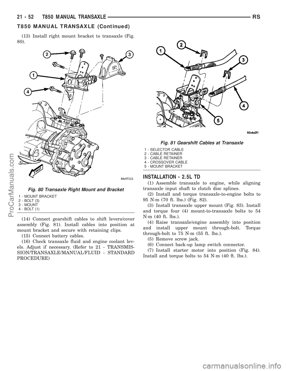
(13) Install right mount bracket to transaxle (Fig.
80).
(14) Connect gearshift cables to shift levers/cover
assembly (Fig. 81). Install cables into position at
mount bracket and secure with retaining clips.
(15) Connect battery cables.
(16) Check transaxle fluid and engine coolant lev-
els. Adjust if necessary. (Refer to 21 - TRANSMIS-
SION/TRANSAXLE/MANUAL/FLUID - STANDARD
PROCEDURE)
INSTALLATION - 2.5L TD
(1) Assemble transaxle to engine, while aligning
transaxle input shaft to clutch disc splines.
(2) Install and torque transaxle-to-engine bolts to
95 N´m (70 ft. lbs.) (Fig. 82).
(3) Install transaxle upper mount (Fig. 83). Install
and torque four (4) mount-to-transaxle bolts to 54
N´m (40 ft. lbs.).
(4) Raise transaxle/engine assembly into position
and install upper mount through-bolt. Torque
through-bolt to 75 N´m (55 ft. lbs.).
(5) Remove screw jack.
(6) Connect back-up lamp switch connector.
(7) Install starter motor into position (Fig. 84).
Install and torque bolts to 54 N´m (40 ft. lbs.).
Fig. 80 Transaxle Right Mount and Bracket
1 - MOUNT BRACKET
2 - BOLT (3)
3 - MOUNT
4 - BOLT (1)
Fig. 81 Gearshift Cables at Transaxle
1 - SELECTOR CABLE
2 - CABLE RETAINER
3 - CABLE RETAINER
4 - CROSSOVER CABLE
5 - MOUNT BRACKET
21 - 52 T850 MANUAL TRANSAXLERS
T850 MANUAL TRANSAXLE (Continued)
ProCarManuals.com
Page 1502 of 2177
(15) Install coolant recovery bottle bracket (Fig.
88).
(16) Install coolant recovery bottle to bracket.
(17) Connect battery temperature sensor and
install battery tray (Fig. 89).(18) Install battery, hold-down clamp and nut (Fig.
90).
(19) Install battery thermal shield and clutch cable
eyelet (Fig. 91).
(20) Connect battery cables.
(21) Check transaxle fluid and engine coolant lev-
els. Adjust if necessary. (Refer to 21 - TRANSMIS-
SION/TRANSAXLE/MANUAL/FLUID - STANDARD
PROCEDURE)
Fig. 88 Coolant Recovery Bottle Bracket
1 - COOLANT RECOVERY BOTTLE BRACKET
2 - NUT
3 - MOUNT BRACKET
Fig. 89 Battery Tray
1 - BATTERY TRAY
Fig. 90 Battery and Hold-Down Clamp
1 - BATTERY
2 - HOLD-DOWN CLAMP
Fig. 91 Battery Thermal Shield
1 - BATTERY THERMAL SHIELD
RST850 MANUAL TRANSAXLE21-55
T850 MANUAL TRANSAXLE (Continued)
ProCarManuals.com
Page 1522 of 2177
(10)2.4L Gas equipped models goto Step 15.
2.5L TD models:Remove battery thermal shield
(Fig. 138).
(11) Remove battery hold down nut, clamp, and
battery (Fig. 139).(12) Remove battery tray (Fig. 140). Disconnect
battery temperature sensor.
(13) Remove coolant recovery bottle from bracket.
(14) Remove coolant recovery bottle mounting
bracket (Fig. 141).
Fig. 138 Battery Thermal Shield
1 - BATTERY THERMAL SHIELD
Fig. 139 Battery and Hold-Down Clamp
1 - BATTERY
2 - HOLD-DOWN CLAMP
Fig. 140 Battery Tray
1 - BATTERY TRAY
Fig. 141 Coolant Recovery Bottle Bracket
1 - COOLANT RECOVERY BOTTLE BRACKET
2 - NUT
3 - MOUNT BRACKET
RST850 MANUAL TRANSAXLE21-75
GEARSHIFT CABLE - CROSSOVER (Continued)
ProCarManuals.com
Page 1523 of 2177

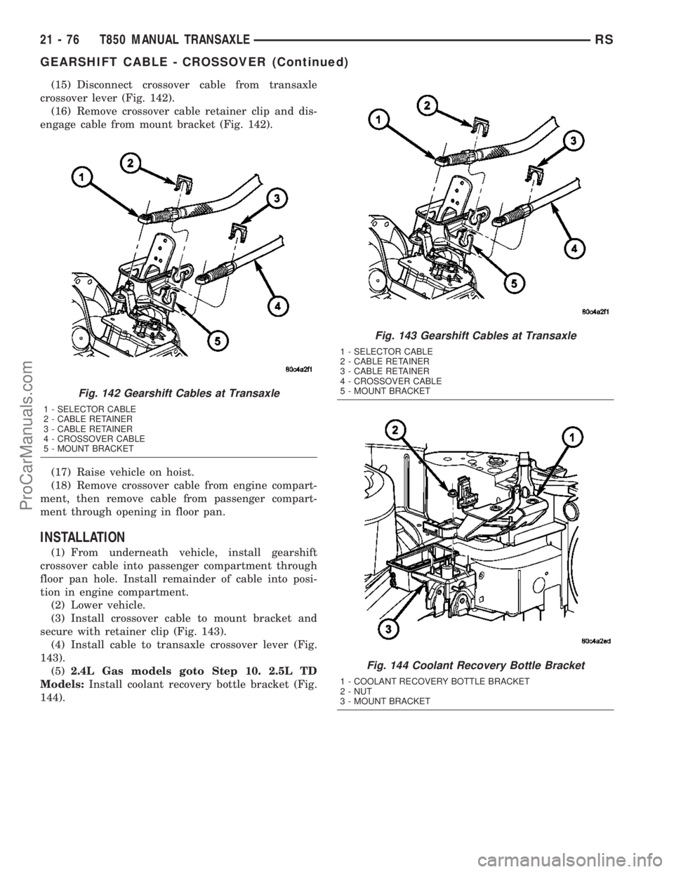
(15) Disconnect crossover cable from transaxle
crossover lever (Fig. 142).
(16) Remove crossover cable retainer clip and dis-
engage cable from mount bracket (Fig. 142).
(17) Raise vehicle on hoist.
(18) Remove crossover cable from engine compart-
ment, then remove cable from passenger compart-
ment through opening in floor pan.
INSTALLATION
(1) From underneath vehicle, install gearshift
crossover cable into passenger compartment through
floor pan hole. Install remainder of cable into posi-
tion in engine compartment.
(2) Lower vehicle.
(3) Install crossover cable to mount bracket and
secure with retainer clip (Fig. 143).
(4) Install cable to transaxle crossover lever (Fig.
143).
(5)2.4L Gas models goto Step 10. 2.5L TD
Models:Install coolant recovery bottle bracket (Fig.
144).
Fig. 142 Gearshift Cables at Transaxle
1 - SELECTOR CABLE
2 - CABLE RETAINER
3 - CABLE RETAINER
4 - CROSSOVER CABLE
5 - MOUNT BRACKET
Fig. 143 Gearshift Cables at Transaxle
1 - SELECTOR CABLE
2 - CABLE RETAINER
3 - CABLE RETAINER
4 - CROSSOVER CABLE
5 - MOUNT BRACKET
Fig. 144 Coolant Recovery Bottle Bracket
1 - COOLANT RECOVERY BOTTLE BRACKET
2 - NUT
3 - MOUNT BRACKET
21 - 76 T850 MANUAL TRANSAXLERS
GEARSHIFT CABLE - CROSSOVER (Continued)
ProCarManuals.com
Page 1524 of 2177
(6) Install coolant recovery bottle to bracket.
(7) Connect battery temperature sensor to battery
tray. Install battery tray into position (Fig. 145).
(8) Install battery, hold-down clamp, and nut (Fig.
146).(9) Install battery thermal shield (Fig. 147).
(10) Install crossover cable to gearshift mechanism
(Fig. 148). Install retainer clip (Fig. 149).
Fig. 145 Battery Tray
1 - BATTERY TRAY
Fig. 146 Battery and Hold-Down Clamp
1 - BATTERY
2 - HOLD-DOWN CLAMP
Fig. 147 Battery Thermal Shield
1 - BATTERY THERMAL SHIELD
Fig. 148 Crossover Cable at Gearshift Mechanism
1 - GEARSHIFT MECHANISM
2 - CROSSOVER CABLE
RST850 MANUAL TRANSAXLE21-77
GEARSHIFT CABLE - CROSSOVER (Continued)
ProCarManuals.com
Page 1530 of 2177
(11) Remove battery hold down nut, clamp, and
battery (Fig. 168).
(12) Remove battery tray (Fig. 169). Disconnect
battery temperature sensor.(13) Remove coolant recovery bottle from bracket.
(14) Remove coolant recovery bottle mounting
bracket (Fig. 170).
(15) Disconnect crossover cable from transaxle
crossover lever (Fig. 171).
(16) Remove crossover cable retainer clip and dis-
engage cable from mount bracket (Fig. 171).
Fig. 168 Battery and Hold-Down Clamp
1 - BATTERY
2 - HOLD-DOWN CLAMP
Fig. 169 Battery Tray
1 - BATTERY TRAY
Fig. 170 Coolant Recovery Bottle Bracket
1 - COOLANT RECOVERY BOTTLE BRACKET
2 - NUT
3 - MOUNT BRACKET
Fig. 171 Gearshift Cables at Transaxle
1 - SELECTOR CABLE
2 - CABLE RETAINER
3 - CABLE RETAINER
4 - CROSSOVER CABLE
5 - MOUNT BRACKET
RST850 MANUAL TRANSAXLE21-83
GEARSHIFT CABLE - SELECTOR (Continued)
ProCarManuals.com
Page 1531 of 2177

(17) Raise vehicle on hoist.
(18) Remove selector cable from engine compart-
ment, then remove cable from passenger compart-
ment through opening in floor pan.
INSTALLATION
(1) From underneath vehicle, install gearshift
selector cable into passenger compartment through
floor pan hole. Install remainder of cable into posi-
tion in engine compartment.
(2) Lower vehicle.
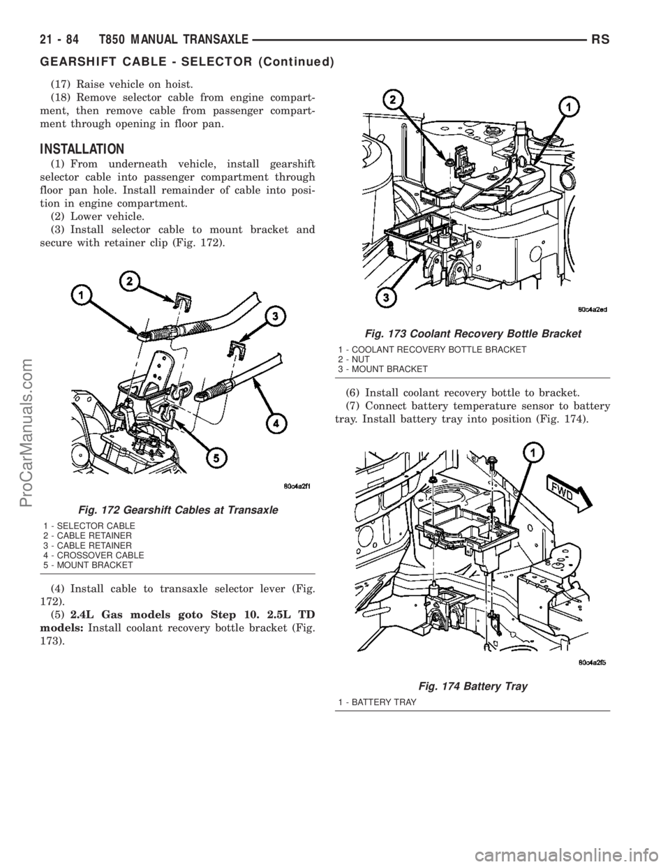
(3) Install selector cable to mount bracket and
secure with retainer clip (Fig. 172).
(4) Install cable to transaxle selector lever (Fig.
172).
(5)2.4L Gas models goto Step 10. 2.5L TD
models:Install coolant recovery bottle bracket (Fig.
173).(6) Install coolant recovery bottle to bracket.
(7) Connect battery temperature sensor to battery
tray. Install battery tray into position (Fig. 174).
Fig. 172 Gearshift Cables at Transaxle
1 - SELECTOR CABLE
2 - CABLE RETAINER
3 - CABLE RETAINER
4 - CROSSOVER CABLE
5 - MOUNT BRACKET
Fig. 173 Coolant Recovery Bottle Bracket
1 - COOLANT RECOVERY BOTTLE BRACKET
2 - NUT
3 - MOUNT BRACKET
Fig. 174 Battery Tray
1 - BATTERY TRAY
21 - 84 T850 MANUAL TRANSAXLERS
GEARSHIFT CABLE - SELECTOR (Continued)
ProCarManuals.com
Page 1571 of 2177

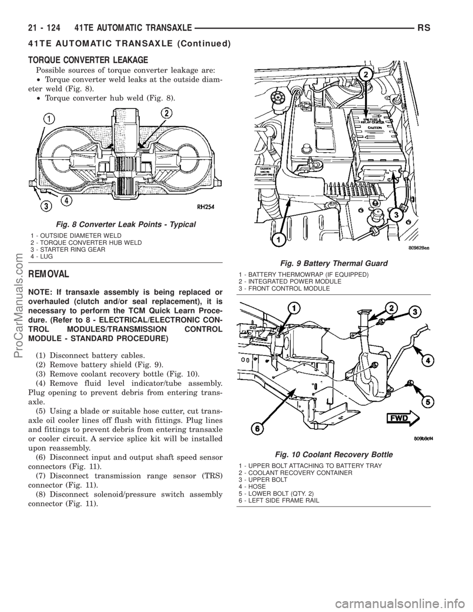
TORQUE CONVERTER LEAKAGE
Possible sources of torque converter leakage are:
²Torque converter weld leaks at the outside diam-
eter weld (Fig. 8).
²Torque converter hub weld (Fig. 8).
REMOVAL
NOTE: If transaxle assembly is being replaced or
overhauled (clutch and/or seal replacement), it is
necessary to perform the TCM Quick Learn Proce-
dure. (Refer to 8 - ELECTRICAL/ELECTRONIC CON-
TROL MODULES/TRANSMISSION CONTROL
MODULE - STANDARD PROCEDURE)
(1) Disconnect battery cables.
(2) Remove battery shield (Fig. 9).
(3) Remove coolant recovery bottle (Fig. 10).
(4) Remove fluid level indicator/tube assembly.
Plug opening to prevent debris from entering trans-
axle.
(5) Using a blade or suitable hose cutter, cut trans-
axle oil cooler lines off flush with fittings. Plug lines
and fittings to prevent debris from entering transaxle
or cooler circuit. A service splice kit will be installed
upon reassembly.
(6) Disconnect input and output shaft speed sensor
connectors (Fig. 11).
(7) Disconnect transmission range sensor (TRS)
connector (Fig. 11).
(8) Disconnect solenoid/pressure switch assembly
connector (Fig. 11).
Fig. 8 Converter Leak Points - Typical
1 - OUTSIDE DIAMETER WELD
2 - TORQUE CONVERTER HUB WELD
3 - STARTER RING GEAR
4 - LUG
Fig. 9 Battery Thermal Guard
1 - BATTERY THERMOWRAP (IF EQUIPPED)
2 - INTEGRATED POWER MODULE
3 - FRONT CONTROL MODULE
Fig. 10 Coolant Recovery Bottle
1 - UPPER BOLT ATTACHING TO BATTERY TRAY
2 - COOLANT RECOVERY CONTAINER
3 - UPPER BOLT
4 - HOSE
5 - LOWER BOLT (QTY. 2)
6 - LEFT SIDE FRAME RAIL
21 - 124 41TE AUTOMATIC TRANSAXLERS
41TE AUTOMATIC TRANSAXLE (Continued)
ProCarManuals.com