2003 CHRYSLER CARAVAN engine oil
[x] Cancel search: engine oilPage 1193 of 2177
(18) Remove axle shafts. (Refer to 3 - DIFFEREN-
TIAL & DRIVELINE/HALF SHAFT - REMOVAL)
(19) Drain engine oil and remove oil filter. (Refer
to 9 - ENGINE/LUBRICATION/OIL - STANDARD
PROCEDURE)
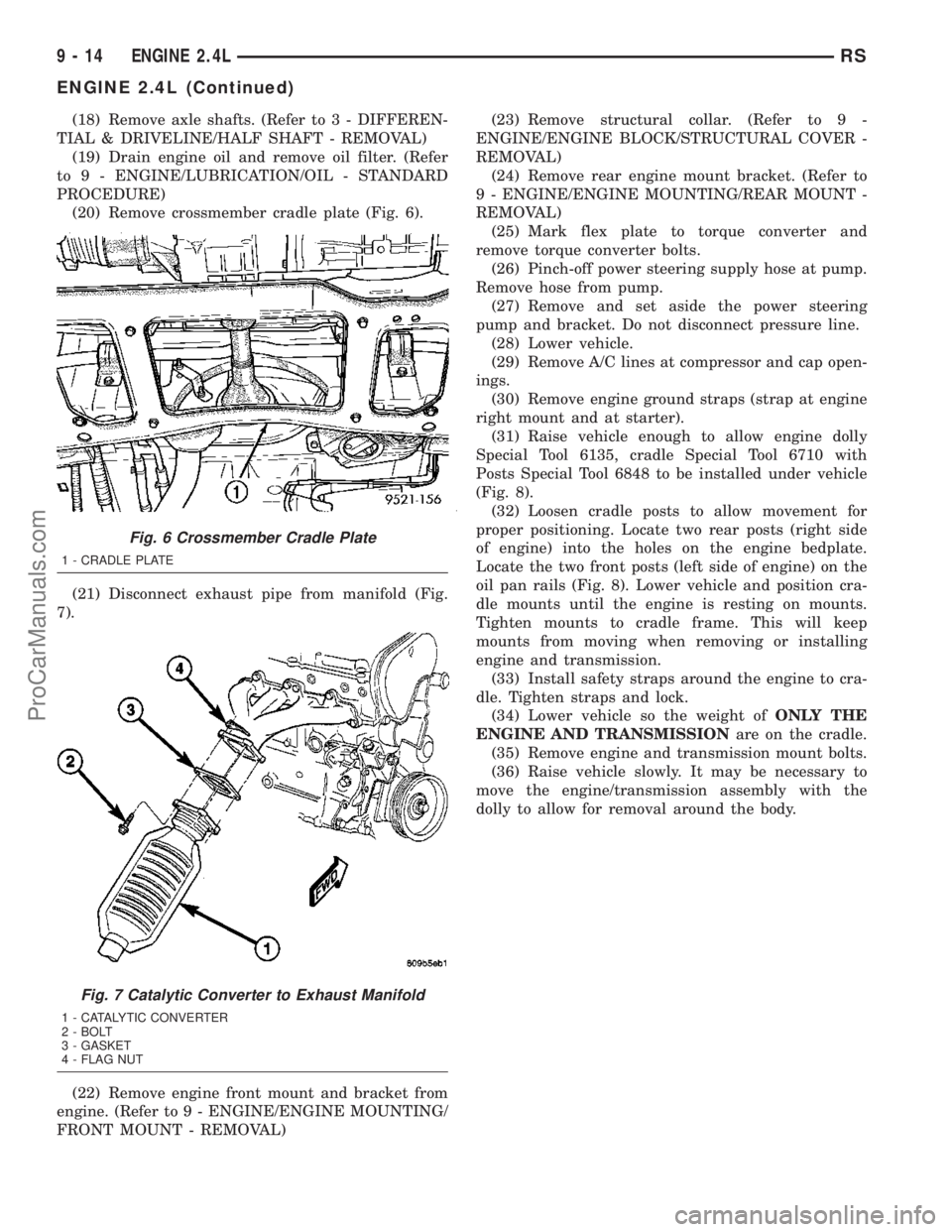
(20) Remove crossmember cradle plate (Fig. 6).
(21) Disconnect exhaust pipe from manifold (Fig.
7).
(22) Remove engine front mount and bracket from
engine. (Refer to 9 - ENGINE/ENGINE MOUNTING/
FRONT MOUNT - REMOVAL)(23) Remove structural collar. (Refer to 9 -
ENGINE/ENGINE BLOCK/STRUCTURAL COVER -
REMOVAL)
(24) Remove rear engine mount bracket. (Refer to
9 - ENGINE/ENGINE MOUNTING/REAR MOUNT -
REMOVAL)
(25) Mark flex plate to torque converter and
remove torque converter bolts.
(26) Pinch-off power steering supply hose at pump.
Remove hose from pump.
(27) Remove and set aside the power steering
pump and bracket. Do not disconnect pressure line.
(28) Lower vehicle.
(29) Remove A/C lines at compressor and cap open-
ings.
(30) Remove engine ground straps (strap at engine
right mount and at starter).
(31) Raise vehicle enough to allow engine dolly
Special Tool 6135, cradle Special Tool 6710 with
Posts Special Tool 6848 to be installed under vehicle
(Fig. 8).
(32) Loosen cradle posts to allow movement for
proper positioning. Locate two rear posts (right side
of engine) into the holes on the engine bedplate.
Locate the two front posts (left side of engine) on the
oil pan rails (Fig. 8). Lower vehicle and position cra-
dle mounts until the engine is resting on mounts.
Tighten mounts to cradle frame. This will keep
mounts from moving when removing or installing
engine and transmission.
(33) Install safety straps around the engine to cra-
dle. Tighten straps and lock.
(34) Lower vehicle so the weight ofONLY THE
ENGINE AND TRANSMISSIONare on the cradle.
(35) Remove engine and transmission mount bolts.
(36) Raise vehicle slowly. It may be necessary to
move the engine/transmission assembly with the
dolly to allow for removal around the body.
Fig. 6 Crossmember Cradle Plate
1 - CRADLE PLATE
Fig. 7 Catalytic Converter to Exhaust Manifold
1 - CATALYTIC CONVERTER
2 - BOLT
3 - GASKET
4 - FLAG NUT
9 - 14 ENGINE 2.4LRS
ENGINE 2.4L (Continued)
ProCarManuals.com
Page 1195 of 2177
INSTALLATION - ENGINE ASSEMBLY
(1) Position engine and transmission assembly
under vehicle and slowly lower the vehicle over the
engine and transmission.
(2) Align engine and transmission mounts to
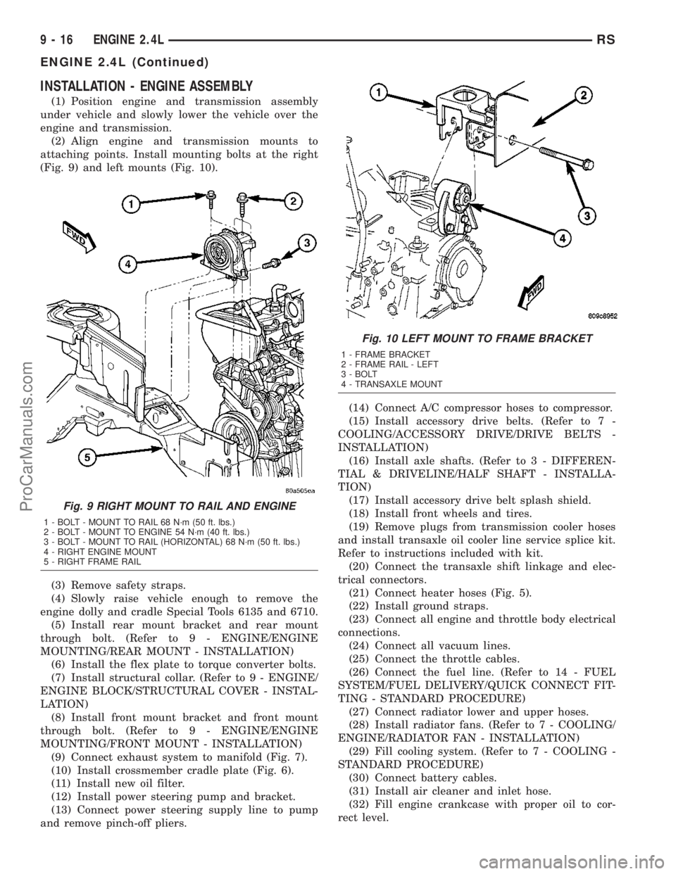
attaching points. Install mounting bolts at the right
(Fig. 9) and left mounts (Fig. 10).
(3) Remove safety straps.
(4) Slowly raise vehicle enough to remove the
engine dolly and cradle Special Tools 6135 and 6710.
(5) Install rear mount bracket and rear mount
through bolt. (Refer to 9 - ENGINE/ENGINE
MOUNTING/REAR MOUNT - INSTALLATION)
(6) Install the flex plate to torque converter bolts.
(7) Install structural collar. (Refer to 9 - ENGINE/
ENGINE BLOCK/STRUCTURAL COVER - INSTAL-
LATION)
(8) Install front mount bracket and front mount
through bolt. (Refer to 9 - ENGINE/ENGINE
MOUNTING/FRONT MOUNT - INSTALLATION)
(9) Connect exhaust system to manifold (Fig. 7).
(10) Install crossmember cradle plate (Fig. 6).
(11) Install new oil filter.
(12) Install power steering pump and bracket.
(13) Connect power steering supply line to pump
and remove pinch-off pliers.(14) Connect A/C compressor hoses to compressor.
(15) Install accessory drive belts. (Refer to 7 -
COOLING/ACCESSORY DRIVE/DRIVE BELTS -
INSTALLATION)
(16) Install axle shafts. (Refer to 3 - DIFFEREN-
TIAL & DRIVELINE/HALF SHAFT - INSTALLA-
TION)
(17) Install accessory drive belt splash shield.
(18) Install front wheels and tires.
(19) Remove plugs from transmission cooler hoses
and install transaxle oil cooler line service splice kit.
Refer to instructions included with kit.
(20) Connect the transaxle shift linkage and elec-
trical connectors.
(21) Connect heater hoses (Fig. 5).
(22) Install ground straps.
(23) Connect all engine and throttle body electrical
connections.
(24) Connect all vacuum lines.
(25) Connect the throttle cables.
(26) Connect the fuel line. (Refer to 14 - FUEL
SYSTEM/FUEL DELIVERY/QUICK CONNECT FIT-
TING - STANDARD PROCEDURE)
(27) Connect radiator lower and upper hoses.
(28) Install radiator fans. (Refer to 7 - COOLING/
ENGINE/RADIATOR FAN - INSTALLATION)
(29) Fill cooling system. (Refer to 7 - COOLING -
STANDARD PROCEDURE)
(30) Connect battery cables.
(31) Install air cleaner and inlet hose.
(32) Fill engine crankcase with proper oil to cor-
rect level.
Fig. 9 RIGHT MOUNT TO RAIL AND ENGINE
1 - BOLT - MOUNT TO RAIL 68 N´m (50 ft. lbs.)
2 - BOLT - MOUNT TO ENGINE 54 N´m (40 ft. lbs.)
3 - BOLT - MOUNT TO RAIL (HORIZONTAL) 68 N´m (50 ft. lbs.)
4 - RIGHT ENGINE MOUNT
5 - RIGHT FRAME RAIL
Fig. 10 LEFT MOUNT TO FRAME BRACKET
1 - FRAME BRACKET
2 - FRAME RAIL - LEFT
3 - BOLT
4 - TRANSAXLE MOUNT
9 - 16 ENGINE 2.4LRS
ENGINE 2.4L (Continued)
ProCarManuals.com
Page 1196 of 2177
(33) Start engine and run until operating temper-
ature is reached.
(34) Adjust transmission linkage, if necessary.
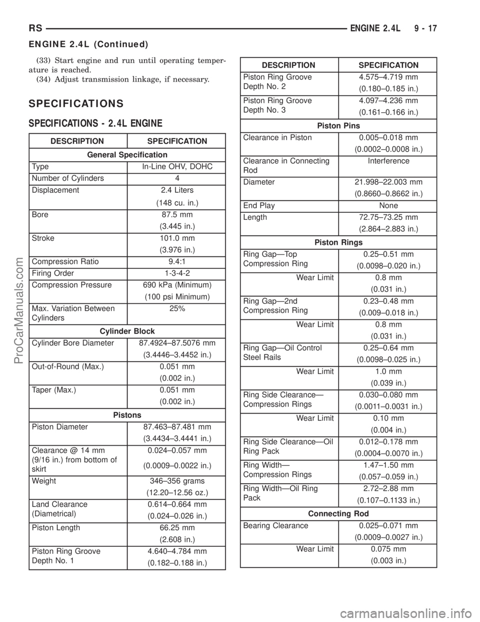
SPECIFICATIONS
SPECIFICATIONS - 2.4L ENGINE
DESCRIPTION SPECIFICATION
General Specification
Type In-Line OHV, DOHC
Number of Cylinders 4
Displacement 2.4 Liters
(148 cu. in.)
Bore 87.5 mm
(3.445 in.)
Stroke 101.0 mm
(3.976 in.)
Compression Ratio 9.4:1
Firing Order 1-3-4-2
Compression Pressure 690 kPa (Minimum)
(100 psi Minimum)
Max. Variation Between
Cylinders25%
Cylinder Block
Cylinder Bore Diameter 87.4924±87.5076 mm
(3.4446±3.4452 in.)
Out-of-Round (Max.) 0.051 mm
(0.002 in.)
Taper (Max.) 0.051 mm
(0.002 in.)
Pistons
Piston Diameter 87.463±87.481 mm
(3.4434±3.4441 in.)
Clearance @ 14 mm
(9/16 in.) from bottom of
skirt0.024±0.057 mm
(0.0009±0.0022 in.)
Weight 346±356 grams
(12.20±12.56 oz.)
Land Clearance
(Diametrical)0.614±0.664 mm
(0.024±0.026 in.)
Piston Length 66.25 mm
(2.608 in.)
Piston Ring Groove
Depth No. 14.640±4.784 mm
(0.182±0.188 in.)
DESCRIPTION SPECIFICATION
Piston Ring Groove
Depth No. 24.575±4.719 mm
(0.180±0.185 in.)
Piston Ring Groove
Depth No. 34.097±4.236 mm
(0.161±0.166 in.)
Piston Pins
Clearance in Piston 0.005±0.018 mm
(0.0002±0.0008 in.)
Clearance in Connecting
RodInterference
Diameter 21.998±22.003 mm
(0.8660±0.8662 in.)
End Play None
Length 72.75±73.25 mm
(2.864±2.883 in.)
Piston Rings
Ring GapÐTop
Compression Ring0.25±0.51 mm
(0.0098±0.020 in.)
Wear Limit 0.8 mm
(0.031 in.)
Ring GapÐ2nd
Compression Ring0.23±0.48 mm
(0.009±0.018 in.)
Wear Limit 0.8 mm
(0.031 in.)
Ring GapÐOil Control
Steel Rails0.25±0.64 mm
(0.0098±0.025 in.)
Wear Limit 1.0 mm
(0.039 in.)
Ring Side ClearanceÐ
Compression Rings0.030±0.080 mm
(0.0011±0.0031 in.)
Wear Limit 0.10 mm
(0.004 in.)
Ring Side ClearanceÐOil
Ring Pack0.012±0.178 mm
(0.0004±0.0070 in.)
Ring WidthÐ
Compression Rings1.47±1.50 mm
(0.057±0.059 in.)
Ring WidthÐOil Ring
Pack2.72±2.88 mm
(0.107±0.1133 in.)
Connecting Rod
Bearing Clearance 0.025±0.071 mm
(0.0009±0.0027 in.)
Wear Limit 0.075 mm
(0.003 in.)
RSENGINE 2.4L9-17
ENGINE 2.4L (Continued)
ProCarManuals.com
Page 1198 of 2177
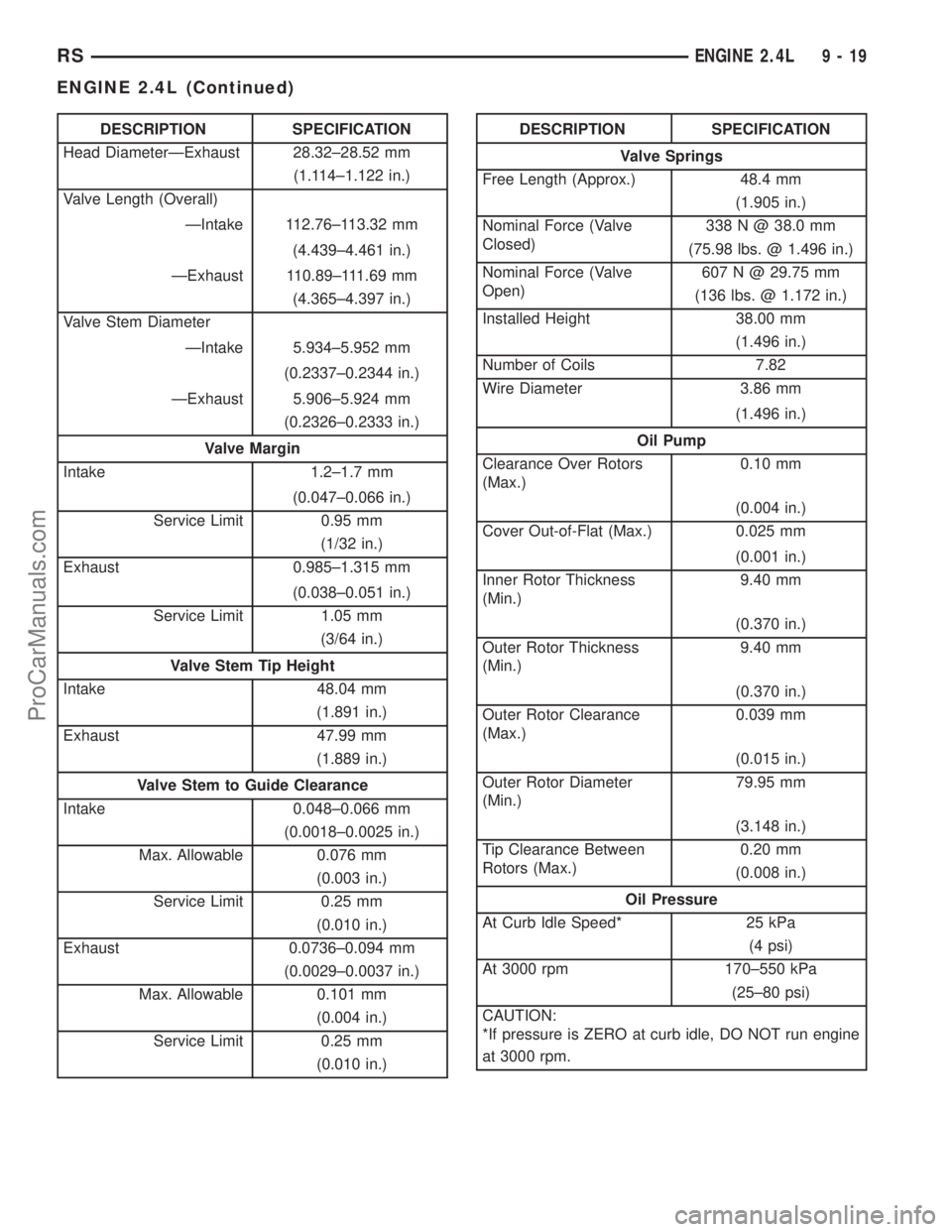
DESCRIPTION SPECIFICATION
Head DiameterÐExhaust 28.32±28.52 mm
(1.114±1.122 in.)
Valve Length (Overall)
ÐIntake 112.76±113.32 mm
(4.439±4.461 in.)
ÐExhaust 110.89±111.69 mm
(4.365±4.397 in.)
Valve Stem Diameter
ÐIntake 5.934±5.952 mm
(0.2337±0.2344 in.)
ÐExhaust 5.906±5.924 mm
(0.2326±0.2333 in.)
Valve Margin
Intake 1.2±1.7 mm
(0.047±0.066 in.)
Service Limit 0.95 mm
(1/32 in.)
Exhaust 0.985±1.315 mm
(0.038±0.051 in.)
Service Limit 1.05 mm
(3/64 in.)
Valve Stem Tip Height
Intake 48.04 mm
(1.891 in.)
Exhaust 47.99 mm
(1.889 in.)
Valve Stem to Guide Clearance
Intake 0.048±0.066 mm
(0.0018±0.0025 in.)
Max. Allowable 0.076 mm
(0.003 in.)
Service Limit 0.25 mm
(0.010 in.)
Exhaust 0.0736±0.094 mm
(0.0029±0.0037 in.)
Max. Allowable 0.101 mm
(0.004 in.)
Service Limit 0.25 mm
(0.010 in.)DESCRIPTION SPECIFICATION
Valve Springs
Free Length (Approx.) 48.4 mm
(1.905 in.)
Nominal Force (Valve
Closed)338 N @ 38.0 mm
(75.98 lbs. @ 1.496 in.)
Nominal Force (Valve
Open)607 N @ 29.75 mm
(136 lbs. @ 1.172 in.)
Installed Height 38.00 mm
(1.496 in.)
Number of Coils 7.82
Wire Diameter 3.86 mm
(1.496 in.)
Oil Pump
Clearance Over Rotors
(Max.)0.10 mm
(0.004 in.)
Cover Out-of-Flat (Max.) 0.025 mm
(0.001 in.)
Inner Rotor Thickness
(Min.)9.40 mm
(0.370 in.)
Outer Rotor Thickness
(Min.)9.40 mm
(0.370 in.)
Outer Rotor Clearance
(Max.)0.039 mm
(0.015 in.)
Outer Rotor Diameter
(Min.)79.95 mm
(3.148 in.)
Tip Clearance Between
Rotors (Max.)0.20 mm
(0.008 in.)
Oil Pressure
At Curb Idle Speed* 25 kPa
(4 psi)
At 3000 rpm 170±550 kPa
(25±80 psi)
CAUTION:
*If pressure is ZERO at curb idle, DO NOT run engine
at 3000 rpm.
RSENGINE 2.4L9-19
ENGINE 2.4L (Continued)
ProCarManuals.com
Page 1199 of 2177
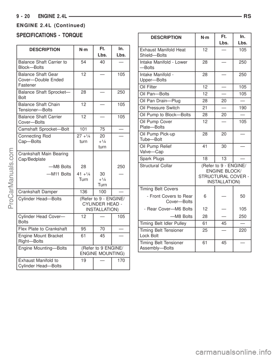
SPECIFICATIONS - TORQUE
DESCRIPTION N´mFt.
Lbs.In.
Lbs.
Balance Shaft Carrier to
BlockÐBolts54 40 Ð
Balance Shaft Gear
CoverÐDouble Ended
Fastener12 Ð 105
Balance Shaft SprocketÐ
Bolt28 Ð 250
Balance Shaft Chain
TensionerÐBolts12 Ð 105
Balance Shaft Carrier
CoverÐBolts12 Ð 105
Camshaft SprocketÐBolt 101 75 Ð
Connecting Rod
CapÐBolts27 +
1¤4
turn20
+1¤4
turnÐ
Crankshaft Main Bearing
Cap/Bedplate
ÐM8 Bolts 28 250
ÐM11 Bolts 41 +
1¤4
Turn30
+1¤4
TurnÐ
Crankshaft Damper 136 100 Ð
Cylinder HeadÐBolts (Refer to 9 - ENGINE/
CYLINDER HEAD -
INSTALLATION)
Cylinder Head CoverÐ
Bolts12 Ð 105
Flex Plate to Crankshaft 95 70 Ð
Engine Mount Bracket
RightÐBolts61 45 Ð
Engine MountingÐBolts (Refer to 9 ENGINE/
ENGINE MOUNTING)
Exhaust Manifold to
Cylinder HeadÐBolts19 Ð 170
DESCRIPTION N´mFt.
Lbs.In.
Lbs.
Exhaust Manifold Heat
ShieldÐBolts12 Ð 105
Intake Manifold - Lower
ÐBolts28 Ð 250
Intake Manifold -
UpperÐBolts28 Ð 250
Oil Filter 12 Ð 105
Oil PanÐBolts 12 Ð 105
Oil Pan DrainÐPlug 28 20 Ð
Oil Pressure Switch 21 Ð 190
Oil Pump to BlockÐBolts 28 20 Ð
Oil Pump Cover
PlateÐBolts12 Ð 105
Oil Pump Pick-up
TubeÐBolt28 20 Ð
Oil Pump Relief
ValveÐCap41 30 Ð
Spark Plugs 18 13 Ð
Structural Collar (Refer to 9 - ENGINE/
ENGINE BLOCK/
STRUCTURAL COVER -
INSTALLATION)
Timing Belt Covers
- Front Covers to Rear
CoverÐBolts6Ð50
- Rear CoverÐM6 Bolts 12 Ð 105
ÐM8 Bolts 28 Ð 250
Timing Belt Idler Pulley 61 45 Ð
Timing Belt Tensioner
Lock Bolt25 Ð 220
Timing Belt Tensioner
AssemblyÐBolts61 45 Ð
9 - 20 ENGINE 2.4LRS
ENGINE 2.4L (Continued)
ProCarManuals.com
Page 1201 of 2177
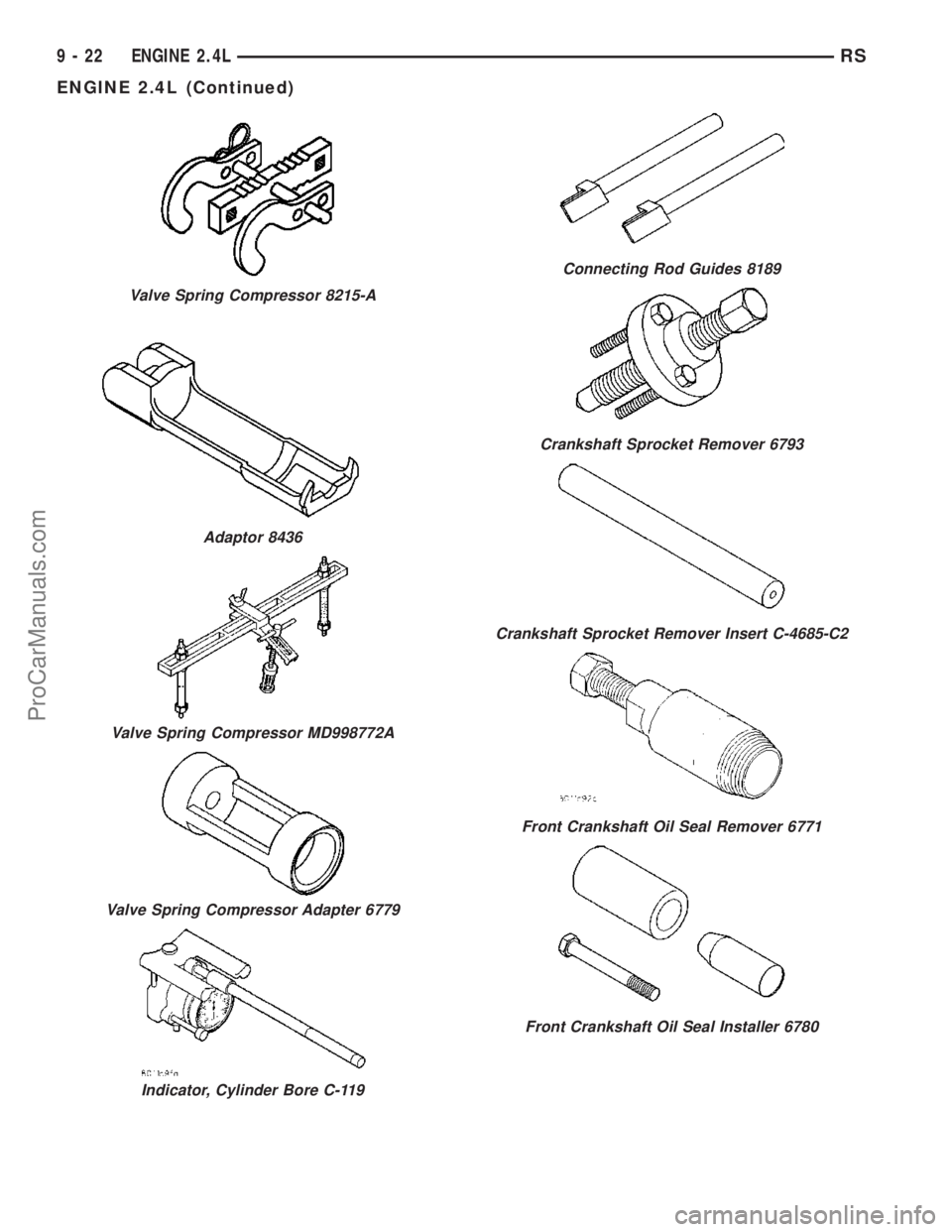
Valve Spring Compressor 8215-A
Adaptor 8436
Valve Spring Compressor MD998772A
Valve Spring Compressor Adapter 6779
Indicator, Cylinder Bore C-119
Connecting Rod Guides 8189
Crankshaft Sprocket Remover 6793
Crankshaft Sprocket Remover Insert C-4685-C2
Front Crankshaft Oil Seal Remover 6771
Front Crankshaft Oil Seal Installer 6780
9 - 22 ENGINE 2.4LRS
ENGINE 2.4L (Continued)
ProCarManuals.com
Page 1202 of 2177
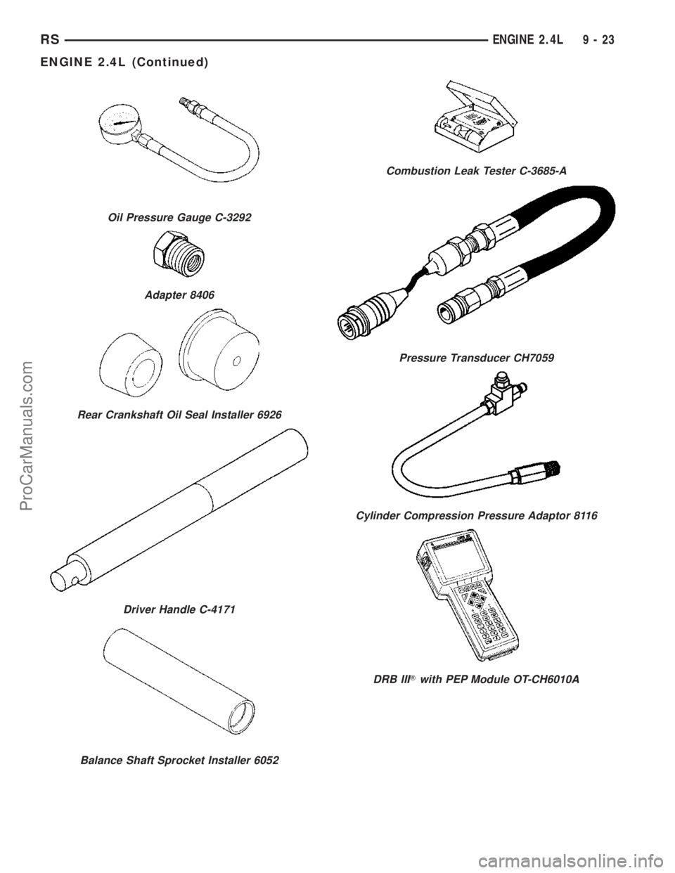
Oil Pressure Gauge C-3292
Adapter 8406
Rear Crankshaft Oil Seal Installer 6926
Driver Handle C-4171
Balance Shaft Sprocket Installer 6052
Combustion Leak Tester C-3685-A
Pressure Transducer CH7059
Cylinder Compression Pressure Adaptor 8116
DRB IIITwith PEP Module OT-CH6010A
RSENGINE 2.4L9-23
ENGINE 2.4L (Continued)
ProCarManuals.com
Page 1203 of 2177
AIR CLEANER ELEMENT
REMOVAL
(1) Unsnap 2 clips.
(2) Lift cover and pull toward the engine and
remove cover tabs from air box.
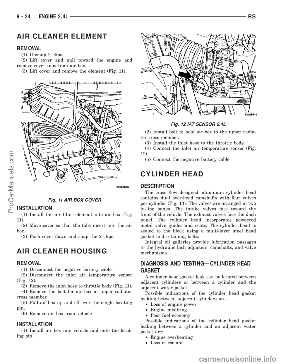
(3) Lift cover and remove the element (Fig. 11).
INSTALLATION
(1) Install the air filter element into air box (Fig.
11).
(2) Move cover so that the tabs insert into the air
box.
(3) Push cover down and snap the 2 clips.
AIR CLEANER HOUSING
REMOVAL
(1) Disconnect the negative battery cable.
(2) Disconnect the inlet air temperature sensor
(Fig. 12).
(3) Remove the inlet hose to throttle body (Fig. 11).
(4) Remove the bolt for air box at upper radiator
cross member.
(5) Pull air box up and off over the single locating
pin.
(6) Remove air box from vehicle
INSTALLATION
(1) Install air box into vehicle and onto the locat-
ing pin.(2) Install bolt to hold air box to the upper radia-
tor cross member.
(3) Install the inlet hose to the throttle body.
(4) Connect the inlet air temperature sensor (Fig.
12).
(5) Connect the negative battery cable.
CYLINDER HEAD
DESCRIPTION
The cross flow designed, aluminum cylinder head
contains dual over-head camshafts with four valves
per cylinder (Fig. 13). The valves are arranged in two
in-line banks. The intake valves face toward the
front of the vehicle. The exhaust valves face the dash
panel. The cylinder head incorporates powdered
metal valve guides and seats. The cylinder head is
sealed to the block using a multi-layer steel head
gasket and retaining bolts.
Integral oil galleries provide lubrication passages
to the hydraulic lash adjusters, camshafts, and valve
mechanisms.
DIAGNOSIS AND TESTINGÐCYLINDER HEAD
GASKET
A cylinder head gasket leak can be located between
adjacent cylinders or between a cylinder and the
adjacent water jacket.
Possible indications of the cylinder head gasket
leaking between adjacent cylinders are:
²Loss of engine power
²Engine misfiring
²Poor fuel economy
Possible indications of the cylinder head gasket
leaking between a cylinder and an adjacent water
jacket are:
²Engine overheating
²Loss of coolant
Fig. 11 AIR BOX COVER
Fig. 12 IAT SENSOR 2.4L
9 - 24 ENGINE 2.4LRS
ProCarManuals.com