2003 CHRYSLER CARAVAN ABS
[x] Cancel search: ABSPage 1058 of 2177
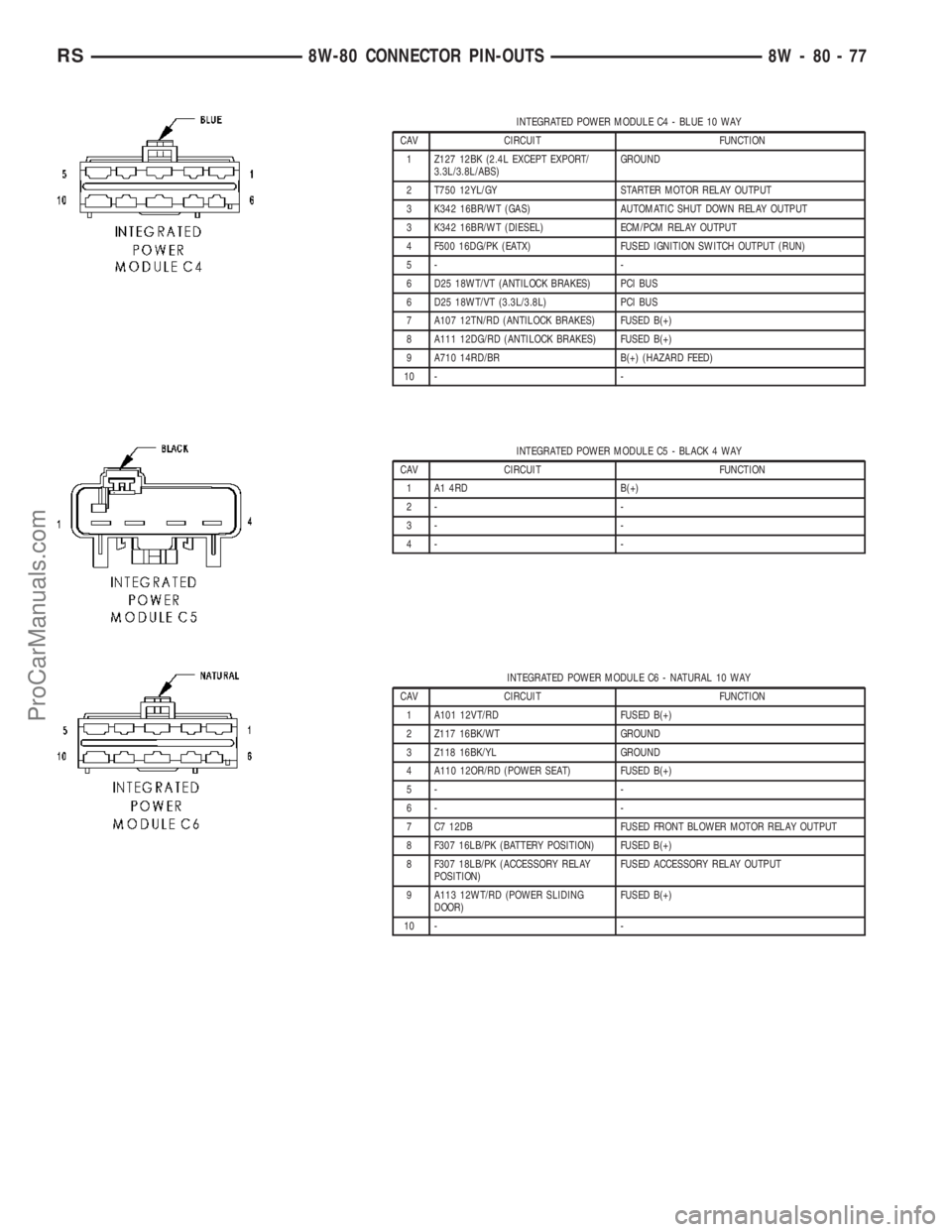
INTEGRATED POWER MODULE C4 - BLUE 10 WAY
CAV CIRCUIT FUNCTION
1 Z127 12BK (2.4L EXCEPT EXPORT/
3.3L/3.8L/ABS)GROUND
2 T750 12YL/GY STARTER MOTOR RELAY OUTPUT
3 K342 16BR/WT (GAS) AUTOMATIC SHUT DOWN RELAY OUTPUT
3 K342 16BR/WT (DIESEL) ECM/PCM RELAY OUTPUT
4 F500 16DG/PK (EATX) FUSED IGNITION SWITCH OUTPUT (RUN)
5- -
6 D25 18WT/VT (ANTILOCK BRAKES) PCI BUS
6 D25 18WT/VT (3.3L/3.8L) PCI BUS
7 A107 12TN/RD (ANTILOCK BRAKES) FUSED B(+)
8 A111 12DG/RD (ANTILOCK BRAKES) FUSED B(+)
9 A710 14RD/BR B(+) (HAZARD FEED)
10 - -
INTEGRATED POWER MODULE C5 - BLACK 4 WAY
CAV CIRCUIT FUNCTION
1 A1 4RD B(+)
2- -
3- -
4- -
INTEGRATED POWER MODULE C6 - NATURAL 10 WAY
CAV CIRCUIT FUNCTION
1 A101 12VT/RD FUSED B(+)
2 Z117 16BK/WT GROUND
3 Z118 16BK/YL GROUND
4 A110 12OR/RD (POWER SEAT) FUSED B(+)
5- -
6- -
7 C7 12DB FUSED FRONT BLOWER MOTOR RELAY OUTPUT
8 F307 16LB/PK (BATTERY POSITION) FUSED B(+)
8 F307 18LB/PK (ACCESSORY RELAY
POSITION)FUSED ACCESSORY RELAY OUTPUT
9 A113 12WT/RD (POWER SLIDING
DOOR)FUSED B(+)
10 - -
RS8W-80 CONNECTOR PIN-OUTS8W-80-77
ProCarManuals.com
Page 1060 of 2177
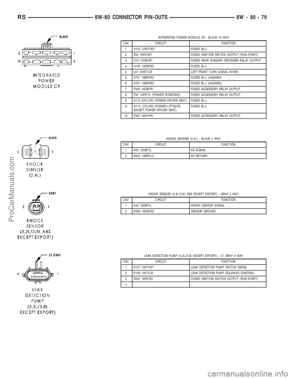
INTEGRATED POWER MODULE C9 - BLACK 10 WAY
CAV CIRCUIT FUNCTION
1 A102 12WT/RD FUSED B(+)
2 F20 18PK/WT FUSED IGNITION SWITCH OUTPUT (RUN-START)
3 C15 12DB/WT FUSED REAR WINDOW DEFOGGER RELAY OUTPUT
4 A105 18DB/RD FUSED B(+)
5 L61 20WT/LB LEFT FRONT TURN SIGNAL DIVER
6 A701 18BR/RD FUSED B(+) (HAZARD)
6 A701 16BR/RD FUSED B(+) (HAZARD)
7 F306 16DB/PK FUSED ACCESSORY RELAY OUTPUT
8 F30 12PK/YL (POWER WINDOWS) FUSED ACCESSORY RELAY OUTPUT
9 A115 20YL/RD (POWER DRIVER SEAT) FUSED B(+)
9 A115 12YL/RD (POWER LIFTGATE/
EXCEPT POWER DRIVER SEAT)FUSED B(+)
10 F302 18GY/PK FUSED ACCESSORY RELAY OUTPUT
KNOCK SENSOR (2.4L) - BLACK 2 WAY
CAV CIRCUIT FUNCTION
1 K42 18DB/YL KS SIGNAL
2 K942 18BR/LG KS RETURN
KNOCK SENSOR (3.3L/3.8L ABS EXCEPT EXPORT) - GRAY 2 WAY
CAV CIRCUIT FUNCTION
1 K42 18DB/YL KNOCK SENSOR SIGNAL
2 K900 18DB/DG SENSOR GROUND
LEAK DETECTION PUMP (3.3L/3.8L EXCEPT EXPORT) - LT. GRAY 4 WAY
CAV CIRCUIT FUNCTION
1 K107 18VT/WT LEAK DETECTION PUMP SWITCH SENSE
2 K106 18VT/LB LEAK DETECTION PUMP SOLENOID CONTROL
3 F202 18PK/GY FUSED IGNITION SWITCH OUTPUT (RUN-START)
4- -
RS8W-80 CONNECTOR PIN-OUTS8W-80-79
ProCarManuals.com
Page 1074 of 2177
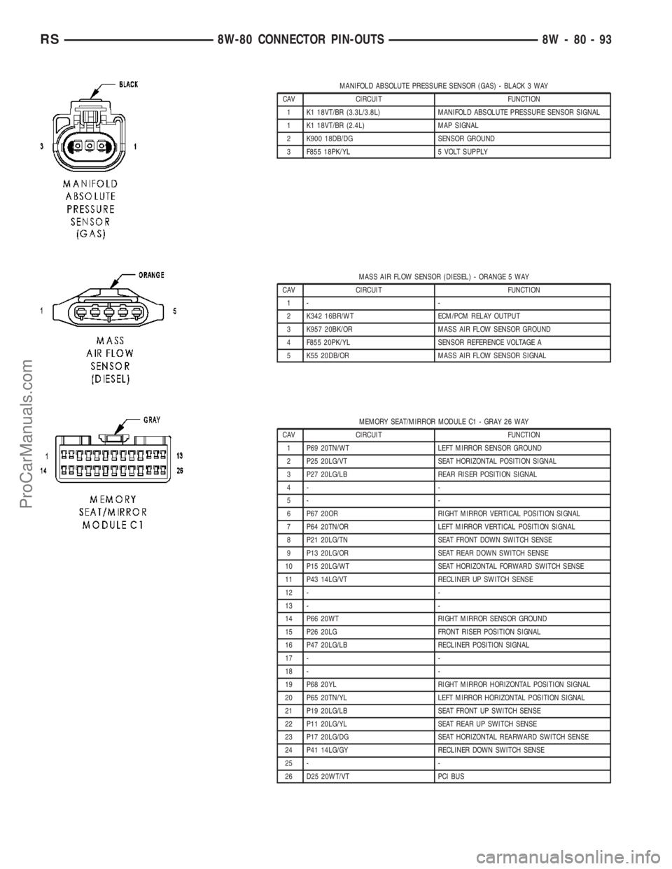
MANIFOLD ABSOLUTE PRESSURE SENSOR (GAS) - BLACK 3 WAY
CAV CIRCUIT FUNCTION
1 K1 18VT/BR (3.3L/3.8L) MANIFOLD ABSOLUTE PRESSURE SENSOR SIGNAL
1 K1 18VT/BR (2.4L) MAP SIGNAL
2 K900 18DB/DG SENSOR GROUND
3 F855 18PK/YL 5 VOLT SUPPLY
MASS AIR FLOW SENSOR (DIESEL) - ORANGE 5 WAY
CAV CIRCUIT FUNCTION
1- -
2 K342 16BR/WT ECM/PCM RELAY OUTPUT
3 K957 20BK/OR MASS AIR FLOW SENSOR GROUND
4 F855 20PK/YL SENSOR REFERENCE VOLTAGE A
5 K55 20DB/OR MASS AIR FLOW SENSOR SIGNAL
MEMORY SEAT/MIRROR MODULE C1 - GRAY 26 WAY
CAV CIRCUIT FUNCTION
1 P69 20TN/WT LEFT MIRROR SENSOR GROUND
2 P25 20LG/VT SEAT HORIZONTAL POSITION SIGNAL
3 P27 20LG/LB REAR RISER POSITION SIGNAL
4- -
5- -
6 P67 20OR RIGHT MIRROR VERTICAL POSITION SIGNAL
7 P64 20TN/OR LEFT MIRROR VERTICAL POSITION SIGNAL
8 P21 20LG/TN SEAT FRONT DOWN SWITCH SENSE
9 P13 20LG/OR SEAT REAR DOWN SWITCH SENSE
10 P15 20LG/WT SEAT HORIZONTAL FORWARD SWITCH SENSE
11 P43 14LG/VT RECLINER UP SWITCH SENSE
12 - -
13 - -
14 P66 20WT RIGHT MIRROR SENSOR GROUND
15 P26 20LG FRONT RISER POSITION SIGNAL
16 P47 20LG/LB RECLINER POSITION SIGNAL
17 - -
18 - -
19 P68 20YL RIGHT MIRROR HORIZONTAL POSITION SIGNAL
20 P65 20TN/YL LEFT MIRROR HORIZONTAL POSITION SIGNAL
21 P19 20LG/LB SEAT FRONT UP SWITCH SENSE
22 P11 20LG/YL SEAT REAR UP SWITCH SENSE
23 P17 20LG/DG SEAT HORIZONTAL REARWARD SWITCH SENSE
24 P41 14LG/GY RECLINER DOWN SWITCH SENSE
25 - -
26 D25 20WT/VT PCI BUS
RS8W-80 CONNECTOR PIN-OUTS8W-80-93
ProCarManuals.com
Page 1087 of 2177
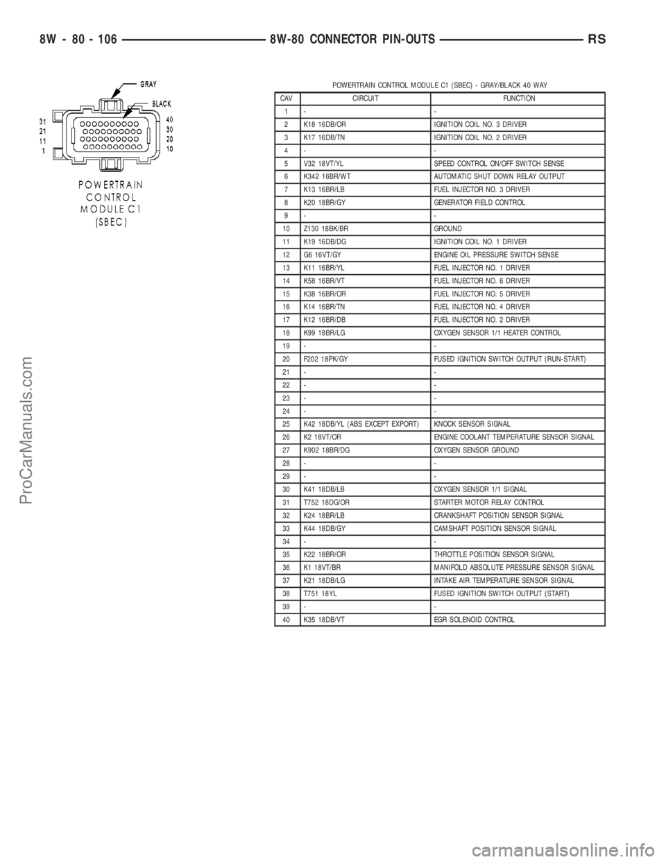
POWERTRAIN CONTROL MODULE C1 (SBEC) - GRAY/BLACK 40 WAY
CAV CIRCUIT FUNCTION
1- -
2 K18 16DB/OR IGNITION COIL NO. 3 DRIVER
3 K17 16DB/TN IGNITION COIL NO. 2 DRIVER
4- -
5 V32 18VT/YL SPEED CONTROL ON/OFF SWITCH SENSE
6 K342 16BR/WT AUTOMATIC SHUT DOWN RELAY OUTPUT
7 K13 16BR/LB FUEL INJECTOR NO. 3 DRIVER
8 K20 18BR/GY GENERATOR FIELD CONTROL
9- -
10 Z130 18BK/BR GROUND
11 K19 16DB/DG IGNITION COIL NO. 1 DRIVER
12 G6 16VT/GY ENGINE OIL PRESSURE SWITCH SENSE
13 K11 16BR/YL FUEL INJECTOR NO. 1 DRIVER
14 K58 16BR/VT FUEL INJECTOR NO. 6 DRIVER
15 K38 16BR/OR FUEL INJECTOR NO. 5 DRIVER
16 K14 16BR/TN FUEL INJECTOR NO. 4 DRIVER
17 K12 16BR/DB FUEL INJECTOR NO. 2 DRIVER
18 K99 18BR/LG OXYGEN SENSOR 1/1 HEATER CONTROL
19 - -
20 F202 18PK/GY FUSED IGNITION SWITCH OUTPUT (RUN-START)
21 - -
22 - -
23 - -
24 - -
25 K42 18DB/YL (ABS EXCEPT EXPORT) KNOCK SENSOR SIGNAL
26 K2 18VT/OR ENGINE COOLANT TEMPERATURE SENSOR SIGNAL
27 K902 18BR/DG OXYGEN SENSOR GROUND
28 - -
29 - -
30 K41 18DB/LB OXYGEN SENSOR 1/1 SIGNAL
31 T752 18DG/OR STARTER MOTOR RELAY CONTROL
32 K24 18BR/LB CRANKSHAFT POSITION SENSOR SIGNAL
33 K44 18DB/GY CAMSHAFT POSITION SENSOR SIGNAL
34 - -
35 K22 18BR/OR THROTTLE POSITION SENSOR SIGNAL
36 K1 18VT/BR MANIFOLD ABSOLUTE PRESSURE SENSOR SIGNAL
37 K21 18DB/LG INTAKE AIR TEMPERATURE SENSOR SIGNAL
38 T751 18YL FUSED IGNITION SWITCH OUTPUT (START)
39 - -
40 K35 18DB/VT EGR SOLENOID CONTROL
8W - 80 - 106 8W-80 CONNECTOR PIN-OUTSRS
ProCarManuals.com
Page 1122 of 2177
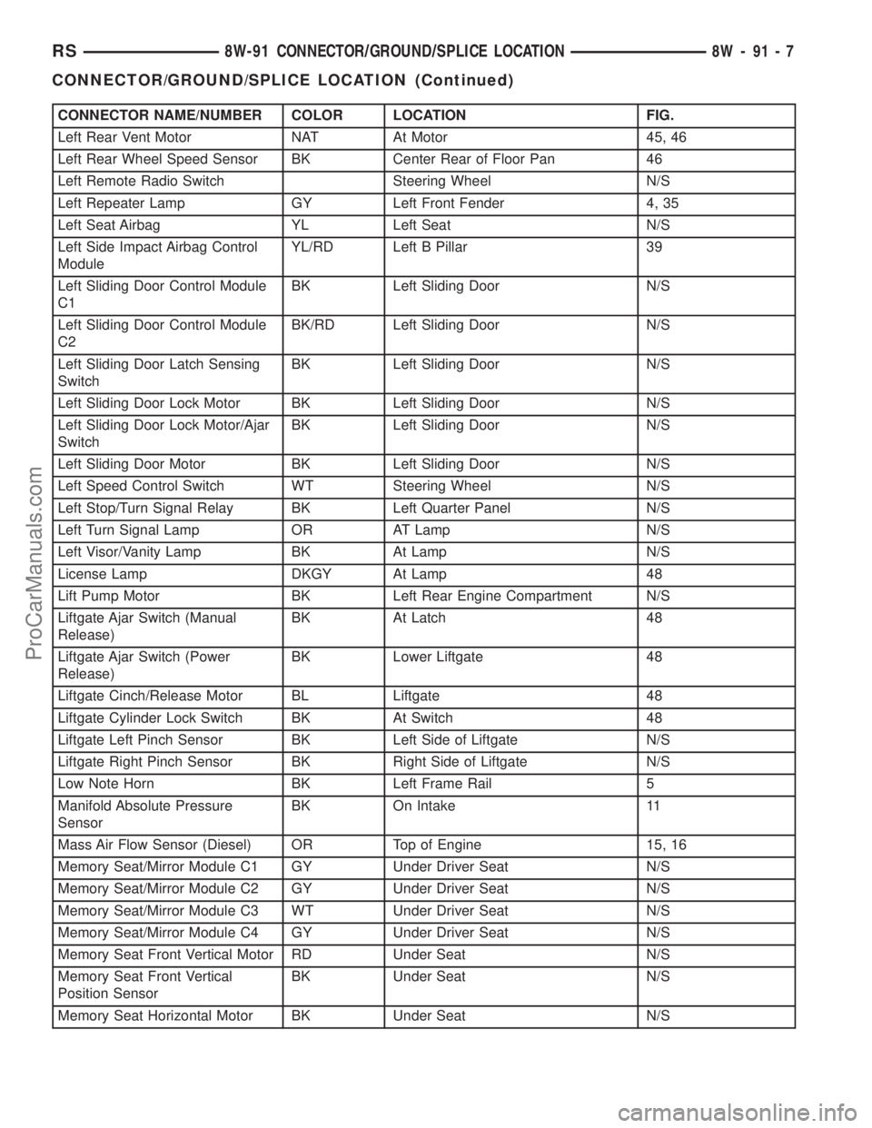
CONNECTOR NAME/NUMBER COLOR LOCATION FIG.
Left Rear Vent Motor NAT At Motor 45, 46
Left Rear Wheel Speed Sensor BK Center Rear of Floor Pan 46
Left Remote Radio Switch Steering Wheel N/S
Left Repeater Lamp GY Left Front Fender 4, 35
Left Seat Airbag YL Left Seat N/S
Left Side Impact Airbag Control
ModuleYL/RD Left B Pillar 39
Left Sliding Door Control Module
C1BK Left Sliding Door N/S
Left Sliding Door Control Module
C2BK/RD Left Sliding Door N/S
Left Sliding Door Latch Sensing
SwitchBK Left Sliding Door N/S
Left Sliding Door Lock Motor BK Left Sliding Door N/S
Left Sliding Door Lock Motor/Ajar
SwitchBK Left Sliding Door N/S
Left Sliding Door Motor BK Left Sliding Door N/S
Left Speed Control Switch WT Steering Wheel N/S
Left Stop/Turn Signal Relay BK Left Quarter Panel N/S
Left Turn Signal Lamp OR AT Lamp N/S
Left Visor/Vanity Lamp BK At Lamp N/S
License Lamp DKGY At Lamp 48
Lift Pump Motor BK Left Rear Engine Compartment N/S
Liftgate Ajar Switch (Manual
Release)BK At Latch 48
Liftgate Ajar Switch (Power
Release)BK Lower Liftgate 48
Liftgate Cinch/Release Motor BL Liftgate 48
Liftgate Cylinder Lock Switch BK At Switch 48
Liftgate Left Pinch Sensor BK Left Side of Liftgate N/S
Liftgate Right Pinch Sensor BK Right Side of Liftgate N/S
Low Note Horn BK Left Frame Rail 5
Manifold Absolute Pressure
SensorBK On Intake 11
Mass Air Flow Sensor (Diesel) OR Top of Engine 15, 16
Memory Seat/Mirror Module C1 GY Under Driver Seat N/S
Memory Seat/Mirror Module C2 GY Under Driver Seat N/S
Memory Seat/Mirror Module C3 WT Under Driver Seat N/S
Memory Seat/Mirror Module C4 GY Under Driver Seat N/S
Memory Seat Front Vertical Motor RD Under Seat N/S
Memory Seat Front Vertical
Position SensorBK Under Seat N/S
Memory Seat Horizontal Motor BK Under Seat N/S
RS8W-91 CONNECTOR/GROUND/SPLICE LOCATION8W-91-7
CONNECTOR/GROUND/SPLICE LOCATION (Continued)
ProCarManuals.com
Page 1128 of 2177

SPLICE NUMBER LOCATION FIG.
S124 (3.3L/3.8L) Near T/O for Fuel Injector No.5 and No.6 N/S
S125 (2.4L) In T/O for Manifold Absolute Pressure Sensor N/S
S126 In Right Headlamp Leveling Assembly N/S
S127 (2.5L) In T/O for Engine Starter Motor N/S
S128 (2.5L) Near T/O for Engine Starter Motor 15
S129 (2.5L) Near T/O for Battery (+) N/S
S130 (2.5L) Near T/O for Battery (+) N/S
S131 Near T/O for Transmission Control Module 11
S131 (3.3L/3.8L) Near T/O for Transmission Control Module N/S
S132 (2.5L) Near T/O for Battery (+) N/S
S133 (2.4L) Near T/O for Integrated Power Module C3 11
S134 (2.5L) IN T/O for Engine Control Module 15
S135 (2.5L) Near T/O for Glow Plug No.2 15
S136 (2.5L) In T/O for Radiator Fan Relays 2
S137 (2.5L) Near T/O for A/C Compressor Clutch 15
S138 (2.5L) Between T/O for Radiator Fan No.2 and T/O for G102 1
S139 (2.5L) Between T/O for Engine Starter Motor and T/O for
Engine Control Module C116
S141 (2.4L) Near T/O for Battery(-) 11
S141 (2.5L) Near T/O for G100 N/S
S141 (3.3L/3.8L) Near T/O for Powertrain Control Module N/S
S142 (3.3L/3.8L) Near T/O for A/C Compressor Clutch 18
S143 (2.5L) Near T/O for Engine Control Module C1 15
S143 (3.3L/3.8L) Near T/O for Integrated Power Module - C3 N/S
S144 (2.5L) Between T/O for Battery Temperature Sensor and T/O
for C10315
S148 (2.5L) Near T/O for Engine Starter Motor 15
S149 (3.3L/3.8L) Near T/O for Transmission Control Module 5
S150 (2.5L) Between T/O for Battery Temperature Sensor and T/O
for C10315
S151 (2.5L) Near T/O for Radiator Fan Relay No.1 2
S152 (2.5L) Near T/O for Radiator Fan No.1 1
S157 (2.5L) Near T/O for Glow Plug No.1 15
S177 In Right Headlamp Wiring Assembly N/S
S179 In Left Headlamp Wiring Assembly N/S
S187 (2.5L) In T/O for Engine Control Module C1 15
S188 (2.5L) Near T/O for Radiator Fan Relay No.1 2
S201 In T/O to Instrument Panel Speaker 19, 25
S202 Near T/O for Instrument Panel Switch Bank 19, 25
S203 Near T/O for Instrument Panel Switch Bank 19, 25
S204 Near T/O to Instrument Panel Speaker 19, 25
S205 Near T/O for C201 19
S206 Near T/O for Instrument Cluster 19
RS8W-91 CONNECTOR/GROUND/SPLICE LOCATION8W-91-13
CONNECTOR/GROUND/SPLICE LOCATION (Continued)
ProCarManuals.com
Page 1190 of 2177
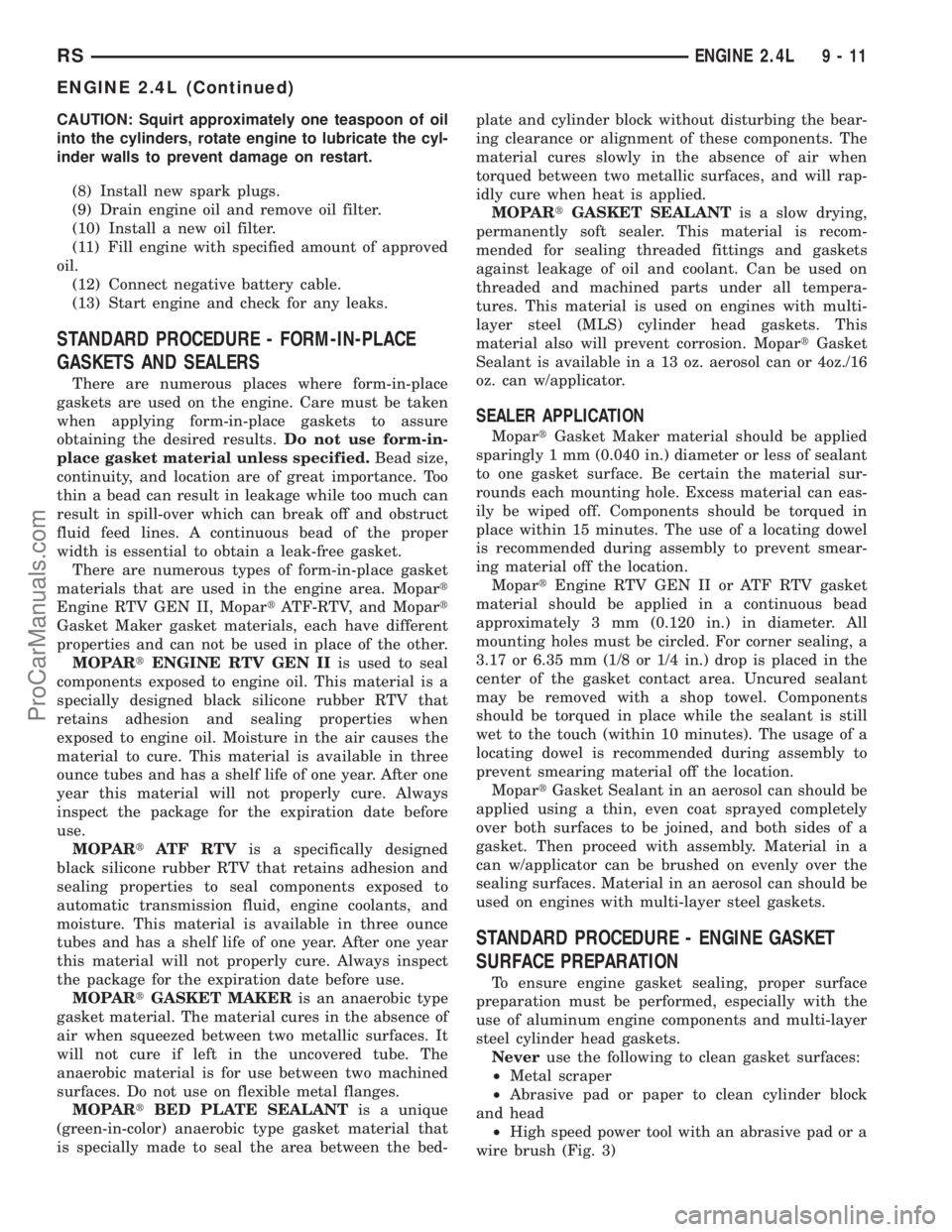
CAUTION: Squirt approximately one teaspoon of oil
into the cylinders, rotate engine to lubricate the cyl-
inder walls to prevent damage on restart.
(8) Install new spark plugs.
(9) Drain engine oil and remove oil filter.
(10) Install a new oil filter.
(11) Fill engine with specified amount of approved
oil.
(12) Connect negative battery cable.
(13) Start engine and check for any leaks.
STANDARD PROCEDURE - FORM-IN-PLACE
GASKETS AND SEALERS
There are numerous places where form-in-place
gaskets are used on the engine. Care must be taken
when applying form-in-place gaskets to assure
obtaining the desired results.Do not use form-in-
place gasket material unless specified.Bead size,
continuity, and location are of great importance. Too
thin a bead can result in leakage while too much can
result in spill-over which can break off and obstruct
fluid feed lines. A continuous bead of the proper
width is essential to obtain a leak-free gasket.
There are numerous types of form-in-place gasket
materials that are used in the engine area. Mopart
Engine RTV GEN II, MopartATF-RTV, and Mopart
Gasket Maker gasket materials, each have different
properties and can not be used in place of the other.
MOPARtENGINE RTV GEN IIis used to seal
components exposed to engine oil. This material is a
specially designed black silicone rubber RTV that
retains adhesion and sealing properties when
exposed to engine oil. Moisture in the air causes the
material to cure. This material is available in three
ounce tubes and has a shelf life of one year. After one
year this material will not properly cure. Always
inspect the package for the expiration date before
use.
MOPARtATF RTVis a specifically designed
black silicone rubber RTV that retains adhesion and
sealing properties to seal components exposed to
automatic transmission fluid, engine coolants, and
moisture. This material is available in three ounce
tubes and has a shelf life of one year. After one year
this material will not properly cure. Always inspect
the package for the expiration date before use.
MOPARtGASKET MAKERis an anaerobic type
gasket material. The material cures in the absence of
air when squeezed between two metallic surfaces. It
will not cure if left in the uncovered tube. The
anaerobic material is for use between two machined
surfaces. Do not use on flexible metal flanges.
MOPARtBED PLATE SEALANTis a unique
(green-in-color) anaerobic type gasket material that
is specially made to seal the area between the bed-plate and cylinder block without disturbing the bear-
ing clearance or alignment of these components. The
material cures slowly in the absence of air when
torqued between two metallic surfaces, and will rap-
idly cure when heat is applied.
MOPARtGASKET SEALANTis a slow drying,
permanently soft sealer. This material is recom-
mended for sealing threaded fittings and gaskets
against leakage of oil and coolant. Can be used on
threaded and machined parts under all tempera-
tures. This material is used on engines with multi-
layer steel (MLS) cylinder head gaskets. This
material also will prevent corrosion. MopartGasket
Sealant is available in a 13 oz. aerosol can or 4oz./16
oz. can w/applicator.
SEALER APPLICATION
MopartGasket Maker material should be applied
sparingly 1 mm (0.040 in.) diameter or less of sealant
to one gasket surface. Be certain the material sur-
rounds each mounting hole. Excess material can eas-
ily be wiped off. Components should be torqued in
place within 15 minutes. The use of a locating dowel
is recommended during assembly to prevent smear-
ing material off the location.
MopartEngine RTV GEN II or ATF RTV gasket
material should be applied in a continuous bead
approximately 3 mm (0.120 in.) in diameter. All
mounting holes must be circled. For corner sealing, a
3.17 or 6.35 mm (1/8 or 1/4 in.) drop is placed in the
center of the gasket contact area. Uncured sealant
may be removed with a shop towel. Components
should be torqued in place while the sealant is still
wet to the touch (within 10 minutes). The usage of a
locating dowel is recommended during assembly to
prevent smearing material off the location.
MopartGasket Sealant in an aerosol can should be
applied using a thin, even coat sprayed completely
over both surfaces to be joined, and both sides of a
gasket. Then proceed with assembly. Material in a
can w/applicator can be brushed on evenly over the
sealing surfaces. Material in an aerosol can should be
used on engines with multi-layer steel gaskets.
STANDARD PROCEDURE - ENGINE GASKET
SURFACE PREPARATION
To ensure engine gasket sealing, proper surface
preparation must be performed, especially with the
use of aluminum engine components and multi-layer
steel cylinder head gaskets.
Neveruse the following to clean gasket surfaces:
²Metal scraper
²Abrasive pad or paper to clean cylinder block
and head
²High speed power tool with an abrasive pad or a
wire brush (Fig. 3)
RSENGINE 2.4L9-11
ENGINE 2.4L (Continued)
ProCarManuals.com
Page 1203 of 2177
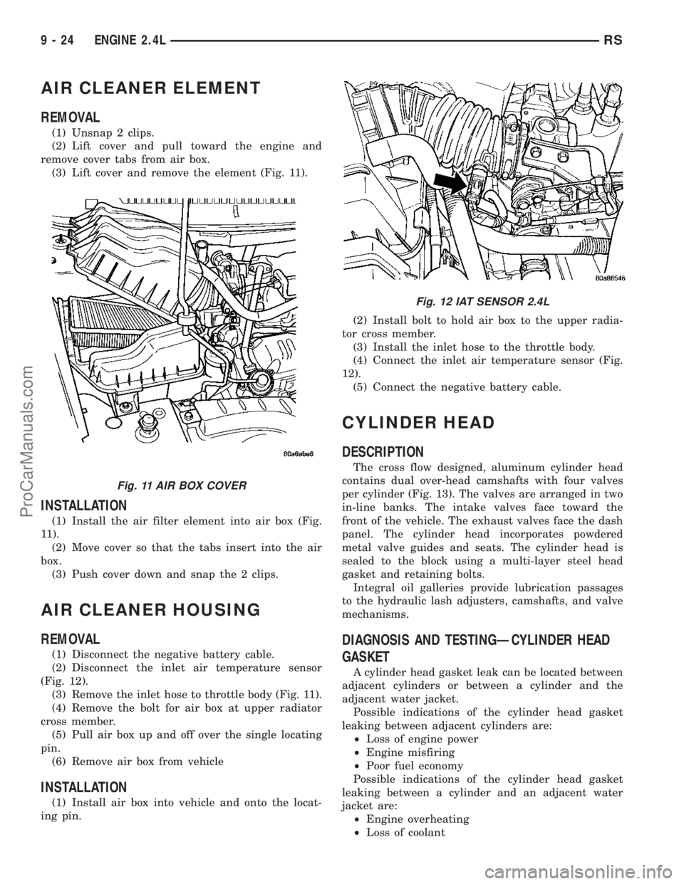
AIR CLEANER ELEMENT
REMOVAL
(1) Unsnap 2 clips.
(2) Lift cover and pull toward the engine and
remove cover tabs from air box.
(3) Lift cover and remove the element (Fig. 11).
INSTALLATION
(1) Install the air filter element into air box (Fig.
11).
(2) Move cover so that the tabs insert into the air
box.
(3) Push cover down and snap the 2 clips.
AIR CLEANER HOUSING
REMOVAL
(1) Disconnect the negative battery cable.
(2) Disconnect the inlet air temperature sensor
(Fig. 12).
(3) Remove the inlet hose to throttle body (Fig. 11).
(4) Remove the bolt for air box at upper radiator
cross member.
(5) Pull air box up and off over the single locating
pin.
(6) Remove air box from vehicle
INSTALLATION
(1) Install air box into vehicle and onto the locat-
ing pin.(2) Install bolt to hold air box to the upper radia-
tor cross member.
(3) Install the inlet hose to the throttle body.
(4) Connect the inlet air temperature sensor (Fig.
12).
(5) Connect the negative battery cable.
CYLINDER HEAD
DESCRIPTION
The cross flow designed, aluminum cylinder head
contains dual over-head camshafts with four valves
per cylinder (Fig. 13). The valves are arranged in two
in-line banks. The intake valves face toward the
front of the vehicle. The exhaust valves face the dash
panel. The cylinder head incorporates powdered
metal valve guides and seats. The cylinder head is
sealed to the block using a multi-layer steel head
gasket and retaining bolts.
Integral oil galleries provide lubrication passages
to the hydraulic lash adjusters, camshafts, and valve
mechanisms.
DIAGNOSIS AND TESTINGÐCYLINDER HEAD
GASKET
A cylinder head gasket leak can be located between
adjacent cylinders or between a cylinder and the
adjacent water jacket.
Possible indications of the cylinder head gasket
leaking between adjacent cylinders are:
²Loss of engine power
²Engine misfiring
²Poor fuel economy
Possible indications of the cylinder head gasket
leaking between a cylinder and an adjacent water
jacket are:
²Engine overheating
²Loss of coolant
Fig. 11 AIR BOX COVER
Fig. 12 IAT SENSOR 2.4L
9 - 24 ENGINE 2.4LRS
ProCarManuals.com