2003 CHRYSLER CARAVAN wheel bolt torque
[x] Cancel search: wheel bolt torquePage 1749 of 2177
INSTALLATION
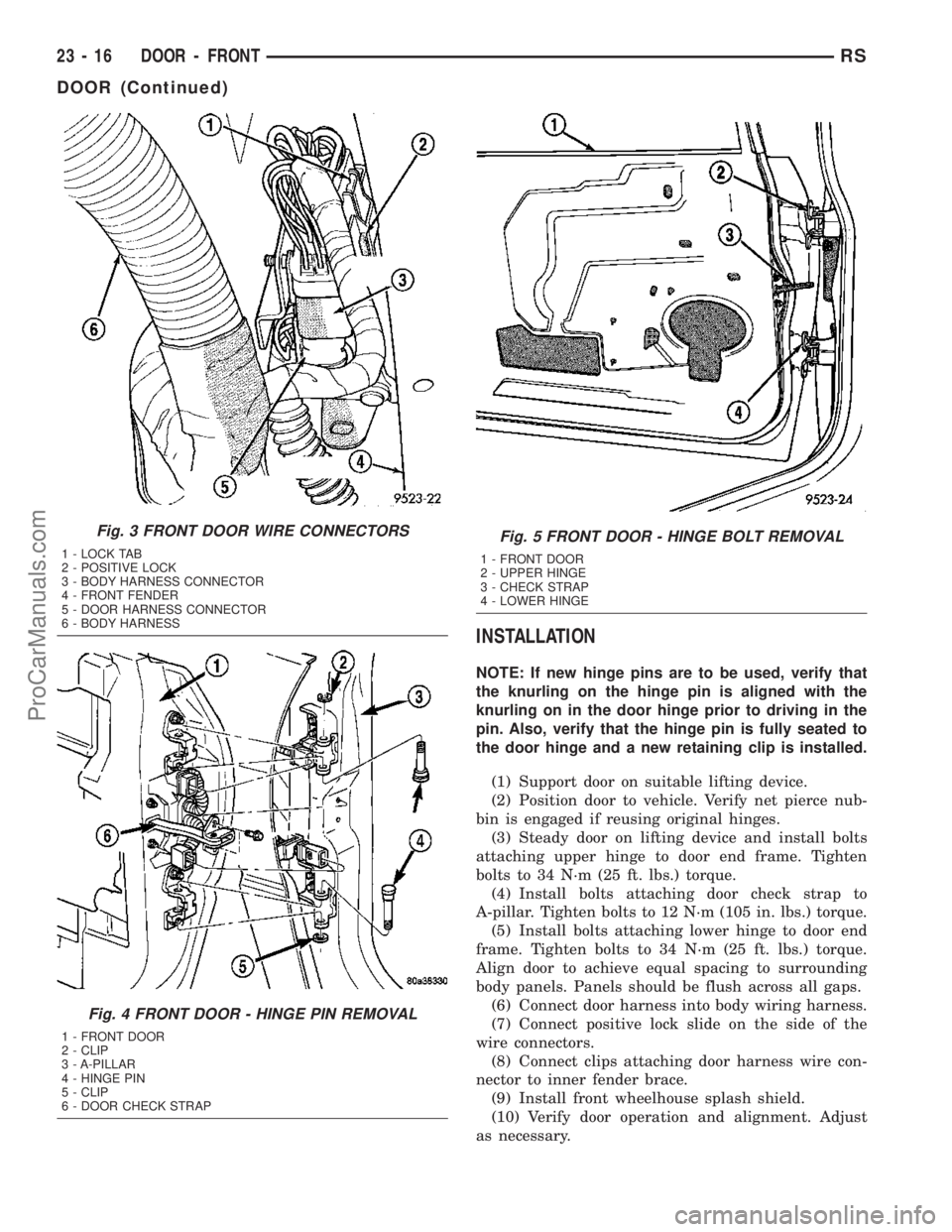
NOTE: If new hinge pins are to be used, verify that
the knurling on the hinge pin is aligned with the
knurling on in the door hinge prior to driving in the
pin. Also, verify that the hinge pin is fully seated to
the door hinge and a new retaining clip is installed.
(1) Support door on suitable lifting device.
(2) Position door to vehicle. Verify net pierce nub-
bin is engaged if reusing original hinges.
(3) Steady door on lifting device and install bolts
attaching upper hinge to door end frame. Tighten
bolts to 34 N´m (25 ft. lbs.) torque.
(4) Install bolts attaching door check strap to
A-pillar. Tighten bolts to 12 N´m (105 in. lbs.) torque.
(5) Install bolts attaching lower hinge to door end
frame. Tighten bolts to 34 N´m (25 ft. lbs.) torque.
Align door to achieve equal spacing to surrounding
body panels. Panels should be flush across all gaps.
(6) Connect door harness into body wiring harness.
(7) Connect positive lock slide on the side of the
wire connectors.
(8) Connect clips attaching door harness wire con-
nector to inner fender brace.
(9) Install front wheelhouse splash shield.
(10) Verify door operation and alignment. Adjust
as necessary.
Fig. 3 FRONT DOOR WIRE CONNECTORS
1 - LOCK TAB
2 - POSITIVE LOCK
3 - BODY HARNESS CONNECTOR
4 - FRONT FENDER
5 - DOOR HARNESS CONNECTOR
6 - BODY HARNESS
Fig. 4 FRONT DOOR - HINGE PIN REMOVAL
1 - FRONT DOOR
2 - CLIP
3 - A-PILLAR
4 - HINGE PIN
5 - CLIP
6 - DOOR CHECK STRAP
Fig. 5 FRONT DOOR - HINGE BOLT REMOVAL
1 - FRONT DOOR
2 - UPPER HINGE
3 - CHECK STRAP
4 - LOWER HINGE
23 - 16 DOOR - FRONTRS
DOOR (Continued)
ProCarManuals.com
Page 1787 of 2177

(3) Align with paint breaks around bolt heads.
(4) Install bolts attaching ends of crossmember to
radiator closure panel (Fig. 14). Tighten bolts to 19
N´m (14 ft. lbs.) torque.
(5) Install bolts attaching radiator isolators to
crossmember.
(6) Install screw attaching coolant recovery bottle
to crossmember.
(7) Install bolt attaching air cleaner housing to
crossmember.
(8) Install engine air inlet resonator.
(9) Install radiator sight shield.
(10) Install hood prop rod.
(11) Align hood latch by placing latch over net
pierce tabs. If alignment is required, flatten tabs.
(12) Install bolts attaching hood latch to cross-
member. Tighten bolts to 13.5 N´m (10 ft. lbs.)
torque.
(13) Verify hood latch operation and hood align-
ment.
FRONT WHEELHOUSE
SPLASH SHIELD
REMOVAL
(1) Hoist and support vehicle on safety stands.
(Refer to LUBRICATION & MAINTENANCE/HOIST-
ING - STANDARD PROCEDURE).
(2) Remove front wheel.
(3) Remove push pin fasteners attaching splash
shield to frame rail forward of suspension.
(4) Remove push pin fasteners attaching splash
shield to frame rail rearward of suspension.
(5) Remove screws attaching wheelhouse splash
shield to front fender and front bumper fascia.
(6) Remove splash shield from vehicle (Fig. 15).
INSTALLATION
(1) Place splash shield in position on vehicle (Fig.
15).
(2) Install push pin fasteners attaching splash
shield to frame rail forward of suspension.
(3) Install push pin fasteners attaching splash
shield to frame rail rearward of suspension.
(4) Install screws attaching wheelhouse splash
shield to front fender.
(5) Install front wheel.
(6) Lower vehicle.
LUGGAGE RACK RISER
REMOVAL
(1) Remove two fasteners from the front riser.
Gently pull up on the luggage rack side rail and
detach the riser snap to remove riser from the rail
(Fig. 16).
(2) Repeat for the opposite side, if necessary.
(3) Remove front riser(s) from vehicle (Fig. 17).
Fig. 15 FRONT WHEELHOUSE SPLASH SHIELD
1 - FRONT FENDER WHEELHOUSE SPLASH SHIELD
2 - PUSH PIN FASTENERS
3 - ACCESSORY DRIVE SPLASH SHIELD
4 - SCREWS
Fig. 16 LUGGAGE RACK RISER COVER
1 - FRONT RISER COVER
2 - LOCK TABS
3 - LUGGAGE RACK SIDE RAIL
4 - FRONT RISER
23 - 54 EXTERIORRS
GRILLE OPENING REINFORCEMENT (Continued)
ProCarManuals.com
Page 1811 of 2177
(2) Engage hook retainer attaching front of trim
bolster to quarter trim panel, if applicable.
(3) Engage hidden clips attaching trim bolster to
quarter trim panel.
RIGHT QUARTER TRIM PANEL
REMOVAL
CAUTION: Disconnect the battery negative cable.
Damage to accessory feed circuit can result.
(1) Remove first row seat.
(2) Remove second row seat.
(3) Remove sliding door sill trim panel.
(4) Remove quarter trim bolster.
(5) Remove D-pillar trim panel.
(6) Remove first row seat belt anchor.
(7) Remove second row seat belt anchor.
(8) Remove screws attaching quarter trim to quar-
ter panel from bolster area.
(9) Remove screws attaching rear edge of quarter
trim to attaching bracket.
(10) Disengage hidden clips attaching front of
quarter trim to quarter panel rearward of sliding
door opening and at locators.
(11) Remove quarter trim from quarter panel.
(12) Disconnect speaker wire connector on LWB
quarter trim panel with rear air conditioning.
(13) Pass second row seat belt through slot in trim
panel on long wheel base vehicle.
(14) Pass first row seat belt through slot in trim
panel.
(15) Remove quarter trim panel from vehicle.
INSTALLATION
(1) Position quarter trim panel on vehicle.
(2) Pass first row seat belt through slot in trim
panel.
(3) Pass second row seat belt through access hole
in trim panel on long wheel base vehicle.
(4) Connect wire connector into speaker on LWB
with rear air conditioning.
(5) Align locating pins on backside of trim panel to
mating holes in inner quarter panel.
(6) Engage hidden clips attaching front of quarter
trim to quarter panel rearward of sliding door open-
ing and at locators.
(7) Install screws attaching rear edge of quarter
trim to attaching bracket.
(8) Install screws attaching quarter trim to inner
quarter panel in bolster area.
(9) Install second row seat belt anchor on long
wheel base vehicle. Tighten all seat belt bolts to 39
N´m (29 ft. lbs.) torque.
(10) Install first row seat belt anchor.(11) Install D-pillar trim panel.
(12) Install C-pillar trim panel.
(13) Install quarter trim bolster.
(14) Install sliding door sill trim panel.
(15) Install second row seat, if equipped.
(16) Install first row seat.
(17) Connect the battery negative cable.
LEFT QUARTER TRIM PANEL
REMOVAL
CAUTION: Disconnect the negative cable clamp
from battery post. Damage to accessory feed circuit
can result.
(1) Remove first row seat.
(2) Remove second row seat, if equipped.
(3) Remove front door sill plate on three door vehi-
cle.
(4) Remove sliding door sill plate on four door
vehicle.
(5) Remove left quarter trim bolster.
(6) Remove C-pillar trim panel.
(7) Remove left D-pillar trim panel.
(8) Remove first row seat belt anchor.
(9) Remove second row seat belt anchor on long
wheel base vehicle.
(10) Remove screws attaching quarter trim to
quarter panel from bolster area.
(11) Remove screws attaching rear edge of quarter
trim to attaching bracket or inner quarter trim
panel.
(12) Disconnect wire connector from accessory
power outlet, if equipped.
(13) Remove quarter trim from quarter panel.
(14) Pass front seat belt and turning loop through
slot in quarter trim panel on three door vehicle.
(15) Pass first row seat belt through slot in quar-
ter trim panel.
(16) Pass second row seat belt, if equipped,
through slot in quarter trim panel on long wheel
base vehicle.
(17) Remove quarter trim panel from vehicle.
INSTALLATION
(1) Position quarter trim panel on vehicle.
(2) Pass second row seat belt, if equipped, through
slot in quarter trim panel on long wheel base vehicle.
(3) Pass first row seat belt through slot in quarter
trim panel.
(4) Connect wire connector into accessory power
outlet, if equipped.
(5) Align locating pins on backside of trim panel to
mating holes in inner panels.
23 - 78 INTERIORRS
QUARTER TRIM BOLSTER (Continued)
ProCarManuals.com
Page 1812 of 2177
(6) Position quarter trim panel on inner quarter
panel.
(7) Install screws attaching rear edge of quarter
trim to attaching bracket or inner quarter panel.
(8) Install screws attaching quarter trim to inner
quarter panel in bolster area.
(9) Install second row seat belts anchor on long
wheel base vehicle. Tighten all seat belt bolts to 39
N´m (28 in. lbs.) torque.
(10) Install first row seat belt anchor.
(11) Install left D-pillar trim panel.
(12) Install C-pillar trim panel.
(13) Install upper left B-pillar trim on three door
vehicle.
(14) Install left quarter trim bolster.
(15) Install front door sill plate on three door vehi-
cle.
(16) Install sliding door sill plate on four door
vehicle.
(17) Install second row seat, if equipped.
(18) Install first row seat.
(19) Connect the battery negative cable.
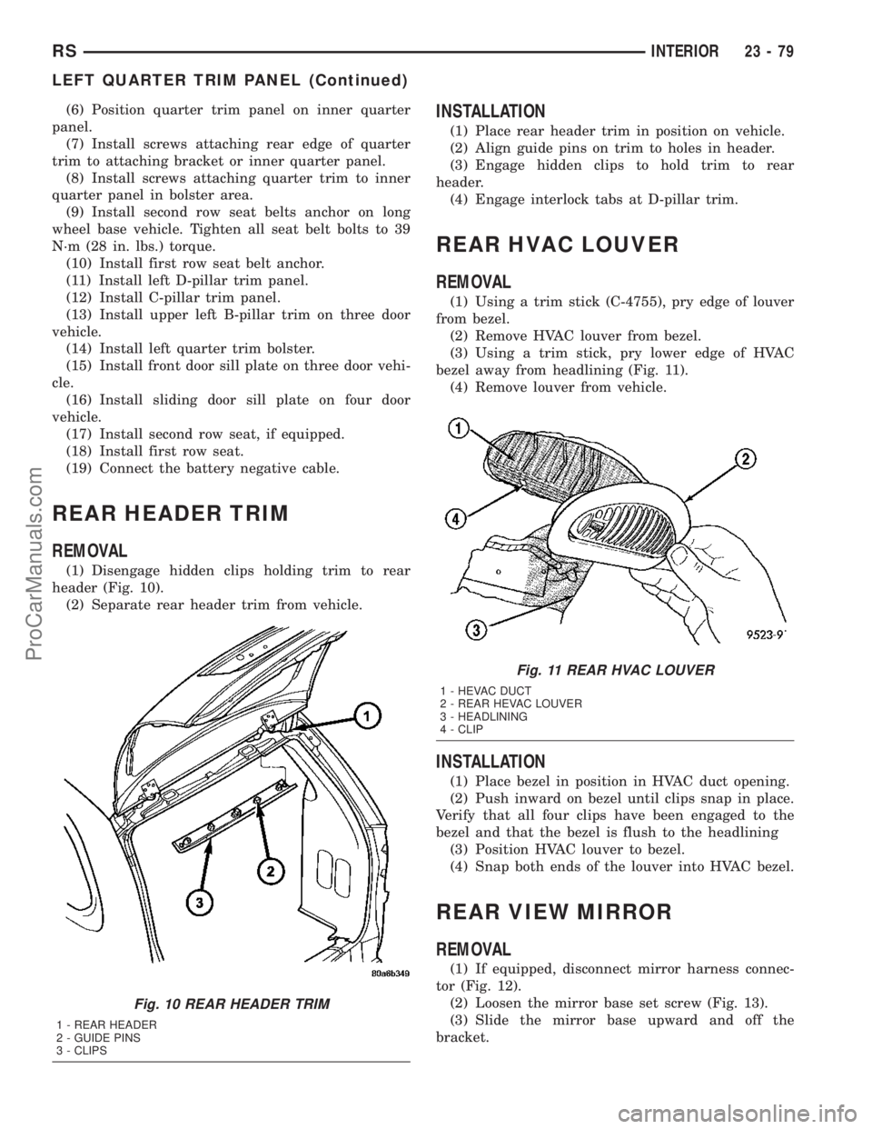
REAR HEADER TRIM
REMOVAL
(1) Disengage hidden clips holding trim to rear
header (Fig. 10).
(2) Separate rear header trim from vehicle.
INSTALLATION
(1) Place rear header trim in position on vehicle.
(2) Align guide pins on trim to holes in header.
(3) Engage hidden clips to hold trim to rear
header.
(4) Engage interlock tabs at D-pillar trim.
REAR HVAC LOUVER
REMOVAL
(1) Using a trim stick (C-4755), pry edge of louver
from bezel.
(2) Remove HVAC louver from bezel.
(3) Using a trim stick, pry lower edge of HVAC
bezel away from headlining (Fig. 11).
(4) Remove louver from vehicle.
INSTALLATION
(1) Place bezel in position in HVAC duct opening.
(2) Push inward on bezel until clips snap in place.
Verify that all four clips have been engaged to the
bezel and that the bezel is flush to the headlining
(3) Position HVAC louver to bezel.
(4) Snap both ends of the louver into HVAC bezel.
REAR VIEW MIRROR
REMOVAL
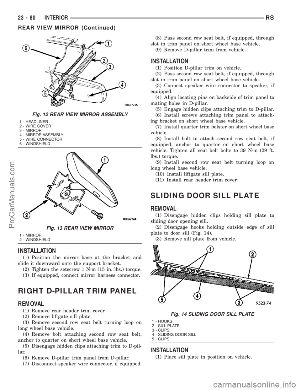
(1) If equipped, disconnect mirror harness connec-
tor (Fig. 12).
(2) Loosen the mirror base set screw (Fig. 13).
(3) Slide the mirror base upward and off the
bracket.
Fig. 10 REAR HEADER TRIM
1 - REAR HEADER
2 - GUIDE PINS
3 - CLIPS
Fig. 11 REAR HVAC LOUVER
1 - HEVAC DUCT
2 - REAR HEVAC LOUVER
3 - HEADLINING
4 - CLIP
RSINTERIOR23-79
LEFT QUARTER TRIM PANEL (Continued)
ProCarManuals.com
Page 1813 of 2177
INSTALLATION
(1) Position the mirror base at the bracket and
slide it downward onto the support bracket.
(2) Tighten the setscrew 1 N´m (15 in. lbs.) torque.
(3) If equipped, connect mirror harness connector.
RIGHT D-PILLAR TRIM PANEL
REMOVAL
(1) Remove rear header trim cover.
(2) Remove liftgate sill plate.
(3) Remove second row seat belt turning loop on
long wheel base vehicle.
(4) Remove bolt attaching second row seat belt,
anchor to quarter on short wheel base vehicle.
(5) Disengage hidden clips attaching trim to D-pil-
lar.
(6) Remove D-pillar trim panel from D-pillar.
(7) Disconnect speaker wire connector, if equipped.(8) Pass second row seat belt, if equipped, through
slot in trim panel on short wheel base vehicle.
(9) Remove D-pillar trim from vehicle.
INSTALLATION
(1) Position D-pillar trim on vehicle.
(2) Pass second row seat belt, if equipped, through
slot in trim panel on short wheel base vehicle.
(3) Connect speaker wire connector to speaker, if
equipped.
(4) Align locating pins on backside of trim panel to
mating holes in D-pillar.
(5) Engage hidden clips attaching trim to D-pillar.
(6) Install screws attaching trim panel to attach-
ing bracket on short wheel base vehicle.
(7) Install quarter trim bolster on short wheel base
vehicle.
(8) Install bolt to attach second row seat belt, if
equipped, anchor to quarter on short wheel base
vehicle. Tighten all seat belt bolts to 39 N´m (29 ft.
lbs.) torque.
(9) Install second row seat belt turning loop on
long wheel base vehicle.
(10) Install liftgate sill plate.
(11) Install rear header trim cover.
SLIDING DOOR SILL PLATE
REMOVAL
(1) Disengage hidden clips holding sill plate to
sliding door opening sill.
(2) Disengage hooks holding outside edge of sill
plate to door sill (Fig. 14).
(3) Remove sill plate from vehicle.
INSTALLATION
(1) Place sill plate in position on vehicle.
Fig. 12 REAR VIEW MIRROR ASSEMBLY
1 - HEADLINER
2 - WIRE COVER
3 - MIRROR
4 - MIRROR ASSEMBLY
5 - WIRE CONNECTOR
6 - WINDSHIELD
Fig. 13 REAR VIEW MIRROR
1 - MIRROR
2 - WINDSHIELD
Fig. 14 SLIDING DOOR SILL PLATE
1 - HOOKS
2 - SILL PLATE
3 - CLIPS
4 - SLIDING DOOR SILL
5 - CLIPS
23 - 80 INTERIORRS
REAR VIEW MIRROR (Continued)
ProCarManuals.com
Page 2014 of 2177
damaged, the clutch electromagnetic coil unit must
be replaced.
OPERATION
The compressor clutch components provide the
means to engage and disengage the compressor from
the engine serpentine accessory drive belt. When the
clutch coil is energized, it magnetically draws the
clutch plate into contact with the clutch pulley and
drives the compressor shaft. When the coil is not
energized, the pulley freewheels on the clutch hub
bearing, which is part of the pulley.
A zener diode is connected in parallel with the
clutch electromagnetic coil. This diode controls the
dissipation of voltage induced into the coil windings
by the collapsing of the electromagnetic fields that
occurs when the compressor clutch is disengaged.
The zener diode dissipates this induced voltage by
regulating a current path to ground. This arrange-
ment serves to protect other circuits and components
from potentially damaging voltage spikes in the vehi-
cle electrical system that might occur if the voltage
induced in the clutch coil windings could not be dis-
sipated.
The compressor clutch engagement is controlled by
several components: the heater-A/C controls in the
passenger compartment, the A/C pressure transducer
on the liquid line, the evaporator temperature sensor
on the expansion valve, the Powertrain Control Mod-
ule (PCM) in the engine compartment, and the com-
pressor clutch relay in the Intelligent Power Module
(IPM). The PCM may delay compressor clutch
engagement for up to thirty seconds. (Refer to 8 -
ELECTRICAL/ELECTRONIC CONTROL MOD-ULES/POWERTRAIN CONTROL MODULE -
DESCRIPTION - PCM OPERATION).
STANDARD PROCEDURE
STANDARD PROCEDURE - COMPRESSOR
CLUTCH AIR GAP
If a new clutch plate and/or clutch pulley are being
used, the air gap between the clutch plate and clutch
pulley must be checked using the following proce-
dure:
(1) Using feeler gauges, measure the air gap
between the clutch plate and the clutch pulley fric-
tion surfaces.
(2) If the air gap is not between 0.5 and 0.9 mm
(0.020 and 0.035 in.), add or subtract shims until the
desired air gap is obtained.
NOTE: The shims may compress after tightening
the compressor shaft bolt. Check the air gap in four
or more places on the clutch plate to verify that the
air gap is still correct. Spin the clutch pulley before
making the final air gap check.
STANDARD PROCEDURE - COMPRESSOR
CLUTCH BREAK-IN
After a new compressor clutch has been installed,
check that the compressor clutch coil is performing to
specifications. (Refer to 24 - HEATING & AIR CON-
DITIONING/CONTROLS - FRONT/COMPRESSOR
CLUTCH COIL - DIAGNOSIS AND TESTING). If
the clutch coil is performing to specifications, per-
form the compressor clutch break-in procedure. This
procedure (burnishing) will seat the opposing friction
surfaces and provide a higher compressor clutch
torque capability.
(1) Set the heater-A/C controls to the A/C mode,
with the blower switch in the highest speed position.
(2) Start the engine and hold the engine speed at
1500 to 2000 rpm.
(3) Cycle the compressor clutch On and Off about
twenty times (seven seconds On, then seven seconds
Off).
REMOVAL
The refrigerant system can remain fully charged
during compressor clutch, pulley, or coil replacement.
Although the compressor assembly must be removed
from its mounting, the compressor clutch can be ser-
vice with the compressor in the vehicle.
(1) Disconnect and isolate the battery negative
cable.
(2) Raise and support the vehicle.
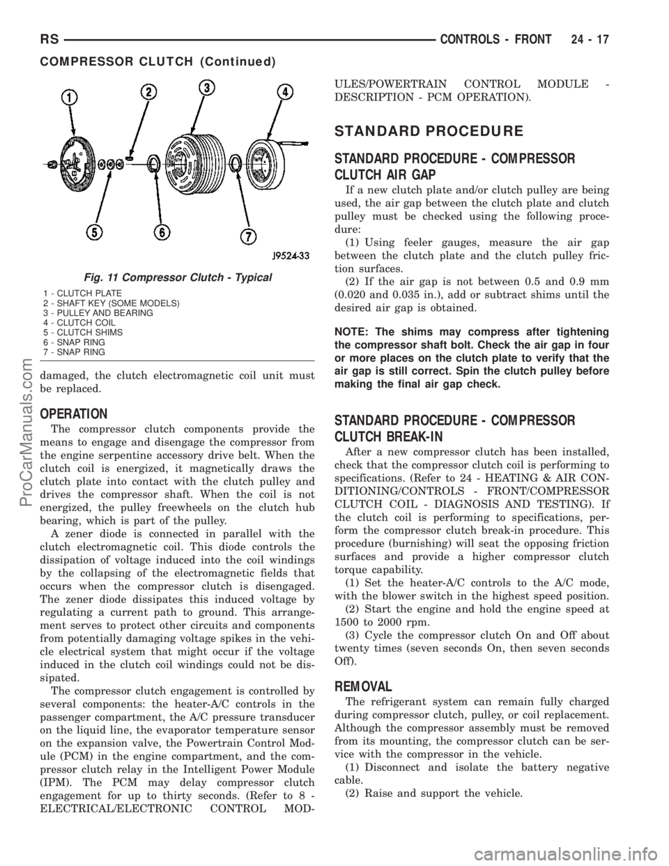
Fig. 11 Compressor Clutch - Typical
1 - CLUTCH PLATE
2 - SHAFT KEY (SOME MODELS)
3 - PULLEY AND BEARING
4 - CLUTCH COIL
5 - CLUTCH SHIMS
6 - SNAP RING
7 - SNAP RING
RSCONTROLS - FRONT24-17
COMPRESSOR CLUTCH (Continued)
ProCarManuals.com