Page 10 of 30

10
EWS
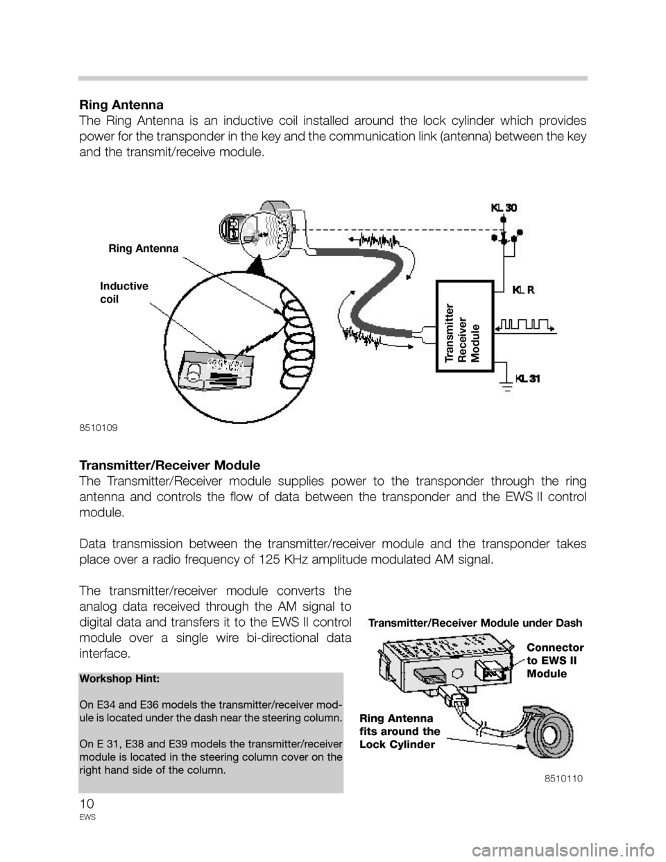
Ring Antenna
The Ring Antenna is an inductive coil installed around the lock cylinder which provides
power for the transponder in the key and the communication link (antenna) between the key
and the transmit/receive module.
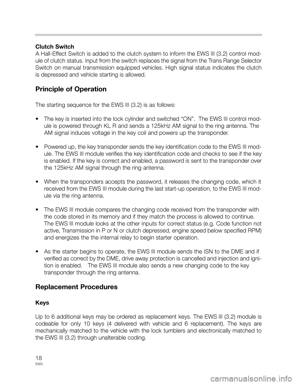
Transmitter/Receiver Module
The Transmitter/Receiver module supplies power to the transponder through the ring
antenna and controls the flow of data between the transponder and the EWS II control
module.
Data transmission between the transmitter/receiver module and the transponder takes
place over a radio frequency of 125 KHz amplitude modulated AM signal.
The transmitter/receiver module converts the
analog data received through the AM signal to
digital data and transfers it to the EWS II control
module over a single wire bi-directional data
interface.
8510109
8510110
Workshop Hint:
On E34 and E36 models the transmitter/receiver mod-
ule is located under the dash near the steering column.
On E 31, E38 and E39 models the transmitter/receiver
module is located in the steering column cover on the
right hand side of the column.
Inductive
coil
Ring Antenna
Transmitter
Receiver
Module
Transmitter/Receiver Module under Dash
Connector
to EWS II
Module
Ring Antenna
fits around the
Lock Cylinder
Page 18 of 30

18
EWS
Clutch Switch
A Hall-Effect Switch is added to the clutch system to inform the EWS III (3.2) control mod-
ule of clutch status. Input from the switch replaces the signal from the Trans Range Selector
Switch on manual transmission equipped vehicles. High signal status indicates the clutch
is depressed and vehicle starting is allowed.
Principle of Operation
The starting sequence for the EWS III (3.2) is as follows:
• The key is inserted into the lock cylinder and switched “ON”. The EWS III control mod-
ule is powered through KL R and sends a 125kHz AM signal to the ring antenna. The
AM signal induces voltage in the key coil and powers up the transponder.
• Powered up, the key transponder sends the key identification code to the EWS III mod-
ule. The EWS III module verifies the key identification code and checks to see if the key
is enabled. If the key is correct and enabled, a password is sent to the transponder over
the 125kHz AM signal through the ring antenna.
• When the transponders accepts the password, it releases the changing code, which it
received from the EWS III module during the last start-up operation, to the EWS III mod-
ule via the ring antenna.
• The EWS III module compares the changing code received from the transponder with
the code stored in its memory and if they match the process is allowed to continue.
The EWS III module looks at the other inputs for correct status (e.g. Code function not
active, Transmission in P or N or clutch depressed, engine speed below specified RPM)
and energizes the the internal relay to begin starter operation.
• As the starter begins to operate, the EWS III module sends the ISN to the DME and if
verified as correct by the DME, drive away protection is cancelled and injection and igni-
tion is enabled. The EWS III module also sends a new changing code to the key
transponder through the ring antenna.
Replacement Procedures
Keys
Up to 6 additional keys may be ordered as replacement keys. The EWS III (3.2) module is
codeable for only 10 keys (4 delivered with vehicle and 6 replacement). The keys are
mechanically matched to the vehicle with the lock tumblers and electronically matched to
the EWS III (3.2) through unalterable coding.
Page 21 of 30

21
EWS
DME Control Module
The DME Control Module has changed in that it is not the source of the ISN but now only
stores the “Rolling Code”. It compares the “Codes” to those sent to it by the EWS III (3.3)
control module. The “Rolling Code Table” assigned to the DME must match the table in the
EWS III (3.3) module. The “Rolling Code Table is “burned” into the DME during the pro-
gramming of the DME and cannot be change once “burned”.
Transmission Range Selection Input
With the introduction of the SKE type connectors on Transmission Control Modules the
direct input from the Transmission Range Selector Switch is eliminated. The input for range
selection is now received from the AGS Control Module.
On manual transmission vehicles clutch status is input directly into the DME.
Principle of Operation
The starting sequence of the EWS III (3.3) is as follows:
(Same as EWS III (3.2)
• The key is inserted into the lock cylinder and switched “ON”. The EWS III (3.3) control
module is powered through KL R and sends a 125kHz AM signal to the ring antenna.
The AM signal induces voltage in the key coil and powers up the transponder.
• Powered up, the key transponder sends the key identification code to the EWS III (3.3)
module. The EWS III (3.3) module verifies the key identification code and checks to see
if the key is enabled. If the key is correct and enabled, a password is sent to the
transponder over the 125kHz AM signal through the ring antenna.
• When the transponders accepts the password, it releases the changing code which it
received from the EWS III (3.3) module during the last start-up operation to the EWS III
(3.3) module via the ring antenna.
• The EWS III (3.3) module compares the changing code received from the transponder
with the code stored in its memory and if they match the process is allowed to contin-
ue. The EWS III (3.3) module looks at the other inputs for correct status (e.g. Code func-
tion not active, Transmission in P or N or clutch depressed, engine speed below spec-
ified RPM) and energizes the the internal relay to begin starter operation.