2003 BMW M3 COUPE tow
[x] Cancel search: towPage 135 of 158

135
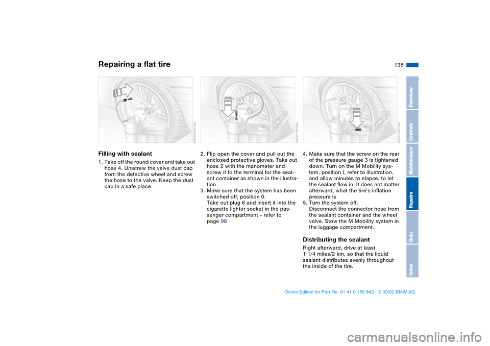
Filling with sealant1. Take off the round cover and take out
hose 4. Unscrew the valve dust cap
from the defective wheel and screw
the hose to the valve. Keep the dust
cap in a safe place
2. Flip open the cover and pull out the
enclosed protective gloves. Take out
hose 2 with the manometer and
screw it to the terminal for the seal-
ant container as shown in the illustra-
tion
3. Make sure that the system has been
switched off, position 0.
Take out plug 6 and insert it into the
cigarette lighter socket in the pas-
senger compartment – refer to
page 98
4. Make sure that the screw on the rear
of the pressure gauge 3 is tightened
down. Turn on the M Mobility sys-
tem, position I, refer to illustration,
and allow minutes to elapse, to let
the sealant flow in. It does not matter
afterward, what the tire's inflation
pressure is
5. Turn the system off.
Disconnect the connector hose from
the sealant container and the wheel
valve. Stow the M Mobility system in
the luggage compartment.Distributing the sealantRight afterward, drive at least
1 1/4 miles/2 km, so that the liquid
sealant distributes evenly throughout
the inside of the tire.
Repairing a flat tire
OverviewControlsMaintenanceRepairsDataIndex
handbook.book Page 135 Saturday, July 27, 2002 1:12 PM
Page 136 of 158

136
Do not exceed a maximum speed
of 40 mph / 60 km/h.
If possible, keep the vehicle speed
above 10 mph / 20 km/h. Stop in a suit-
able spot.<
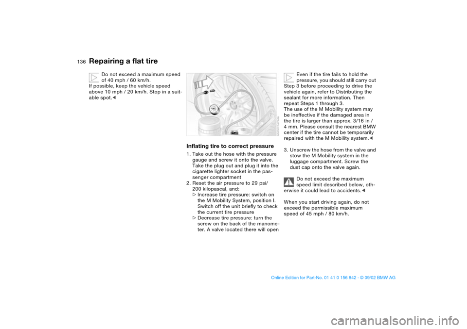
Inflating tire to correct pressure1. Take out the hose with the pressure
gauge and screw it onto the valve.
Take the plug out and plug it into the
cigarette lighter socket in the pas-
senger compartment
2. Reset the air pressure to 29 psi/
200 kilopascal, and:
>Increase tire pressure: switch on
the M Mobility System, position I.
Switch off the unit briefly to check
the current tire pressure
>Decrease tire pressure: turn the
screw on the back of the manome-
ter. A valve located there will open
Even if the tire fails to hold the
pressure, you should still carry out
Step 3 before proceeding to drive the
vehicle again, refer to Distributing the
sealant for more information. Then
repeat Steps 1 through 3.
The use of the M Mobility system may
be ineffective if the damaged area in
the tire is larger than approx. 3/16 in /
4 mm. Please consult the nearest BMW
center if the tire cannot be temporarily
repaired with the M Mobility system.<
3. Unscrew the hose from the valve and
stow the M Mobility system in the
luggage compartment. Screw the
dust cap onto the valve again.
Do not exceed the maximum
speed limit described below, oth-
erwise it could lead to accidents.<
When you start driving again, do not
exceed the permissible maximum
speed of 45 mph / 80 km/h.
Repairing a flat tire
handbook.book Page 136 Saturday, July 27, 2002 1:12 PM
Page 140 of 158

140
Towing the vehicleTowing eyeletThe towing eyelet, which can be
unscrewed, is in the luggage compart-
ment under the floor mat and must
remain in the vehicle. This eyelet is
designed for installation in the tow
sockets located at the front and rear of
the vehicle. It is intended for towing on
paved road surfaces only.
The towing eyelet should not be used
to pull a vehicle out of deep snow, mud,
sand, etc.
Comply with all applicable towing laws
and regulations at all times.
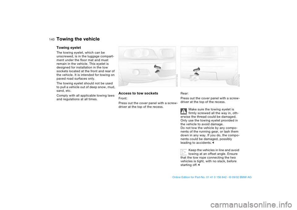
Access to tow socketsFront:
Press out the cover panel with a screw-
driver at the top of the recess.
Rear:
Press out the cover panel with a screw-
driver at the top of the recess.
Make sure the towing eyelet is
firmly screwed all the way in, oth-
erwise the thread could be damaged.
Only use the towing eyelet provided in
the vehicle to avoid damage.
Do not tow the vehicle by any compo-
nents of the running gear, or lash them
down in any way. If you do, the compo-
nents could be damaged, possibly
leading to accidents.<
Keep the vehicles in line and avoid
towing at an offset angle. Ensure
that the tow rope connecting the two
vehicles is tight, with no slack, before
starting off.<
handbook.book Page 140 Saturday, July 27, 2002 1:12 PM
Page 141 of 158

141
Use only a nylon towing strap to tow
the vehicle, since the inherent resil-
ience of this material helps protect both
vehicles from sudden jerking move-
ments.
The towed vehicle should always
be the lighter of the two vehicles.
If this is not the case, it will not be pos-
sible to control vehicle handling.
Never attempt to use your vehicle to
push another vehicle, since damage to
the energy-absorbing bumpers could
result.Towing a vehicle1. Gearshift lever in Neutral
2. Towing speed:
max. 45 mph / 70 km/h
3. Towing distance:
max. 95 miles/150 km
4. Leave the ignition key at position 1 to
ensure that the brake lamps, turn sig-
nal indicators, horn and windshield
wipers remain operative, and to pre-
vent the steering lock detent from
engaging
5. Switch on the hazard warning system
– observe applicable legal regula-
tions.
Find some means of identifying the
vehicle in tow, for instance, place a sign
or warning triangle in the rear window.
Make sure that the ignition key
remains in position 1 even when
the electrical system has failed to pre-
vent the steering lock from engaging.
The steering and brakes are without
power-assist when the engine is off.
This means that increased effort is
required for steering and braking.<
Vehicle with sequential M gearbox
SMG II:
To push or tow, engage selector lever
in position 0.
Never work on the vehicle with a
driving position engaged.<
Towing with a commercial tow
truck>Do not tow with sling-type equipment
>Use wheel lift or flatbed equipment
>Please comply with applicable state
towing laws.
Never allow passengers to ride in
a towed vehicle for any reason.
Never attach tie-down hooks, chains,
straps, or tow hooks to tie rods, control
arms, or any other part of the vehicle
suspension, as severe damage to these
components will occur, possibly lead-
ing to accidents.<
Towing the vehicle
OverviewControlsMaintenanceRepairsDataIndex
handbook.book Page 141 Saturday, July 27, 2002 1:12 PM
Page 152 of 158

Everything from A to ZEngine speed 144
Entering the rear 47
Exterior mirrors 51
Eyelet, towing 140
F
False alarm, avoiding 39
Fault displays 76
First-aid kit 23
Flat tire 109
repairing 133
Flat Tire Monitor 82
indicator lamp 18, 19
Fog lamps 88
Folding rear backrest 100
Follow me home lamps 86
Footbrake 108
see Driving notes 107
Footwell lamps 88
Front fog lamps 88
indicator lamp 20
Front seat adjustment 44
Frost protection,
radiator 120
Fuel 25
Fuel consumption 79
display 75
Fuel filler door 24
release following an elec-
trical malfunction 24
Fuel gauge 75
Fuel specifications 25Fuel tank capacity 147
Fuel tank display 75
Fuel tank gauge 75
Fuel-injection system 144
Fuses 138
replacing 138
G
Gasoline 25
gauge 75
Gearbox, sequential 65
Gearshift lever 64
Glove compartment 95
Gradient assistance 68
Grills 90
Gross vehicle weight 146
H
Hands-free system 97
Harman Kardon premium
sound system 95
Hazard warning flashers 14
Hazard warning triangle 23
Head airbags 53
Head restraints 46
Headlamp 86
Headlamp cleaning system
116, 118, 147
Headlamp control 86
Headlamp flasher 70, 87
Heated mirror 51
Heated seats 50Heavy loads 102
High beams 70, 87
indicator lamps 21
Holder for beverages 96
Hood release 114
Horn 14
Hydroplaning 107, 109
I
Ice warning 78
Ignition key 30
positions 60
Ignition lock 60
Imprint 4
Indicator lamps 18
Individual settings
Vehicle Memory, Key
Memory 59
Inflation pressure 25, 109
INSPECTION 76
Instrument cluster 16
Instrument lighting 87
Instrument panel 14, 16
Interface socket for onboard
diagnostics (OBD) 124
Interior lamps 32, 88
remote control 32
Interior motion sensor 38
remote control 32
switching off 32, 39Interior rearview mirror
automatic dimming
feature 52
Interior temperature
adjusting 92
Intermittent mode 71
J
Jump-starting 139
K
Key Memory 59
Keys 30
L
Lamps
daytime driving lamps 86
fog lamps 88
footwell lamps 88
headlamp flasher 70, 87
high beams 87
instrument lighting 87
interior lamps 88
low beams 86
parking lamps 86
reading lamps 88
replacing 129
standing lamps 87
Lashing fittings 103
LATCH child-restraint
mounting system 57
handbook.book Page 152 Saturday, July 27, 2002 1:12 PM
Page 155 of 158

Everything from A to Z
155
Tire tread 109
Tools 128
Torque 144
Towing eyelet 140
Towing the vehicle 140
Track 145
Transmission 64
Transporting children
safely 55
Tread depth, tires 109
Tread wear indicator 109
Trip odometer 74
Trunk, see Luggage com-
partment 35
capacity 146
Trunk lid, see Luggage com-
partment lid 35
Turn signal indicator 70
indicator lamps 20
replacing bulb 130
Turning circle 145
U
Uniform Tire Quality
Grading 111
Upholstery care, refer to the
Caring for your vehicle
brochure
Used batteries 137V
Vacuum cleaner, connect-
ing 98
Variable pre-warning
zone 74
Vehicle
break-in procedures 106
starting 61
switching off 63
Vehicle battery 137
Vehicle Memory 59
Vehicle weight 146
Ventilation 90
draft-free 93
Viscosity 119
Voice Control System, refer
to the separate Owner's
Manual
Voice recognition 22
W
Warning lamp "Please fasten
safety belts" 18
Warning lamps 18
Warning messages 76
Warranty and Service Guide
Booklet 122
Warranty, refer also to sepa-
rate booklet 6
Washer fluid
adding 118, 147
Washer/wiper system 71Washing fluid
indicator lamp 19
Washing vehicle, refer to the
Caring for your vehicle
brochure
Water on roadways
deep water 107
Wear indicator for tires 109
Weights 146
Wheelbase 145
Wheels and tires 112
Wheelslip control, see
DSC 81
Width 145
Window condensation,
removing 92
Windows
convenience operation
31, 33
defrosting 92
remote control 31
Windshield washer reservoir
filling 118, 147
Windshield wiper blades,
replacing 128
Windshield wipers 71
Winter tires 112
Wiper blades, replacing 128
Work in the engine compart-
ment 114X
Xenon lamps 129
OverviewControlsMaintenanceRepairsDataIndex
handbook.book Page 155 Saturday, July 27, 2002 1:12 PM