2003 AUDI A8 remote control
[x] Cancel search: remote controlPage 11 of 96
Downloaded from www.Manualslib.com manuals search engine 11
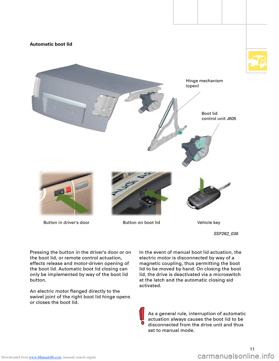
In the event of manual boot lid actuation, the
electric motor is disconnected by way of a
magnetic coupling, thus permitting the boot
lid to be moved by hand. On closing the boot
lid, the drive is deactivated via a microswitch
at the latch and the automatic closing aid
activated. Pressing the button in the driver's door or on
the boot lid, or remote control actuation,
effects release and motor-driven opening of
the boot lid. Automatic boot lid closing can
only be implemented by way of the boot lid
button.
An electric motor flanged directly to the
swivel joint of the right boot lid hinge opens
or closes the boot lid.
SSP282_036
Automatic boot lid
As a general rule, interruption of automatic
actuation always causes the boot lid to be
disconnected from the drive unit and thus
set to manual mode.
Hinge mechanism
(open)
Boot lid
control unit J605
Button in driver's door Button on boot lid Vehicle key
Page 62 of 96
Downloaded from www.Manualslib.com manuals search engine 62
Electrical System
BluetoothTM
BluetoothTM is an internationally standardised
remote control data interface.
It permits control or monitoring of even
minute units using radio waves.
The primary aim when developing this new
type of interface was to create a wireless
alternative to cable links, which used to be
susceptible to interference and inconvenient
and frequently featured incompatible
connectors.
More and more manufacturers are making use
of "Bluetooth
TM" radio wave technology for
example for wireless interconnection of
notebook and mobile phone accessories.
As initiator and main contributor to the
development of this new transmission
technology, the Swedish company Ericsson
chose the name "Bluetooth".
The name originates from the Viking king
Harald Blåtand II (Danish, literally meaning
"Blue Tooth"), who lived around 1000 years ago
in Denmark and Norway.
Motor vehicle applications
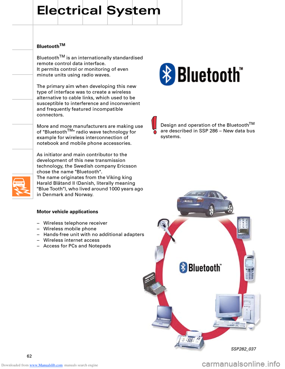
– Wireless telephone receiver
– Wireless mobile phone
– Hands-free unit with no additional adapters
– Wireless internet access
– Access for PCs and Notepads
SSP282_037
Design and operation of the BluetoothTM
are described in SSP 286 – New data bus
systems.
Page 64 of 96
Downloaded from www.Manualslib.com manuals search engine 64
Electrical System
Convenience and security
electronics
"Advanced Key" entry and start
authorisation system
"Advanced Key" can be taken to mean an
"advanced locking and security system".
It takes the form of a non-contacting key
recognition system. With the "Advanced Key"
package, the "Vehicle unlocking" and "Vehicle
locking" functions by way of a mechanical or
remote control key are supplemented by the non-
contacting functions "Vehicle unlocking" and
"Vehicle locking".
Functions
Advanced Key "unlocking"
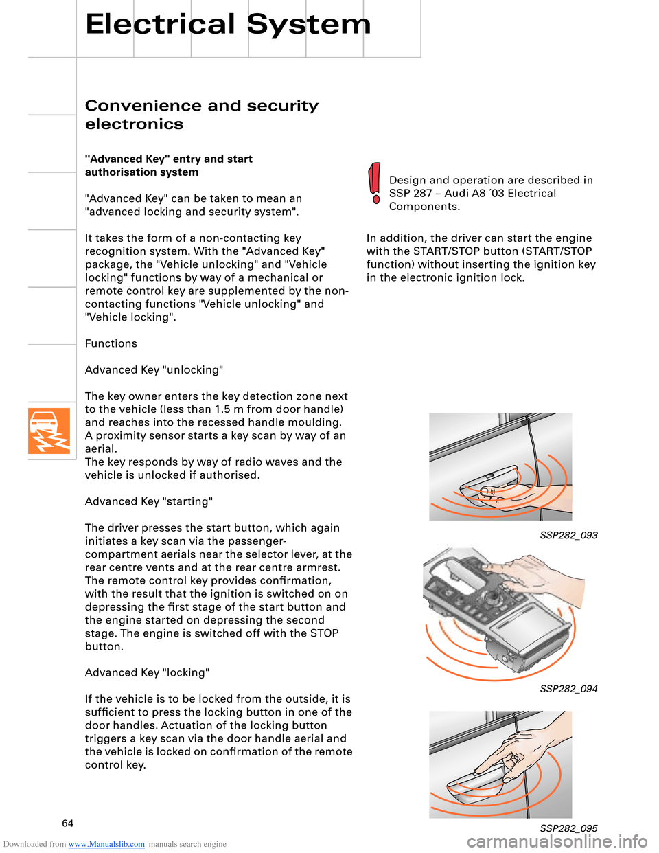
The key owner enters the key detection zone next
to the vehicle (less than 1.5 m from door handle)
and reaches into the recessed handle moulding.
aerial.
The key responds by way of radio waves and the
vehicle is unlocked if authorised.
Advanced Key "starting"
The driver presses the start button, which again
initiates a key scan via the passenger-
compartment aerials near the selector lever, at the
rear centre vents and at the rear centre armrest.
The remote control key provides confirmation,
with the result that the ignition is switched on on
depressing the first stage of the start button and
the engine started on depressing the second
stage. The engine is switched off with the STOP
button.
Advanced Key "locking"
If the vehicle is to be locked from the outside, it is
sufficient to press the locking button in one of the
door handles. Actuation of the locking button
triggers a key scan via the door handle aerial and
the vehicle is locked on confirmation of the remote
control key.In addition, the driver can start the engine
with the START/STOP button (START/STOP
function) without inserting the ignition key
in the electronic ignition lock.
SSP282_093
SSP282_094
SSP282_095
Design and operation are described in
SSP 287 – Audi A8 ´03 Electrical
Components.
A proximity sensor starts a key scan by way of an
Page 73 of 96
Downloaded from www.Manualslib.com manuals search engine 7374
A distinction is made between two air
conditioner unit versions
– 2-zone front and rear climate
control
– 4-zone front and rear climate
control
and three types of control and
display unit
– Air conditioner control panel with
no seat heating/ventilation
– Air conditioner control panel with
seat heating
– Air conditioner control panel with
seat heating and seat ventilation
(identified by part number index).
SSP282_099
Self-diagnosis
Fault diagnosis and measured value blocks
for air conditioner and seat heating system
can be read out by way of address words 08
"Air conditioner/heater electronics" and 28
"Rear climate control". The functions of and
exact procedure for self-diagnosis and
assisted fault-finding with VAS 5051 can be
found in the Heating/Air Conditioner
Workshop Manual for the relevant vehicle
model.
Operating principle
When the ignition is switched on, the
Climatronic control unit J255 starts up with
the same temperature, air distribution and
fresh-air blower speed settings etc. as were
applicable the last time the ignition was
switched off by way of the appropriate key or
using fingerprint recognition.
If fingerprint recognition has been
implemented, this has priority over key
recognition (refer also to SSP 287 – Audi A8 ´03
Electrical Components).
Personalised settings
The following settings can be made for each
climate control zone (front left, right and,
optionally, with 4-zone climate control rear left
and right):
– Left/right temperature
– Air flow
– Left/right air distribution
– Left/right seat heating
– Left/right seat ventilation
– Operating modes (AUTO for driver and front
passenger, temperature-adjustable centre
vents, automatically controlled
recirculated-air mode, ECON)
The heated windscreen can be activated by
way of the air conditioner defrost button or
the air conditioner control unit automatically
switches on the electric heated windscreen if
the appropriate conditions are satisfied
(windscreen defrost or automatic mode on
cold starting).
The Climatronic J255 and heated windscreen
J505 control units communicate by way of the
LIN bus. The Climatronic control unit transmits
the specified windscreen heating power to the
heated windscreen control unit on the LIN bus.
Heating/Air Conditioner
Key recognition takes place in the case of
remote control (radio or key transponder),
with the driver identification control unit
providing the Climatronic control unit J255
with the appropriate information by way of
the CAN bus.
The electrically heated windscreen is only
supplied with the amount of power which can
currently be drawn from the electrical system
without draining the battery. This is
monitored by the energy management
control unit J644.
As is the case with the Audi A4, the
windscreen is heated by applying voltage to a
metallic foil fitted in the glass (refer to
SSP 213).
As in the Audi A4, the air conditioner
compressor is regulated as a function of load
and controlled externally by way of the
compressor regulating valve (refer to
SSP 240). The Climatronic control unit J255 is
connected to the convenience CAN, via
which diagnosis is also performed.
A manual air conditioning system is not
available.
Page 75 of 96
Downloaded from www.Manualslib.com manuals search engine 75
3
36
Auto
21,5° C
63
3
The current air conditioner settings are stored
automatically and assigned to the
appropriate remote control key. On vehicles
with Audi one-touch memory (optional), the
current setting is also assigned to the
corresponding fingerprint. Air conditioning system control via MMI
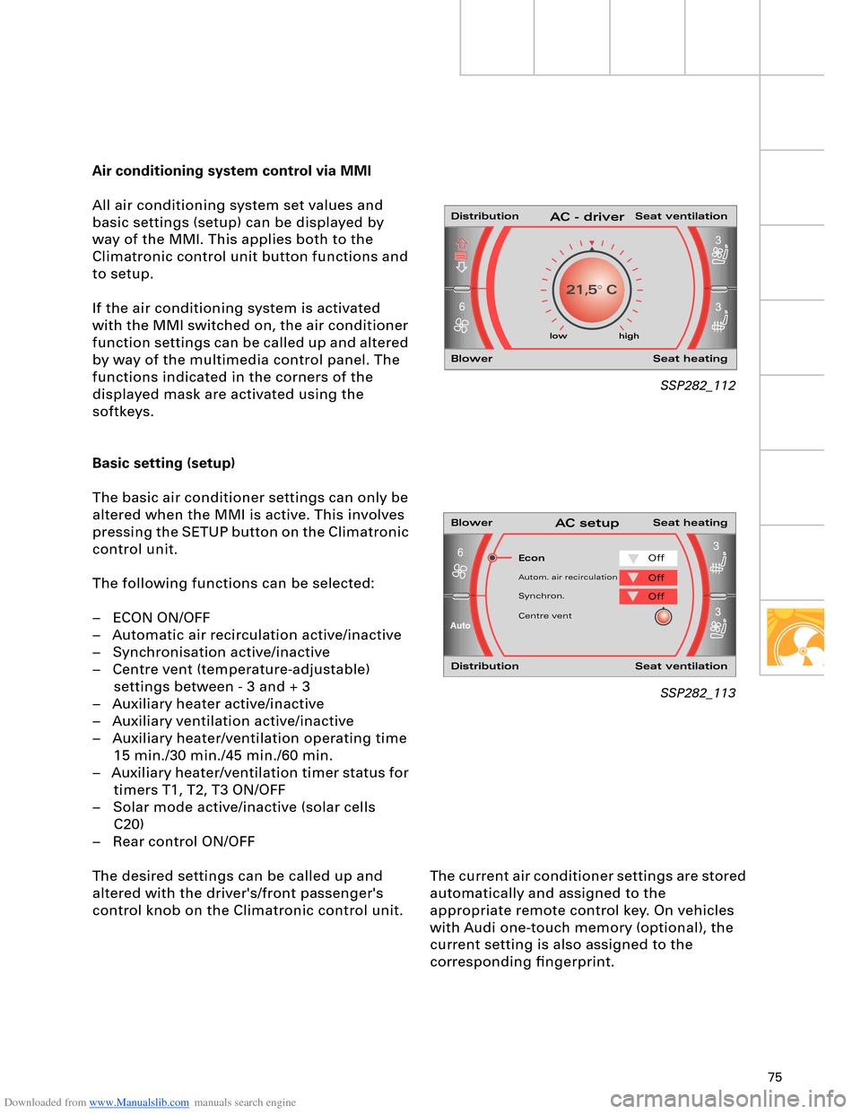
All air conditioning system set values and
basic settings (setup) can be displayed by
way of the MMI. This applies both to the
Climatronic control unit button functions and
to setup.
If the air conditioning system is activated
with the MMI switched on, the air conditioner
function settings can be called up and altered
by way of the multimedia control panel. The
functions indicated in the corners of the
displayed mask are activated using the
softkeys.
Basic setting (setup)
The basic air conditioner settings can only be
altered when the MMI is active. This involves
pressing the SETUP button on the Climatronic
control unit.
The following functions can be selected:
– ECON ON/OFF
– Automatic air recirculation active/inactive
– Synchronisation active/inactive
– Centre vent (temperature-adjustable)
settings between - 3 and + 3
– Auxiliary heater active/inactive
– Auxiliary ventilation active/inactive
– Auxiliary heater/ventilation operating time
15 min./30 min./45 min./60 min.
– Auxiliary heater/ventilation timer status for
timers T1, T2, T3 ON/OFF
– Solar mode active/inactive (solar cells
C20)
– Rear control ON/OFF
The desired settings can be called up and
altered with the driver's/front passenger's
control knob on the Climatronic control unit.
SSP282_112
SSP282_113
low high
Econ
Distribution Seat ventilation
Blower Seat heatingAC - driver
Blower Seat heatingAC setup
Distribution Seat ventilation
Off
Autom. air recirculationOff
Synchron.Off
Centre vent
Page 90 of 96
Downloaded from www.Manualslib.com manuals search engine 90
Auxiliary heater/coolant additional heater
An auxiliary heater is available as an option
for all vehicle and engine versions. The
auxiliary heater with petrol engines and
additional heater with diesel engines are
integrated into the engine coolant circuit.
Vehicles with diesel engine are fitted with an
additional heater as standard. On diesel
engines with auxiliary heater, the activated
auxiliary heater is also used as engine
additional heater depending on temperature.
Heating/Air Conditioner
Design and operation are described in
SSP 240 – Audi A2 Technical Features.
Operation with cut-in by way of remote
control or timer
In the Audi A8 ´03, the auxiliary heater is
activated by the air conditioner. The heated
coolant is initially supplied to the passenger
compartment (primarily auxiliary heater
mode). On attaining pre-determined
temperature levels, engine pre-heating is
then switched in in line with a characteristic
curve.
Activation sequence:
1 A remote control or timer signal is
transmitted to the auxiliary heater control
unit.
2 The auxiliary heater then transmits a signal
via the CAN bus to the Climatronic control
unit J255.
3 The control unit then decides as a function
of desired temperature, ambient
temperature and passenger compartment
temperature whether auxiliary ventilation
or auxiliary heating is to be employed.
The setting of the auxiliary heater/
ventilation function is shown in the setup
menu in the MMI (Multimedia-Interface).The cut-in time is "programmed" by way of
the MMI system (Multimedia Interface) under
the menu item "timer status".
4.1 Auxiliary ventilation sequence
The energy management control unit
J644 interrogates the battery capacity
check function of the battery and energy
management system to determine
whether auxiliary ventilation can be
accepted. In the event of acceptance, the
fresh-air blower is actuated.
Page 91 of 96
Downloaded from www.Manualslib.com manuals search engine 91
4.2 Auxiliary heating sequence
The level of fuel in the tank is
interrogated. If the fuel tank is "empty",
the auxiliary heating function is not
permitted and the auxiliary heater symbol
in the dash panel insert goes out. "Empty"
roughly corresponds to the red display
zone. The energy management control
unit J644 checks whether there is
sufficient energy to accept auxiliary
heating. If this is the case, the auxiliary
heater is switched on in the various
operating modes depending on the
characteristic temperature curve and the
fresh-air blower is actuated.
If the auxiliary heating temperature
reaches a level of 30 °C, the fresh-air
blower is activated and the coolant
shutoff valve N279 pulsed in line with the
characteristic curve.
The auxiliary heater is switched off
automatically on completion of the operating
time transmitted by the MMI system to the
Climatronic control unit or it can be switched
off using the remote control OFF button.
Auxiliary heater circulation pump control
To speed up heating of the passenger
compartment and to achieve a better "heat
yield" in the air conditioner unit heat
exchanger, the circulation pump V55 and
coolant shutoff valve N279 are pulsed as a
function of water temperature and the
heating circuit flow rate is thus reduced.
An electric circulation pump is used for the
auxiliary heater. It is not possible to reduce
the supply voltage in the auxiliary heater
control unit and the circulation pump is thus
actuated at specific intervals to decrease its
output.
Additional control curve for "auxiliary heater"
and "additional heater"
When the engine is on, the auxiliary heater
and engine temperatures are constantly
compared. A switch to the large coolant
circuit is made as soon as the engine
temperature exceeds the auxiliary heater
temperature.
Activation of auxiliary heater circulation
pump with engine on
(pulsed operation of circulation pump)
In order to be able to ensure a sufficient flow
of water through the heat exchanger, the
auxiliary heater circulation pump must
additionally be switched on, as is the case for
instance with the 12-cylinder engine.If the engine is switched off again and not
all additional heater criteria (temperature,
time) are satisfied, the auxiliary heater
remains in operation for any residual
operating time before being deactivated.
This function can be encoded.